
Related Manuals for Car-Interface v.LOGiC V5-CIC-F-PNP


Summary of Contents for Car-Interface v.LOGiC V5-CIC-F-PNP
- Page 1 v.LOGiC Intelligent Solution Interface V5-CIC-F-PNP Compatible with the F-series BMW with navigation system or radio and 7” or 10.2” monitor with 4pin HSD LVDS connector Version 26.11.2019 V5-CIC-F-PNP...
- Page 2 Product features • Own on-screen display and setup • Rear-view camera input • Automatic switching to rear-view camera input on engagement of reverse gear from all operation modes • Front camera input / SMART-LINK input • Control of SMART-LINK module over iDrive control panel •...
-
Page 3: Table Of Contents
Contents 1. Prior to Installation 1.1. Delivery contents 1.2. Check compatibility of vehicle and accessories 1.3. Setting the dip switches of the interface-box V5C-M636 1.4. LED’s of the interface-box V5C-M636 2. Connection schema 3. Installation 3.1. Connecting interface-box and harnesses 3.2. - Page 4 Legal Information By law, watching moving pictures while driving is prohibited, the driver must not be distracted. We do not accept any liability for material damage or personal injury resulting, directly or indirectly, from installation or operation of this product. This product should only be used while standing or to display fixed menus or rear-view-camera video when the vehicle is moving, for example the MP3 menu for DVD upgrades.
-
Page 5: Prior To Installation
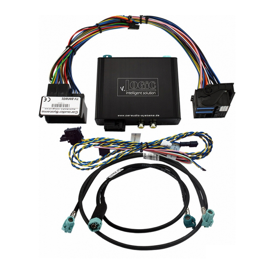
1. Prior to installation Read the manual prior to installation. Technical knowledge is necessary for installation. The place of installation must be free of moisture and away from heat sources. 1.1. Delivery contents Take down the SW-version and HW-version of the interface boxes, and store this manual for support purposes. -
Page 6: Setting The Dip Switches Of The Interface-Box V5C-M636
1.3. Setting the dip switches of the interface-box V5C-M636 Dip 1 and 2 on the back of the interface-box V5C-M636 are used to set the monitor type. The default setting is: Vehicle/ navigation Dip 1 Dip 2 Dip 3 CIC-F (F-series), 7“ monitor No function CIC-F (F-series), 10“... -
Page 7: Connection Schema
2. Connection schema Version 26.11.2019 V5-CIC-F-PNP... -
Page 8: Installation
3. Installation Switch off ignition and disconnect the vehicle’s battery! The interface needs a permanent 12V source. If according to factory rules disconnecting the battery is to be avoided, it is usually sufficient to put the vehicle is sleep-mode. In case the sleep-mode does not show success, disconnect the battery with a resistor lead. -
Page 9: Lvds Connection
Connect female 8 pin molex connector of the harness TV-BM01 to the male 8 pin molex connector of the harness TV-BM01. Connect female 12pin AMP connector of the harness TV-BM01 to the front site of the V5C-M636 interface box. 3.2. LVDS connection Connect the female 4pin HSD LVDS connector of the LVDS cable CAB-HSD-DD075-O to the male 4pin HSD LVDS connector (LVDS-IN) on the rear of the... -
Page 10: Connection To The Idrive
3.3. Connection to the iDrive Interface)box V5C)M636 FRONT V5C)UNI02; harness CAN$Low Female 10pin; CAN$High of iDrive CAN$Low,Pin,4 CAN$High,Pin,3 Remove the iDrive from the centre console and unplug the existing flat female 10pin or 4pin cable connector. Remove pin 3 green/orange CAN-high and pin 4 green CAN-low of vehicle harness from the female cable connector. -
Page 11: After-Market Front Camera
3.3.1. After-market front camera 3.3.1.1. Connection to the after-market front camera Interface)box V5C)M636 FRONT V5C)UNI028 harness Front8camera +12V8camera Power&Out&1&(max.&1A) power Connect the video RCA of the after-market front camera to the female RCA connector “FRONT CAM” of the interface box V5C-M636. The pink wire of harness V5C-UNI02 can be used for +12V electric power supply (max. -
Page 12: Settings For Connecting An After-Market Front Camera
3.3.1.2. Settings for connecting an after-market front camera You have to configure some settings in the OSD-menus INPUTS and MISC if you want to connect an after-market front camera (Operation of the OSD: see chapter “OSD-Operation”). OSD-menu Menu item Setting Explication No front camera connected FRONT CAM... -
Page 13: After-Market Rear-View Camera
3.3.2. After-market rear-view camera 3.3.2.1. Connection to the after-market rear-view camera Connect the video RCA of the after-market rear-view camera to the female RCA connector “REAR CAM” of the interface box V5C-M636. The green wire of harness TV-BM01 can be used for +12V electric power supply (max. -
Page 14: Settings For Connecting An After-Market Rear-View Camera
3.3.2.2. Settings for connecting an after-market rear-view camera You have to configure some settings in the OSD-menus INPUTS and MISC if you want to connect an after-market rear-view camera (Operation of the OSD: see chapter “OSD- Operation”). OSD-menu Menu item Setting Explication No rear-view camera connected... -
Page 15: Smart-Link
3.3.3. SMART-LINK The front camera input can alternatively be used for SMART-LINK set (CarPlay® & Android Auto® module) connection. In addition, the interface has the option of controlling the connected SMART-LINK module over the iDrive control panel. 3.3.3.1. SMART-LINK video and control connection Interface-box V5C-M636 FRONT... -
Page 16: Smart-Link Audio Connection
3.3.3.2. SMART-LINK audio connection By using an audio cable (sold separately), connect the audio output of the SMART- LINK module to the vehicle AUX input. 3.3.3.3. Settings for SMART-LINK connecting You have to configure some settings in the OSD-menu INPUTS if you want to connect the SMART-LINK module (Operation of the OSD: see chapter “OSD-Operation”). -
Page 17: Configurable Trigger Outputs
3.3.4. Configurable trigger outputs You can configure the both +12V trigger outputs separately. The pink wire is POWER OUT 1 and the green wire is POWER OUT 2. Note: You can configure the both trigger outputs in the OSD-menu MISC separately (Operation of the OSD: see chapter “OSD-Operation”). -
Page 18: Picture Settings
3.4. Picture settings You can change the picture settings in the OSD-menu IMAGE (activation by long pressing the OPTION -button). ◦ Brightness ◦ Contrast ◦ Saturation ◦ Hue ◦ Sharpness Note: The picture settings will be retained for each video input separately. 3.5. -
Page 19: Operation
4. Operation 4.1. OSD – On-screen display You can change the basic configurations of the interface in the OSD (on screen display). 4.1.1. OSD – Operation You can control the OSD by iDrive. 4.1.1.1. 8-button iDrive Version 26.11.2019 V5-CIC-F-PNP... -
Page 20: 2-Button Idrive In Mini
4.1.1.2. 2-button iDrive in Mini Long press = enter/ leave OSD Options Short press = leave OSD + back to the main menu Back + leaving Options Options 4.1.2. OSD – Additional setting options The following settings in the OSD-menus OSD and MISC can be configured over and above the described settings in this manual (Operation of the OSD: see chapter “OSD-Operation”): OSD-menu Menu item... -
Page 21: Video-In-Motion Function
4.2. Video-in-motion function It is possible to activate and deactivate the video-in-motion in the OSD menu “MISC” (Operation of the OSD: see chapter “OSD-Operation”). OSD-menu Menu item Setting Explication Video-in-motion activated MISC Video-in-motion deactivated For the V5-CIC-F-PNP the video-in-motion function is permanently active without disturbing the navigation performance. -
Page 22: Controlling Of The Connected Smart-Link Module
4.4. Controlling of the connected SMART-LINK module The picture shows which functions of the connected SMART-LINK module can be executed by iDrive control panel. Once the FVC/SmartPhone input is activated the iDrive control panel action will execute the function described in the picture. Version 26.11.2019 V5-CIC-F-PNP... -
Page 23: Specifications
5. Specifications Operation voltage 10.5 – 14.8V DC Stand-by power drain <0,1mA Operation power drain 190mA Power consumption 2,6W Temperature range -20°C to +80°C Weight (box only) 285g Measurements (box only) B x H x T 141 x 30 x 105 mm 6.
Need help?
Do you have a question about the v.LOGiC V5-CIC-F-PNP and is the answer not in the manual?
Questions and answers