Advertisement
Quick Links
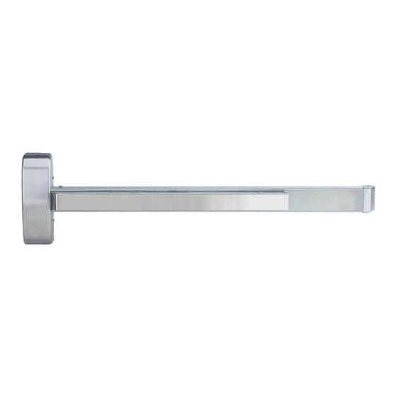
TOP Strike
Strike Screws
Latch Screws
TOP Latch
TOP Rod
U-Pin
Connector fix plate
Inner
Screws
Chassis
Screws
Bottom
Rod
Bottom Latch
Latch
Screws
Strike
Screws
Bottom
Strike
INSTALLATION INSTRUCTION
N-F98CVR CONCEALED VERTICAL ROD
EXIT DEVICE
Main Chassis
TO CHANGE BOTTOM LATCH FOR BOTTOM STRIKE
1.Device factory pre-set.
Mounting Rail
Push Rail
Main Chassis Screws
Head Cover
End Cap Screws
Mounting Plate
Bracket
Head Cover Screws
4. Change Done.
End Cap
Rail Mounting
Bracket Screw
Advertisement

Related Manuals for Cal-Royal N-F98CVR


Summary of Contents for Cal-Royal N-F98CVR
- Page 1 INSTALLATION INSTRUCTION N-F98CVR CONCEALED VERTICAL ROD EXIT DEVICE TOP Strike Strike Screws Latch Screws End Cap Screws TOP Latch End Cap Mounting Plate Bracket TOP Rod Rail Mounting Bracket Screw U-Pin Mounting Rail Connector fix plate Inner Screws Chassis Screws...
- Page 2 1.INSTALL INNER CHASSIS & TOP LATCH TOP Latch TOP Rod 5/32"-32 SCREWS (4pcs) Inner Chassis (TOP Latch must be under locked status during Step 3) (Insert Ø4.0mm Pin) under Inner Chassis while in depressed status (Keep the length of Top Rod Ass'y 3 to 5mm longer than upper door length) Adjust Top Rod Ass'y length Insert U-pin...
- Page 3 2.INSTALL BOTTOM LATCH (Skip this step if less Bottom Rod) Attached Rod to Bottom latch (Keep the length of Bottom Rod Ass'y 3 to 5mm PUSH longer than upper door length) (Bottom Latch must be under unlocked status during 2-2 installation) Adjust Top Rod Ass'y length Insert U-pin Install latch screws...
- Page 4 TO CHANGE HAND OF N-F98CVR EXIT DEVICE 1. LHR 2-1. Remove chassis pin & main slide & tube. 2-2. Remove lift lever & lift lever pin. 2-3. Rotate 180° main slide & lift lever main slide tube lift lever fixed screw...
Need help?
Do you have a question about the N-F98CVR and is the answer not in the manual?
Questions and answers