Advertisement
Quick Links
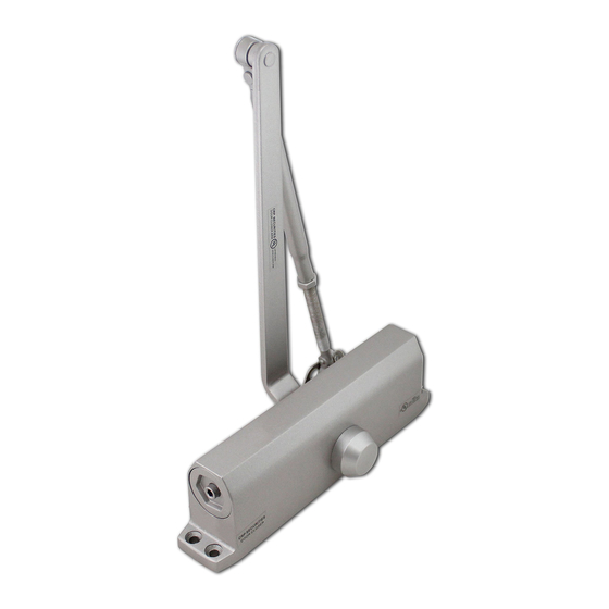
500 SERIES INSTALLATION GUIDELINE:
REGULAR ARM INSTALLATION (PULL SIDE) MOUNTING
6-1/2"(165mm)
3/4"
(19mm)
Hinge or Pivot
INSTALLATION GUIDELINES:
1. Select degree of opening from table and use template dimension shown in above. Mark 4 holes on the
door for door closer and two (2) holes on the frame for arm shoe.
2. Drill pilot holes in door and frame for #14 all-purpose screws or drill and tap for 1/4; 20 machine screws.
3. Install adjustable forearm/arm shoe assembly to frame using screw provided.
4. Install main arm to top pinion shaft using screw provided.
5. Mount closer on door using screws provided, SPRING POWER ADJUSTING NUT MUST BE POSITIONED AWAY
FROM HINGE EDGE.
6. Adjust length of adjustable forearm so that adjustable forearm is perpendicular to frame when assembled
to preloaded main arm ( Illustration ). Secure forearm to main arm with screw provided.
7. Snap pinion cap over shaft at bottom of closer, (When using full cover, pinion cap is not necessary).
8. Adjust closing speed, back check control and spring power of door, following instruction as shown.
9. Shown Illustration above in regards for 704 drop plate use to accommodate the door closer body mounting
in some cases.
1-9/16"(40mm)
1-1/4"(31.75mm)
BOTTOM OF FRAME
9-1/16"(230mm)
704
OPENING
DIM A
4-23/32"
TO 100°
(120 mm)
4-23/32"
100° - 120°
(120 mm)
OVER 180° 5-5/32" (80 mm)
•
RIGHT HAND DOOR SHOWN
•
LEFT HAND DOOR OPPOSITE
•
DIMENSIONS ARE IN INCHES
•
DRAWING NOT TO SCALE
Advertisement

Related Manuals for Cal-Royal 500 Series


Summary of Contents for Cal-Royal 500 Series
- Page 1 500 SERIES INSTALLATION GUIDELINE: REGULAR ARM INSTALLATION (PULL SIDE) MOUNTING 1-9/16”(40mm) 1-1/4”(31.75mm) 6-1/2”(165mm) OPENING DIM A BOTTOM OF FRAME 4-23/32” TO 100° (120 mm) 3/4” (19mm) 4-23/32” 100° - 120° (120 mm) OVER 180° 5-5/32” (80 mm) 9-1/16”(230mm) Hinge or Pivot •...
- Page 2 500 SERIES: TOP JAMB INSTALLATION (PUSH SIDE) 9-1/16”(230mm) 19/32”(15mm) 3/4” (19mm) BOTTOM OF FRAME 1-21/32”(42mm) OPENING DIM A 6-1/2” 1-9/16” 5-1/2” (165mm) (40mm) TO 100° (140 mm) 5-1/8” 100° - 120° (130 mm) Hinge or Pivot 3-17/32” OVER 180° (90 mm) •...
- Page 3 500 SERIES : PARALLEL ARM INSTALLATION (PUSH SIDE) 2-11/16”(68mm) 1-25/32”(45mm) 15/32”(11.5mm) 5/16”(8mm) OPENING DIM A DIM B 7-7/8” 5-29/32” TO 100° (200 mm) (150 mm) 6-11/16” 4-23/32” 120° - 180° 3/4”(19mm) 3”(76mm) (170 mm) (120 mm) • LEFT HAND DOOR SHOWN •...
- Page 4 500 SERIES ADJUSTMENT CLOSER ADJUSTMENT CLOSING CYCLE NOTE: Closing arcs ("CLOSE" and "LATCH") are controlled by two(2)separate speed adjusting valves, adjust the CLOS- ING speed first, then adjust the LATCHING speed. 1."CLOSING" speed adjustment is accomplished by full rotations of the speed adjusting valve.
Need help?
Do you have a question about the 500 Series and is the answer not in the manual?
Questions and answers