Advertisement
Quick Links
�
CAL-ROYAL
PRODUCTS, INC.
*
The screws (item C & D) , attach both machine & TEK
screws (for wood door installation). And Item 81 & 82 changed
to TEK screws (self-drilling screws) since 2014 , May.
L
'-l-- - --
I'
16
' '
���-
Dr��-
'
'
i'--,_
'
-
L
✓
'-_t,..--
-
---
.,,.
ll - - - -
r<..... __ .,,.
- -
CAL-ROYAL PRODUCTS, INC. USA I VERSION 2022
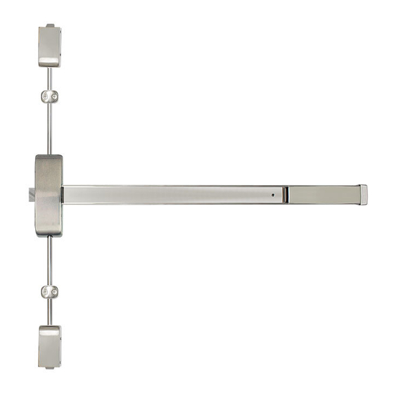
INSTALLATION INSTRUCTIONS
FOR 98-3PT SVR EXIT DEVICE
--0*2
B1*4
'
-�
�
........
',
,
B2*2
' , ,
- <
�
�
B1
Right - Hand Reverse Bevel
(RHR)
D
ITEM
1
[J
2
3
4
5
6
7
8
9
10
*4
11
*4
12
13
15
16
17
A
B1
B2
C
D
1
F
Determine handing of door
Left- Hand Reverse Bevel
(LHR)
Outside
C
ri,, <fi F
Lr
A*2
PARTS LIST
DESCRIPTION
PUSH RAIL
MOUNTING RAIL
HEAD COVER
CHASSIS ASSY
SLIDING COVER
BRACKET
END CAP
TOP LATCH
LATCH COVER
TOP ROD
TOP STRIKE
BOTTOM LATCH
BOTTOM ROD
ROD GUIDE
STRIKE
DOGGING HEX KEY
SM4X8 FLAT HEAD SCREWS
10# 1¼" TEK SCREWS (FLAT HEAD)
10# 1¼" TEK SCREWS (ROUND HEAD)
¾"
10#
SCREWS (FLAT HEAD)
%"
10#
SCREWS (ROUND HEAD)
10# 2" TEK SCREWS (FLAT HEAD)
Outside
(J
4
Push =;ide
7
Q'TY
MATERIAL
Noo-Rre Are
1
STEEUS304
1
STEEUS304
1
AUZINCISTEEUS304
1
STEEL
1
STEEUS304
1
STEEL
1
STEEUS304
1
STEEL
2
STEEUS304
1
AUS304
1
S304
1
STEEL
1
AUS304
2
STEEUS304
1
S304
1
STEEL
14
S304
6
STEEL
7
STEEL
1
STEEL
4
STEEL
4
STEEL
EDG-4045-01/23-1 of 8
Advertisement

Subscribe to Our Youtube Channel
Related Manuals for Cal-Royal 98-3PT


Summary of Contents for Cal-Royal 98-3PT
- Page 1 - - - - r<..__ .,,. 10# 1¼" TEK SCREWS (ROUND HEAD) STEEL ¾" SCREWS (FLAT HEAD) STEEL %" SCREWS (ROUND HEAD) STEEL 10# 2" TEK SCREWS (FLAT HEAD) STEEL EDG-4045-01/23-1 of 8 CAL-ROYAL PRODUCTS, INC. USA I VERSION 2022...
-
Page 2: Parts List
STEEL 10# 1¼" TEK SCREWS (ROUND HEAD) STEEL ..¾" SCREWS (FLAT HEAD) STEEL %" SCREWS (ROUND HEAD) STEEL � SEX BOLT STEEL 10# 2• TEK SCREWS (FLAT HEAD) STEEL EDG-4045-01/23-2 of 8 CAL-ROYAL PRODUCTS, INC. USA I VERSION 2022... - Page 3 (Non fire rated type shown) E ..- a> See Template ,/ ,,,, 8 ;--- � -=- � a> QI ..( � of Top Rod & Bottom Rod) -e-- -e- � "''----- FLOOR LINE EDG-4045-01/23-3 of 8 CAL-ROYAL PRODUCTS, INC. USA I VERSION 2022...
- Page 4 "FIRE RATED": "NON-"FIRE-RATED": STEP 2: INSTALL DEVICE & CUT DEVICE IF REQUIRED 2A. INSTALL DEVICE (1) Take off head cover and put device horizontally at the door. Fix screws (B1) on chassis but DO NOT tighten them at this step. (2) Install bracket with screw (B2).
- Page 5 ( 4) Put the Top Latch into the strike. Adjust the Proper gap between case and Top Latch. top latch case. top latch and strike which is about %/(2,0mm), Put Into EDG-4045-01/23-5 of 8 CAL-ROYAL PRODUCTS, INC. USA I VERSION 2022...
- Page 6 STEP 4: PREPARE BOTTOM LATCH & STEP 5: INSTALL BOTTOM STRIKE INSTALL BOTTOM LATCH Prepare Bottom Latch and Mark by TEMPLATE for Follow TEMPLATE to install bottom strike. Adjust the proper ½" later installation . gap between bottom latch and strike which is about Follow TEMP LA TE to install bottom latch with two (3.0mm), tighten screw (B2) firmly and then screw (B1).
- Page 7 (4). Passage : latch bolts are retracted by trim outside always open. ° Dogging:Use dogging hex key and turn clockwisely 90 when depressing push rail. Latch bolts will remain retracted. EDG-4045-01/23-7 of 8 CAL-ROYAL PRODUCTS, INC. USA I VERSION 2022...
- Page 8 STEP 10: CHANGE HANDING OF DEVICE TO CHANGE HANDING OF DEVICE -----, FOR EXAMPLE: FROM LHR to RHR LHR) "Y" Press Lift Arm "Y" and ensure the direction before changing. Unscrew "X" and take off "Z". RHR) ° Turn "Z" 180 and put it back as figure shown.
Need help?
Do you have a question about the 98-3PT and is the answer not in the manual?
Questions and answers