Advertisement
Quick Links
RHDSA-SS Arm Installation Instructions
�
CAL-ROYAL
for N900PBF Series Door Closers
PRODUCTS. INC .
Closer setup
A
Follow included template to properly prepare door frame
•
for all accessories of the closer installation.
A
Know the swing of the door which is being installed prior
•
to installation.
4
5
6
8
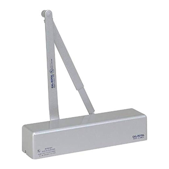
Surface closer system
The closer is comprised of the following components.
1.
Damper assembly
2.
Main arm
3.
Cover
4.
Pinion
5.
Delayed action adjustment
6.
Latch speech adjustment
7.
Closer body
Handing of the door
Tools recommended
• Drill Bits
Metal:
Wood: 5/32"
DPK: 1/8"
Sex nut:
-
Interior side of door
Left hand door (LH)
�
Exterior side of door
■ #3 Phillips screwdriver
7/32" & 1/4-20 tap
1 /2" or 13mm box wrench
■
• 1 0" adjustable wrench
3/8"
A
Verify closer spring size prior to installation. See "Spring
•
size chart" on page 2.
A
Make sure door efficiently operates prior to installing
•
closer.
,-- --- --- -- 10
_ _ _ _ _ _ _ _ _ g
8.
Closing/sweep speed adjustment
9.
Dust cap
10.
Backcheck action adjustment
11.
Connecting arm
.,,
Right hand door (RH)
�
i
)
3/16" hex key
■
• 5mm hex key (supplied)
DCG-1072-1 of 4-0624
Advertisement

Related Manuals for Cal-Royal N900PBF Series


Summary of Contents for Cal-Royal N900PBF Series
- Page 1 RHDSA-SS Arm Installation Instructions � CAL-ROYAL for N900PBF Series Door Closers PRODUCTS. INC . Closer setup Verify closer spring size prior to installation. See "Spring Follow included template to properly prepare door frame • • size chart" on page 2.
- Page 2 RHDSA-SS Arm Installation Instructions PULL SIDE, REGULAR MOUNT for N900PBF Series Door Closers Installation Instructions Mounting the surface closer & arm assembly (reg mnt) Right hand Non-hold open door shown Pinio n ----i -- � o ���c ting screw arm assembly , �...
- Page 3 RHDSA-SS Arm Installation Instructions PUSH SIDE, TOP JAMB MOUNT for N900PBF Series Door Closers Mounting the surface closer & arm assembly (top jamb mnt) Non-hold open Left hand door Left hand shown door shown Damper/ Damper _J,[r , '-.. assembly i' �...
- Page 4 RHDSA-SS Arm Installation Instructions CA L·R OYA L for N900PBF Series Door Closers PRODUCTS. INC . CLOSER ADJUSTMENTS Adjustments ,&. ,&. Confirm closer spring size prior to making any closing ° Maximum opening angle is 110 • speed adjustments. ,&.
Need help?
Do you have a question about the N900PBF Series and is the answer not in the manual?
Questions and answers