Table of Contents
Advertisement
Quick Links
Advertisement
Table of Contents

Related Manuals for Watson Marlow Pumps 621 Trio


Summary of Contents for Watson Marlow Pumps 621 Trio
- Page 1 621 Trio 621tr-gb-02.pdf...
-
Page 2: Two Year Warranty
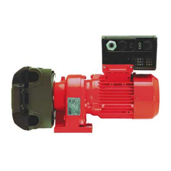
Declarations Declaration of When this pump unit is used as a stand alone pump it complies with: Machinery Directive conformity 98/37/EC EN60204-1, Low Voltage Directive 73/23/EEC EN61010-1, EMC Directive 89/336/EEC EN50081-1/EN50082-1. When this pump unit is to be installed into a machine or is to be assembled with other Declaration of machines for installations, it must not be put into service until the relevant machinery has been Incorporation... - Page 3 500 and 600 series close coupled pumps Details on the use, operation, maintenance and spare parts for the 500 and 600 series close coupled pumps can be found in the accompanying manual PB 0279. Trio cose coupled pump operating instructions Trio close coupled pumps combine a pumphead, motor/ gearbox and integral inverter into a robust IP55 pump.
-
Page 4: Control Cable Connections
Mains cable connections Ensure that the power source supplies the correct voltage and is designed for the rated current. Use a circuit-breaker with a 10A current rating between the power supply and Trio. Use Class 1 60/75°C copper wire only with a cross sectional area of 1mm. If crimp terminals are used they must be insulated. -
Page 5: Operating Information
Relay (24 V dc 1.0 A max) JP305 JP304 PI+ PI- P15+ DIN3 DIN2 DIN1 AIN- 0V P10+ AIN+ PI Power Digital Analogue Power for Supply (+15V Inputs Input Digital & max 50 mA) (7.5 - 33V, 0/2 - 10 V or Analogue Inputs max 5 mA) 0/4 - 20mA) - Page 6 2. Using the Watson-Marlow external potentiometer (when fitted): Apply mains power. Start the motor using the I/0 switch and adjust the potentiometer to obtain the desired speed. Reverse the direction of rotation using the switch. 3. Using the OPm2 hand held controller to select a set running speed Plug the OPm2 hand held controller into the Trio (see Fig.
-
Page 7: Fault Finding
4. Using external analogue control Remove the four M5 cross-head screws on the inverter’s cover to access the electrical terminals (see Fig.2). Connect a 4.7 kW potentiometer to the control terminals as shown in Fig. 3 or apply a 0 - 10 V signal between pin 2 (0V) and pin 3 (AIN+). -
Page 8: Fault Codes
Fault Codes In the event of a failure, the inverter switches off and a fault code can be viewed on the OPm2 display. The last fault that occurred is stored in parameter P930. e.g. ‘0003’ indicates that the last error was F003. Fault Code Cause Corrective Action F001... -
Page 9: Warning Codes
Warning Codes In the event of a warning, the inverter display will flash. The last warning to occur is stored in parameter P931. Warning Cause Corrective action Current limit active Check whether the motor power corresponds to the inverter power. Check that the cable length limits have not been exceeded. - Page 10 Parameter Function Default Your setting P053 Selection control function (DIN3 - terminal 7) fixed frequency 1 or binary fixed frequency bit 2 P071 Slip compensation (%) P072 Slip limit (%) P073 DC injection braking (%) P074 t motor derating P076 Pulse frequency P077 Control mode...
- Page 11 Product use and decontamination declaration In compliance with the UK Health & Safety at Work Act and the Control of Substances Hazardous to Health Regulations you, the user are required to declare the substances which have been in contact with the product(s) you are returning to Watson-Marlow or any of its subsidiaries or distributors.
Need help?
Do you have a question about the 621 Trio and is the answer not in the manual?
Questions and answers