Table of Contents
Advertisement
Quick Links
Advertisement
Table of Contents
Troubleshooting

Related Manuals for Supermicro A+ Server AS-1115S-FWTRT


Summary of Contents for Supermicro A+ Server AS-1115S-FWTRT
- Page 1 A+ Server ® AS -1115S-FWTRT AS -1115S-FDWTRT USER’S MANUAL Revision 1.0...
- Page 2 State of California, USA. The State of California, County of Santa Clara shall be the exclusive venue for the resolution of any such disputes. Supermicro's total liability for all claims will not exceed the price paid for the hardware product.
- Page 3 If you have any questions, please contact our support team at: support@supermicro.com This manual may be periodically updated without notice. Please check the Supermicro website for possible updates to the manual revision level. Secure Data Deletion A secure data deletion tool designed to fully erase all data from storage devices can be found on our website: https://www.supermicro.com/about/policies/disclaimer.cfm?url=/wdl/utility/...
-
Page 4: Table Of Contents
Preface Contents Chapter 1 Introduction 1.1 Overview ..........................8 1.2 System Features ........................9 Front View ...........................9 Rear View ..........................10 1.3 System Architecture ......................11 1.4 Motherboard Layout ......................12 Quick Reference Table ......................13 Motherboard Block Diagram .....................14 Chapter 2 Server Installation 2.1 Overview ..........................15 2.2 Unpacking the System .......................15 2.3 Preparing for Setup ......................15 Choosing a Setup Location ....................15... - Page 5 Preface Chapter 3 Maintenance and Component Installation 3.1 Removing Power .......................26 3.2 Accessing the System ......................27 3.3 Processor and Heatsink Installation ...................28 3.4 Memory Support and Installation ..................35 Memory Support ........................35 DIMM Module Population ....................36 DIMM Installation ......................37 DIMM Removal .........................37 3.5 Motherboard Battery ......................38 3.6 Storage Drives ........................39 Checking the Temperature of an NVMe Drive ..............41...
- Page 6 Preface Chapter 7 Troubleshooting and Support 7.1 Information Resources .......................64 Website ..........................64 Direct Links for the AS -1115S-FWTRT/FDWTRT System ..........64 Direct Links for General Support and Information ............64 7.2 BMC Interface ........................65 7.3 Troubleshooting Procedures .....................66 General Technique ......................66 No Power ..........................66 No Video ...........................67 System Boot Failure ......................67 Memory Errors ........................67...
- Page 7 San Jose, CA 95131 U.S.A. Tel: +1 (408) 503-8000 Fax: +1 (408) 503-8008 Email: marketing@supermicro.com (General Information) Sales-USA@supermicro.com (Sales Inquiries) Government_Sales-USA@supermicro.com (Gov. Sales Inquiries) support@supermicro.com (Technical Support) RMA@supermicro.com (RMA Support) Webmaster@supermicro.com (Webmaster) Website: www.supermicro.com Europe Address: Super Micro Computer B.V.
-
Page 8: Chapter 1 Introduction
Chapter 1: Introduction Chapter 1 Introduction 1.1 Overview This chapter provides a brief outline of the functions and features of the AS -1115S-FWTRT and the AS -1115S-FDWTRT. Both systems are based on the H13SVW-NT motherboard and the CSE-515B-R000WNP chassis. The following provides an overview of the specifications and capabilities of the AS -1115S-FWTRT/AS -1115S-FDWTRT. -
Page 9: System Features
Chapter 1: Introduction 1.2 System Features The following views of the system display the main features. Refer to Appendix C for additional specifications. Front View Power Button Dedicated IPMI Port VGA Port AC Power Supplies COM Port USB Ports RJ45 LAN Ports (PSU1, PSU2) Figure 1-1. -
Page 10: Rear View
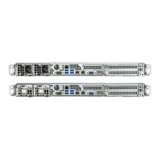
Chapter 1: Introduction Rear View Fans Service Tag Figure 1-3. Rear View System Features: Rear Feature Description Fans Six (internal) 4-cm counter-rotating fans Service Tag Service or asset tag has the BMC password details... -
Page 11: System Architecture
Chapter 1: Introduction 1.3 System Architecture This section shows the locations of the system's main components. Power Supplies DIMM Slots Processor System Fans Figure 1-4. Main Component Locations System Features: Top Feature Description Dual redundant modules Power Supplies AS -1115S-FWTRT: PWS-804S-1R AS -1115S-FDWTRT: PWS-601S-1R DIMM Slots Six DDR5 DIMM slots... -
Page 12: Motherboard Layout
Chapter 1: Introduction 1.4 Motherboard Layout Below is a layout of the H13SVW-NT motherboard with the jumper, connector and LED locations shown. See the table on the following page for descriptions. For detailed descriptions, pinout information and jumper settings, refer to Chapter 4 or the Motherboard Manual. -
Page 13: Quick Reference Table
USB 2/3 (3.0) Back panel USB 3.0 ports (USB 2/3) USB 4/5 (3.0) Internal USB 3.0 header (USB 4/5) JSXB1A, JSXB1B, Slots for Supermicro riser cards JSXB1C, JSXB2 JPI2C1 PWR supply (I2C) System Management Bus JPWR1 24-pin ATX power supply connector... -
Page 14: Motherboard Block Diagram
Chapter 1: Introduction Motherboard Block Diagram H13SVW-N/NT Rear I/O MLAN AMD SP6 Rev. 1.01 USB3.0 X 2 ID LED ID SW COM1 USB3.0 X 2 LAN1 LAN2 Rear 10Gb LAN 10Gb LAN IPMI LAN USB 3.0 SXB1 SXB2 RJ45 RJ45 RJ45 COM1 Rear... -
Page 15: Chapter 2 Server Installation
Chapter 2: Server Installation Chapter 2 Server Installation 2.1 Overview This chapter provides advice and instructions for mounting your system in a server rack. If your system is not already fully integrated with processors, system memory etc., refer to Chapter 3 for details on installing those specific components. -
Page 16: Rack Precautions
Chapter 2: Server Installation • This product is not suitable for use with visual display workplace devices according to §2 of the German Ordinance for Work with Visual Display Units. The ports of this equipment are suitable for connection to intra-building or unexposed wiring or cabling only. -
Page 17: Rack Mounting Considerations
Chapter 2: Server Installation • When not servicing, always keep the front door of the rack and all covers/panels on the servers closed to maintain proper cooling. • The AC power input ports are intended for installation in NEBS environments where rapid changes in line voltage may occur. - Page 18 Chapter 2: Server Installation To prevent bodily injury when mounting or servicing this unit in a rack, you must take special precautions to ensure that the system remains stable. The following guidelines are provided to ensure your safety: • This unit should be mounted at the bottom of the rack if it is the only unit in the rack. •...
-
Page 19: Installing The Rails
Chapter 2: Server Installation 2.4 Installing the Rails There are a variety of rack units on the market, which may require a slightly different assembly procedure. This rail set fits a rack between 25.6" and 33" deep. The following is a basic guideline for installing the system into a rack with the rack mounting hardware provided. -
Page 20: Installing The Outer Rails Onto The Rack
Chapter 2: Server Installation Installing the Outer Rails onto the Rack Each end of the assembled outer rail includes a bracket with square pegs to fit into your rack holes. If you have an older rack with round holes, these brackets must be removed, and you must use screws to secure the rail to the rack. -
Page 21: Installing The Server Into A Rack
Chapter 2: Server Installation 2.5 Installing the Server into a Rack Once rails are attached to the chassis and the rack, the chassis is ready to be installed into a rack. Installing the Chassis into a Rack 1. Confirm that inner and outer rails have been properly installed. 2. -
Page 22: Removing The Server From The Rack
Chapter 2: Server Installation Removing the Server from the Rack Caution! It is dangerous for a single person to off-load the heavy chassis from the rack without assistance. Be sure to have sufficient assistance supporting the chassis when removing it from the rack. -
Page 23: Installing The Server Into A Telco Rack
Chapter 2: Server Installation Installing the Server into a Telco Rack Follow the procedure below to install the chassis into a Telco (open type) rack. Installing the Chassis into a Telco Rack 1. Use the two L-shaped brackets (four total) to suspend the sides of the chassis within the rack. -
Page 24: Connecting Power And Ground In A Nebs Environment
Safety Ground, indicated by “Earth GND Symbol”. (Optional because Chassis GND stud is connected) • +Return, positive terminal (Battery Return, BR). Supermicro provides a cable for connection to the DC power supply. You should use the provided cable or an equivalent cable with the following specifications: • Positronic CBD connector. -
Page 25: Server Ground Stud Connections For Ac And Dc Systems
Chapter 2: Server Installation Note: The AS -1115S-FDWTRT is DC-I and can be grounded in both CBN and IBN networks. It is suitable for installation in Network Telecommunication Facilities and in locations where the NEC applies. Connection of the +Return (BR) supports both North America, Isolated GP (single point connection to CBN) and Europe, Integrated GP (Multiple point connection to CBN) configurations. -
Page 26: Chapter 3 Maintenance And Component Installation
Chapter 3: Maintenance and Component Installation Chapter 3 Maintenance and Component Installation This chapter provides instructions on installing and replacing main system components. To prevent compatibility issues, only use components that match the specifications and/or part numbers given. Installation or replacement of most components require that power first be removed from the system. -
Page 27: Accessing The System
Chapter 3: Maintenance and Component Installation 3.2 Accessing the System The AS -1115S-FWTRT/AS -1115S-FDWTRT features a removable top cover, which allows easy access to the inside of the chassis. Removing the Top Cover 1. Remove one screw and loosen the thumbscrew that holds the top cover in place. 2. -
Page 28: Processor And Heatsink Installation
CPU socket cap is in place and none of the socket pins are bent; otherwise, contact your retailer immediately. • Refer to the Supermicro website for updates on CPU support. Installing the Processor and Heatsink 1. Unscrew the screws holding down Force Frame in the sequence of 3-2-1. The screws are numbered on the force frame next to each screw hole. - Page 29 Chapter 3: Maintenance and Component Installation 2. The spring-loaded force frame will raise up after the last screw securing it (#1) is removed. Gently allow it to lift up to its stopping position. 3. Lift the rail frame up by gripping the lift tabs near the front end of the rail frame. While keeping a secure grip of the rail frame, lift it to a position so you can do the next step of removing the external cap.
- Page 30 Chapter 3: Maintenance and Component Installation 4. Remove the external cap from the Rail Frame by pulling it upwards through the rail guides on the rail frame. External Cap PnP Cover Cap 5. The CPU package is shipped from the factory with the blue carrier frame pre-assembled. Grip the handle of the carrier frame/CPU package assembly from its shipping tray, and while gripping the handle, align the flanges of the carrier frame onto the rails of the rail frame so its pins will be at the bottom when the rail frame is lowered later.
- Page 31 Chapter 3: Maintenance and Component Installation Note: You can only install the CPU inside the socket in one direction with the handle at the top. Make sure that it is properly inserted into the CPU socket before closing the rail frame plate.
- Page 32 Chapter 3: Maintenance and Component Installation 9. Gently lower the force frame down onto the rail frame and hold it in place until it is seated in the Socket housing. Note that the force frame is spring loaded and has to be held in place before it is secured.
- Page 33 Chapter 3: Maintenance and Component Installation 11. After the force frame is secured and the CPU package is in place, now you must install the heatsink to the frame. Lower the heatsink down till it rests securely over the four screw holes on CPU package on the socket frame.
- Page 34 Chapter 3: Maintenance and Component Installation Uninstalling the Processor and Heatsink 1. Remove the heatsink attached to the top of the CPU package by reversing the installation procedure. 2. Clean the Thermal grease left by the heatsink on the CPU package lid to limit the risk of it contaminating the CPU package land pads or contacts in the socket housing.
-
Page 35: Memory Support And Installation
Chapter 3: Maintenance and Component Installation 3.4 Memory Support and Installation Note: Check the Supermicro website for recommended memory modules. Important: Exercise extreme care when installing or removing DIMM modules to prevent any possible damage. Memory Support The H13SVW-NT supports up to 576 GB of ECC DDR5 4800 MT/s speed, RDIMM memory in six slots. -
Page 36: Dimm Module Population
Chapter 3: Maintenance and Component Installation DIMM Module Population When populating the motherboard with DIMM modules, please keep in mind the following: • Always use DDR5 DIMM modules of the same type, size and speed. • All six memory channels should be populated with each channel having equal capacity, which should provide the best performance in most cases. -
Page 37: Dimm Installation
Chapter 3: Maintenance and Component Installation DIMM Installation 1. Insert the desired number of DIMMs into the memory slots, starting from DIMMA1 Refer to the DIMM Module Population section. 2. Push the release tabs outwards on both Receptive Point ends of the DIMM slot to unlock it. 3. -
Page 38: Motherboard Battery
Chapter 3: Maintenance and Component Installation 3.5 Motherboard Battery The motherboard uses non-volatile memory to retain system information when system power is removed. This memory is powered by a lithium battery residing on the motherboard. Replacing the Battery Begin by removing power from the system. -
Page 39: Storage Drives
These carriers also help promote proper airflow. Note: Enterprise level drives are recommended for use in Supermicro chassis and servers. For information on recommended drives, visit the Supermicro website product pages at www. - Page 40 Chapter 3: Maintenance and Component Installation 4. Secure the drive bracket to the chassis floor using four screws, as shown below. 5. Connect the drive cables to the motherboard and the power supply. 6. If necessary, reinstall the PCI expansion card. 7.
-
Page 41: Checking The Temperature Of An Nvme Drive
Chapter 3: Maintenance and Component Installation Checking the Temperature of an NVMe Drive There are two ways to check using the BMC Dashboard. Checking a Drive • BMC Dashboard > Server Health > NVMe SSD – Shows the temperatures of all NVMe drives. -
Page 42: System Cooling
Chapter 3: Maintenance and Component Installation 3.7 System Cooling The AS -1115S-FWTRT/AS -1115S-FDWTRT comes standard with six counter-rotating fans. Two additional fans may be added as an option. The fans can adjust their speed according to the heat level sensed in the system, which results in more efficient and quieter operation. -
Page 43: Air Shrouds
Chapter 3: Maintenance and Component Installation Air Shrouds The AS -1115S-FWTRT/AS -1115S-FDWTRT supports two air shrouds, one to direct airflow to the CPU and another to direct airflow to the PCIe cards. There are two types of PCIe card air shrouds, one for full-height cards and one for half-height cards. Replacing the Air Shroud 1. -
Page 44: Checking The Server Air Flow
Chapter 3: Maintenance and Component Installation Checking the Server Air Flow • Make sure there are no objects to obstruct airflow in and out of the server. • Use only recommended server parts. • Make sure no wires or foreign objects obstruct air flow through the chassis. Pull all excess cabling out of the airflow path or use shorter cables. -
Page 45: Power Supply
100 V to 240 V input range. The 600 W DC power supplies can operate at a -44 Vdc to -65 Vdc input range. If replacing a power supply, the system does not need to be powered down. New units can be ordered directly from Supermicro or authorized distributors Replacing an AC Power Supply 1. - Page 46 Chapter 3: Maintenance and Component Installation Replacing a DC Power Supply 1. Use the system's remote management utility to find the failed power supply. 2. Check the power supply's LED. Power Supply LED States LED Color Definition No power input Amber Power supply is off or failed Power supply is on and...
-
Page 47: Chapter 4 Motherboard Connections
Chapter 4: Motherboard Connections Chapter 4 Motherboard Connections This section describes the connections on the motherboard and provides pinout definitions. Note that depending on how the system is configured, not all connections are required. The LEDs on the motherboard are also described here. A motherboard layout indicating component locations may be found in Chapter 1. - Page 48 Chapter 4: Motherboard Connections Power Fail LED The Power Fail LED connection is located on pins 5 and 6 of JF1. Refer to the table below for pin definitions. Power Fail LED Pin Definitions (JF1) Pin# Definition Ground UID LED The UID LED is on pins 7 and 8 of JF1.
- Page 49 Chapter 4: Motherboard Connections Power LED The Power LED connection is located on pins 15 and 16 of JF1. Refer to the table below for pin definitions. Power LED Pin Definitions (JF1) Pin# Definition +5 V Ground NMI Switch The non-maskable interrupt button header is located on pins 19 and 20 of JF1. Refer to the table below for pin definitions.
-
Page 50: Headers And Connectors
Chapter 4: Motherboard Connections 4.2 Headers and Connectors Power SMB Header (JPI2C1) The Power System Management Bus (I2C) header monitors power supply, fan, and system temperatures. See the table below for pin definitions. Power SMB Header Pin Definitions Pin# Definition Clock Data PWR Fail... - Page 51 Port 80 connection. Use this header to enhance system performance and data security. Refer to the table below for pin definitions. Please go to the following link for more information on the TPM: http://www.supermicro.com/manuals/other/TPM.pdf. Trusted Platform Module Header Pin Definitions...
- Page 52 Chapter 4: Motherboard Connections Chassis Intrusion (JL1) A Chassis Intrusion header is located at JL1 on the motherboard. Attach the appropriate cable from the chassis to the header to inform you when the chassis is opened. Chassis Intrusion Pin Definitions Pins Definition Ground...
- Page 53 Chapter 4: Motherboard Connections IPMB System Management Bus Header (JIPMB1) A System Management Bus header for IPMI 2.0 is located at JIPMB1. Connect the appropriate cable here to use the IPMB I C connection on your system. IPMB Header Pin Definitions Pin# Definition Data...
-
Page 54: Input/Output Ports
Chapter 4: Motherboard Connections 4.3 Input/Output Ports See the figure below for the locations and descriptions of the I/O ports on the rear of the motherboard. Figure 4-1. I/O Port Locations and Definitions Rear I/O Ports Description Description Description COM Port USB 2 (3.0) VGA Port BMC LAN Port... - Page 55 LED indicators. The UID Indicator provides easy identification of a system that may be in need of service. Note: UID can also be triggered via IPMI on the motherboard. For more information on IPMI, please refer to the IPMI User's Guide posted on our website at http://www.supermicro.com...
-
Page 56: Front Control Panel
JF1 contains header pins for various buttons and indicators that are normally located on a control panel at the front of the chassis. These connectors are designed specifically for use with Supermicro chassis. See the figure below for the location of JF1. Figure 4-2. JF1 Pin Definitions... -
Page 57: Jumpers
Chapter 4: Motherboard Connections 4.5 Jumpers Explanation of Jumpers To modify the operation of the motherboard, jumpers can be used to choose between optional settings. Jumpers create shorts between two pins to change the function of the connector. Pin 1 is identified with a thicker border line on the printed circuit board. See the diagram below for an example of jumping pins 1 and 2. -
Page 58: Led Indicators
Chapter 4: Motherboard Connections 4.6 LED Indicators Onboard LAN Port LEDs The motherboard's Ethernet ports have two LED indicators. The Activity LED is green and indicates connection and activity. The Link LED may be green, orange/amber, or off to indicate the speed of the connection. Refer to the tables below for more information. Link LED, Connection Link, Speed Indicator LED Color... - Page 59 Chapter 4: Motherboard Connections UID LED Indicator (LED9) The rear LED9 is located next to the UID switch. The front UID LED is located on the front panel. When you press the UID switch, both rear LED9 and front UID LED indicators will turn on.
-
Page 60: Chapter 5 Software
The Supermicro website contains drivers and utilities for your system at https://www. supermicro.com/wdl/driver. Some of these must be installed, such as the chipset driver. After accessing the website, go into the CDR_Images (in the parent directory of the above link) and locate the ISO file for your motherboard. Download this file to a USB flash or media drive. -
Page 61: Superdoctor ® 5
5.2 SuperDoctor ® The Supermicro SuperDoctor 5 is a program that functions in a command-line or web-based interface for Windows and Linux operating systems. The program monitors such system health information as CPU temperature, system voltages, system power consumption, fan speed, and provides alerts via email or Simple Network Management Protocol (SNMP). -
Page 62: Bmc
There are several BIOS settings that are related to BMC. For general documentation and information on BMC, visit our website at: https://www.supermicro.com/en/solutions/management-software/bmc-resources BMC ADMIN User Password For security, each system is assigned a unique default BMC password for the ADMIN user. -
Page 63: Chapter 6 Optional Components
Chapter 6: Optional Components Chapter 6 Optional Components This chapter describes optional system components and installation procedures. 6.1 Optional Parts List Optional Parts List Description Part Number CBL-PWEX-1361-10 GPU power cable CBL-PWEX-1240 SATA cable CBL-SAST-1251-100 Air shroud MCP-310-51512-0B... -
Page 64: Chapter 7 Troubleshooting And Support
Chapter 7 Troubleshooting and Support 7.1 Information Resources Website A great deal of information is available on the Supermicro website, supermicro.com. Figure 7-1. Supermicro Website • Specifications for servers and other hardware are available by clicking the menu icon, then selecting the Products option. -
Page 65: Bmc Interface
Security Center for recent security notices Supermicro Phone and Addresses 7.2 BMC Interface The system supports a Baseboard Management Controller (BMC) interface. It provides remote access, monitoring and management. There are several BIOS settings related to the BMC. -
Page 66: Troubleshooting Procedures
Chapter 6: Troubleshooting and Support 7.3 Troubleshooting Procedures Use the following procedures to troubleshoot your system. If you have followed all of the procedures below and still need assistance, refer to the Technical Support Procedures Returning Merchandise for Service section(s) in this chapter. Power down the system before changing any non hot-swap hardware components. -
Page 67: No Video
• Memory: Make sure that the memory modules are supported. Refer to the product page on our website at www.supermicro.com. Test the modules using memtest86 or a similar utility. • Storage drives: Make sure that all drives work properly. Replace if necessary. - Page 68 Also check the Control panel Overheat LED. • Adequate power supply: Make sure that the power supply provides adequate power to the system. Make sure that all power connectors are connected. Refer to the Supermicro website for the minimum power requirements. •...
-
Page 69: Crash Dump Using The Bmc Dashboard
In the event of a processor internal error (IERR) that crashes your system, you may want to provide information to support staff. You can download a crash dump of status information using the BMC Dashboard. The BMC manual is available at https://www.supermicro.com/ manuals/other/BMC_IPMI_X13_H13.pdf. Check Error Log 1. -
Page 70: Cmos Clear
Chapter 6: Troubleshooting and Support 7.5 CMOS Clear JBT1 is used to clear CMOS, which will also clear any passwords. Instead of pins, this jumper consists of contact pads to prevent accidentally clearing the contents of CMOS. To Clear CMOS 1. -
Page 71: Where To Get Replacement Components
7.6 Where to Get Replacement Components If you need replacement parts for your system, to ensure the highest level of professional service and technical support, purchase exclusively from our Supermicro Authorized Distributors/System Integrators/Resellers. A list can be found at: http://www.supermicro.com. -
Page 72: Vendor Support Filing System
For issues related to Red Hat Enterprise Linux, since it is a subscription based OS, contact your account representative. 7.8 Feedback Supermicro values your feedback as we strive to improve our customer experience in all facets of our business. To provide feedback on our manuals, please email us at techwriterteam@... -
Page 73: Appendix A Standardized Warning Statements For Ac Systems
Supermicro's Technical Support department for assistance. Only certified technicians should attempt to install or configure components. Read this appendix in its entirety before installing or configuring components in the Supermicro chassis. These warnings may also be found on our website at http://www.supermicro.com/about/... - Page 74 Appendix A: Warning Statements Warnung WICHTIGE SICHERHEITSHINWEISE Dieses Warnsymbol bedeutet Gefahr. Sie befinden sich in einer Situation, die zu Verletzungen führen kann. Machen Sie sich vor der Arbeit mit Geräten mit den Gefahren elektrischer Schaltungen und den üblichen Verfahren zur Vorbeugung vor Unfällen vertraut. Suchen Sie mit der am Ende jeder Warnung angegebenen Anweisungsnummer nach der jeweiligen Übersetzung in den übersetzten Sicherheitshinweisen, die zusammen mit diesem Gerät ausgeliefert wurden.
- Page 75 Appendix A: Warning Statements . ٌ ا ك ً ف حالة و ٌ يك أى تتسبب ف اصابة جسذ ة ٌ هذا الزهز ع ٌ خطز !تحذ ز قبل أى تعول عىل أي هعذات،يك عىل علن بالوخاطز ال ا ٌجوة عي الذوائز ٍ...
- Page 76 Appendix A: Warning Statements Warnung Vor dem Anschließen des Systems an die Stromquelle die Installationsanweisungen lesen. ¡Advertencia! Lea las instrucciones de instalación antes de conectar el sistema a la red de alimentación. Attention Avant de brancher le système sur la source d'alimentation, consulter les directives d'installation. .יש...
- Page 77 Appendix A: Warning Statements Warnung Dieses Produkt ist darauf angewiesen, dass im Gebäude ein Kurzschluss- bzw. Überstromschutz installiert ist. Stellen Sie sicher, dass der Nennwert der Schutzvorrichtung nicht mehr als: 250 V, 20 A beträgt. ¡Advertencia! Este equipo utiliza el sistema de protección contra cortocircuitos (o sobrecorrientes) del edificio.
- Page 78 Appendix A: Warning Statements Power Disconnection Warning Warning! The system must be disconnected from all sources of power and the power cord removed from the power supply module(s) before accessing the chassis interior to install or remove system components (except for hot-swap components). 電源切断の警告...
- Page 79 Appendix A: Warning Statements אזהרה מפני ניתוק חשמלי !אזהרה יש לנתק את המערכת מכל מקורות החשמל ויש להסיר את כבל החשמלי מהספק .לפני גישה לחלק הפנימי של המארז לצורך התקנת או הסרת רכיבים يجب فصم اننظاو من جميع مصادر انطاقت وإ ز انت سهك انكهرباء من وحدة امداد انطاقت...
- Page 80 Appendix A: Warning Statements Attention Seul le personnel autorisé et le personnel de maintenance qualifié doivent être autorisés à installer, remplacer ou entretenir cet équipement.. !אזהרה .יש לאפשר רק צוות מורשה ואנשי שירות מוסמכים להתקין, להחליף או לטפל בציוד זה .ينبغي...
- Page 81 Appendix A: Warning Statements Warnung Diese Einheit ist zur Installation in Bereichen mit beschränktem Zutritt vorgesehen. Der Zutritt zu derartigen Bereichen ist nur mit einem Spezialwerkzeug, Schloss und Schlüssel oder einer sonstigen Sicherheitsvorkehrung möglich. ¡Advertencia! Esta unidad ha sido diseñada para instalación en áreas de acceso restringido. Sólo puede obtenerse acceso a una de estas áreas mediante la utilización de una herramienta especial, cerradura con llave u otro medio de seguridad.
- Page 82 Appendix A: Warning Statements Battery Handling Warning! There is the danger of explosion if the battery is replaced incorrectly. Replace the battery only with the same or equivalent type recommended by the manufacturer. Dispose of used batteries according to the manufacturer's instructions 電池の取り扱い...
- Page 83 Appendix A: Warning Statements هناك خطر من انفجار يف حالة اسحبذال البطارية بطريقة غري صحيحة فعليل اسحبذال البطارية فقط بنفس النىع أو ما يعادلها مام أوصث به الرشمة املصنعة جخلص من البطاريات املسحعملة وفقا لحعليامت الرشمة الصانعة 경고! 배터리가 올바르게 교체되지 않으면 폭발의 위험이 있습니다. 기존 배터리와 동일하거나 제 조사에서...
- Page 84 Appendix A: Warning Statements ¡Advertencia! Puede que esta unidad tenga más de una conexión para fuentes de alimentación. Para cortar por completo el suministro de energía, deben desconectarse todas las conexiones. Attention Cette unité peut avoir plus d'une connexion d'alimentation. Pour supprimer toute tension et tout courant électrique de l'unité, toutes les connexions d'alimentation doivent être débranchées.
- Page 85 Appendix A: Warning Statements Backplane Voltage Warning! Hazardous voltage or energy is present on the backplane when the system is operating. Use caution when servicing. バックプレーンの電圧 システムの稼働中は危険な電圧または電力が、 バックプレーン上にかかっています。 修理する際には注意く ださい。 警告 当系统正在进行时,背板上有很危险的电压或能量,进行维修时务必小心。 警告 當系統正在進行時,背板上有危險的電壓或能量,進行維修時務必小心。 Warnung Wenn das System in Betrieb ist, treten auf der Rückwandplatine gefährliche Spannungen oder Energien auf.
- Page 86 Appendix A: Warning Statements هناك خطز مه التيار الكهزبايئ أوالطاقة املىجىدة عىل اللىحة عندما يكىن النظام يعمل كه حذ ر ا عند خدمة هذا الجهاس 경고! 시스템이 동작 중일 때 후면판 (Backplane)에는 위험한 전압이나 에너지가 발생 합니다. 서비스 작업 시 주의하십시오. Waarschuwing Een gevaarlijke spanning of energie is aanwezig op de backplane wanneer het systeem in gebruik is.
- Page 87 Appendix A: Warning Statements תיאום חוקי החשמל הארצי !אזהרה .התקנת הציוד חייבת להיות תואמת לחוקי החשמל המקומיים והארציים تركيب املعدات الكهربائية يجب أن ميتثل للقىاويه املحلية والىطىية املتعلقة بالكهرباء 경고! 현 지역 및 국가의 전기 규정에 따라 장비를 설치해야 합니다. Waarschuwing Bij installatie van de apparatuur moet worden voldaan aan de lokale en nationale elektriciteitsvoorschriften.
- Page 88 Appendix A: Warning Statements Attention La mise au rebut ou le recyclage de ce produit sont généralement soumis à des lois et/ou directives de respect de l'environnement. Renseignez-vous auprès de l'organisme compétent. סילוק המוצר !אזהרה .סילוק סופי של מוצר זה חייב להיות בהתאם להנחיות וחוקי המדינה التخلص...
- Page 89 Appendix A: Warning Statements Warnung Gefährlich Bewegende Teile. Von den bewegenden Lüfterblätter fern halten. Die Lüfter drehen sich u. U. noch, wenn die Lüfterbaugruppe aus dem Chassis genommen wird. Halten Sie Finger, Schraubendreher und andere Gegenstände von den Öffnungen des Lüftergehäuses entfernt.
- Page 90 Verbindungskabeln, Stromkabeln und/oder Adapater, die Ihre örtlichen Sicherheitsstandards einhalten. Der Gebrauch von anderen Kabeln und Adapter können Fehlfunktionen oder Feuer verursachen. Die Richtlinien untersagen das Nutzen von UL oder CAS zertifizierten Kabeln (mit UL/CSA gekennzeichnet), an Geräten oder Produkten die nicht mit Supermicro gekennzeichnet sind.
- Page 91 .قيرح وأ لطع يف ببستي دق ىرخأ تالوحمو تالباك يأ مادختسا .ميلسلا سباقلاو لصوملا مجح لبق نم ةدمتعملا تالباكلا مادختسا تادعملاو ةيئابرهكلا ةزهجألل ةمالسلا نوناق رظحيUL وأCSA ( ةمالع لمحت يتلاوUL/CSA) لبق نم ةددحملاو ةينعملا تاجتنملا ريغ ىرخأ تادعم يأ عمSupermicro.
- Page 92 사항을 준수하여 제공되거나 지정된 연결 혹은 구매 케이블, 전원 케이블 및 AC 어댑터를 사용하십시오. 다른 케이블이나 어댑터를 사용하면 오작동이나 화재가 발생할 수 있습니다. 전기 용품 안전법은 UL 또는 CSA 인증 케이블 (코드에 UL / CSA가 표시된 케이블)을 Supermicro 가 지정한 제품 이외의 전기 장치에 사용하는 것을 금지합니다. Stroomkabel en AC-Adapter...
-
Page 93: Appendix B Standardized Warning Statements For Dc Systems
Supermicro's Technical Support department for assistance. Only certified technicians should attempt to install or configure components. Read this appendix in its entirety before installing or configuring components in the Supermicro chassis. These warnings may also be found on our website at http://www.supermicro.com/about/... - Page 94 Appendix B: Standardized Warning Statements Warnung WICHTIGE SICHERHEITSHINWEISE Dieses Warnsymbol bedeutet Gefahr. Sie befinden sich in einer Situation, die zu Verletzungen führen kann. Machen Sie sich vor der Arbeit mit Geräten mit den Gefahren elektrischer Schaltungen und den üblichen Verfahren zur Vorbeugung vor Unfällen vertraut. Suchen Sie mit der am Ende jeder Warnung angegebenen Anweisungsnummer nach der jeweiligen Übersetzung in den übersetzten Sicherheitshinweisen, die zusammen mit diesem Gerät ausgeliefert wurden.
- Page 95 Appendix B: Standardized Warning Statements . ٌ ا ك ً ف حالة و ٌ يك أى تتسبب ف اصابة جسذ ة ٌ هذا الزهز ع ٌ خطز !تحذ ز قبل أى تعول عىل أي هعذات،يك عىل علن بالوخاطز ال ا ٌجوة عي الذوائز ٍ...
- Page 96 Appendix B: Standardized Warning Statements Warnung Vor dem Anschließen des Systems an die Stromquelle die Installationsanweisungen lesen. ¡Advertencia! Lea las instrucciones de instalación antes de conectar el sistema a la red de alimentación. Attention Avant de brancher le système sur la source d'alimentation, consulter les directives d'installation. .יש...
- Page 97 Appendix B: Standardized Warning Statements Warnung Dieses Produkt ist darauf angewiesen, dass im Gebäude ein Kurzschluss- bzw. Überstromschutz installiert ist. Stellen Sie sicher, dass der Nennwert der Schutzvorrichtung nicht mehr als: 60VDC, 20A beträgt. ¡Advertencia! Este equipo utiliza el sistema de protección contra cortocircuitos (o sobrecorrientes) del edificio.
- Page 98 Appendix B: Standardized Warning Statements Power Disconnection Warning Warning! The system must be disconnected from all sources of power and the power cord removed from the power supply module(s) before accessing the chassis interior to install or remove system components (except for hot-swap components). 電源切断の警告...
- Page 99 Appendix B: Standardized Warning Statements يجب فصم اننظاو من جميع مصادر انطاقت وإ ز انت سهك انكهرباء من وحدة امداد انطاقت قبم انىصىل إىن امنناطق انداخهيت نههيكم نتثبيج أو إ ز انت مكىناث الجهاز 경고! 시스템에 부품들을 장착하거나 제거하기 위해서는 섀시 내부에 접근하기 전에 반드시 전원 공급장치로부터...
- Page 100 Appendix B: Standardized Warning Statements Attention Il est vivement recommandé de confier l'installation, le remplacement et la maintenance de ces équipements à des personnels qualifiés et expérimentés. !אזהרה .צוות מוסמך בלבד רשאי להתקין, להחליף את הציוד או לתת שירות עבור הציוד واملدربيه...
- Page 101 Appendix B: Standardized Warning Statements Warnung Diese Einheit ist zur Installation in Bereichen mit beschränktem Zutritt vorgesehen. Der Zutritt zu derartigen Bereichen ist nur mit einem Spezialwerkzeug, Schloss und Schlüssel oder einer sonstigen Sicherheitsvorkehrung möglich. ¡Advertencia! Esta unidad ha sido diseñada para instalación en áreas de acceso restringido. Sólo puede obtenerse acceso a una de estas áreas mediante la utilización de una herramienta especial, cerradura con llave u otro medio de seguridad.
- Page 102 Appendix B: Standardized Warning Statements Battery Handling Warning! There is the danger of explosion if the battery is replaced incorrectly. Replace the battery only with the same or equivalent type recommended by the manufacturer. Dispose of used batteries according to the manufacturer's instructions 電池の取り扱い...
- Page 103 Appendix B: Standardized Warning Statements هناك خطر من انفجار يف حالة اسحبذال البطارية بطريقة غري صحيحة فعليل اسحبذال البطارية فقط بنفس النىع أو ما يعادلها مام أوصث به الرشمة املصنعة جخلص من البطاريات املسحعملة وفقا لحعليامت الرشمة الصانعة 경고! 배터리가 올바르게 교체되지 않으면 폭발의 위험이 있습니다. 기존 배터리와 동일하거나 제 조사에서...
- Page 104 Appendix B: Standardized Warning Statements ¡Advertencia! Puede que esta unidad tenga más de una conexión para fuentes de alimentación. Para cortar por completo el suministro de energía, deben desconectarse todas las conexiones. Attention Cette unité peut avoir plus d'une connexion d'alimentation. Pour supprimer toute tension et tout courant électrique de l'unité, toutes les connexions d'alimentation doivent être débranchées.
- Page 105 Appendix B: Standardized Warning Statements Backplane Voltage Warning! Hazardous voltage or energy is present on the backplane when the system is operating. Use caution when servicing. バックプレーンの電圧 システムの稼働中は危険な電圧または電力が、 バックプレーン上にかかっています。 修理する際には注意く ださい。 警告 当系统正在进行时,背板上有很危险的电压或能量,进行维修时务必小心。 警告 當系統正在進行時,背板上有危險的電壓或能量,進行維修時務必小心。 Warnung Wenn das System in Betrieb ist, treten auf der Rückwandplatine gefährliche Spannungen oder Energien auf.
- Page 106 Appendix B: Standardized Warning Statements هناك خطز مه التيار الكهزبايئ أوالطاقة املىجىدة عىل اللىحة عندما يكىن النظام يعمل كه حذ ر ا عند خدمة هذا الجهاس 경고! 시스템이 동작 중일 때 후면판 (Backplane)에는 위험한 전압이나 에너지가 발생 합니다. 서비스 작업 시 주의하십시오. Waarschuwing Een gevaarlijke spanning of energie is aanwezig op de backplane wanneer het systeem in gebruik is.
- Page 107 Appendix B: Standardized Warning Statements תיאום חוקי החשמל הארצי !אזהרה .התקנת הציוד חייבת להיות תואמת לחוקי החשמל המקומיים והארציים تركيب املعدات الكهربائية يجب أن ميتثل للقىاويه املحلية والىطىية املتعلقة بالكهرباء 경고! 현 지역 및 국가의 전기 규정에 따라 장비를 설치해야 합니다. Waarschuwing Bij installatie van de apparatuur moet worden voldaan aan de lokale en nationale elektriciteitsvoorschriften.
- Page 108 Appendix B: Standardized Warning Statements Attention La mise au rebut ou le recyclage de ce produit sont généralement soumis à des lois et/ou directives de respect de l'environnement. Renseignez-vous auprès de l'organisme compétent. סילוק המוצר !אזהרה .סילוק סופי של מוצר זה חייב להיות בהתאם להנחיות וחוקי המדינה التخلص...
- Page 109 Appendix B: Standardized Warning Statements Warnung Gefährlich Bewegende Teile. Von den bewegenden Lüfterblätter fern halten. Die Lüfter drehen sich u. U. noch, wenn die Lüfterbaugruppe aus dem Chassis genommen wird. Halten Sie Finger, Schraubendreher und andere Gegenstände von den Öffnungen des Lüftergehäuses entfernt.
- Page 110 Appendix B: Standardized Warning Statements DC Power Supply Warning! When stranded wiring is required, use approved wiring terminations, such as closedloop or spade-type with upturned lugs. These terminations should be the appropriate size for the wires and should clamp both the insulation and conductor. 警告...
- Page 111 Appendix B: Standardized Warning Statements وأ ةقلغم ةقلح لثم ،اهيلع ةقفاوملا ءاهنإ كالسألا مادختساو ،لبسلا مهب تعطقت نيذلا كالسألا ابولطم نوكي امدنع بجيو كالسألل بسانملا مجحلا نوكي تاءاهنإلا هذهل يغبنيو .ةبولقم تاورعلا عم عونلا ةيقيقحلا اهئامسأب ءايشألا .لصومو لزعلا نم لك حبك 주의! 꼬인...
- Page 112 Appendix B: Standardized Warning Statements Warnung Vor Ausführung der folgenden Vorgänge ist sicherzustellen, daß die Gleichstromschaltung keinen Strom erhält. ¡Advertencia! Antes de proceder con los siguientes pasos, comprobar que la alimentación del circuito de corriente continua (CC) esté cortada (OFF). Attention Avant de pratiquer l'une quelconque des procédures ci-dessous, vérifier que le circuit en courant continu n'est plus sous tension.
- Page 113 Appendix B: Standardized Warning Statements Hazardous Voltage or Energy Present on DC Power Terminals Warning! Hazardous voltage or energy may be present on DC power terminals. Always replace cover when terminals are not in service. Be sure uninsulated conductors are not accessible when cover is in place.
- Page 114 Appendix B: Standardized Warning Statements امدنع امئاد ءاطغ لادبتسا .ةمصاعلا ةقاطلا تاطحم ىلع ةدوجوم نوكت ةقاطلا وأ ةرطخلا دهجلا دق ءاطغلا امدنع اهيلإ لوصولا نكمي ال لوزعم ريغ تالصوملا هيف كش ال امم .ةمدخلا يف تسيل تاطحملا .هناكم يف 주의! DC전원...
-
Page 115: Appendix C System Specifications
Appendix C: System Specifications Appendix C System Specifications Processor Single AMD EPYC™ 8004 Series processor with up to 64C cores and a thermal design power (TDP) of up to 225 W BIOS AMI 256 MB ACPI 6.2, SMBIOS 3.1.1, Plug-and-Play (PnP) Memory Up to 576 GB of Registered ECC DDR5 up to 4800 MT/s SDRAM memory in six slots Storage Drives... - Page 116 Appendix C: System Specifications Operating Environment Operating Temperature: 0º to 40º C (32°F ~ 104°F) Non-operating Temperature: -40º to 70º C (-40º to 158º F) Operating Relative Humidity: 8% to 90% (non-condensing) Non-operating Relative Humidity: 5% to 95% (non-condensing) Regulatory Compliance FCC, ICES, CE, UKCA, VCCI, RCM, NRTL, CB Applied Directives, Standards EMC/EMI: 2014/30/EU (EMC Directive)
Need help?
Do you have a question about the A+ Server AS-1115S-FWTRT and is the answer not in the manual?
Questions and answers