Table of Contents
Advertisement
Quick Links
Advertisement
Chapters
Table of Contents

Related Manuals for Audient ASP8024 HERITAGE EDITION


Summary of Contents for Audient ASP8024 HERITAGE EDITION
- Page 1 Manual...
- Page 2 Welcome to your new Audient ASP8024-HE...
-
Page 3: Table Of Contents
Contents Introduction Part 2: Using ASP4816-HE How to use this Manual Introduction Inline Architecture Unpacking Service and Repair Tracking Overview Getting Started The Multi-Track Buses Part 1: Console Functions Monitoring Recorded Tracks Foldback Tracking with Effects Console Layout Mixing Input Module Audio from DAW to Console Mic &... -
Page 4: Introduction
Introduction... -
Page 5: How To Use This Manual
Nineteen years ago David set out to design an analogue recording console not knowing it was destined to become a modern classic. To commemorate Audient and David’s phenomenal achievement we have re-imagined his timeless design with new enhancements, features and tonal options based on his early years as a studio technician in the renowned Advision Studios, London UK. -
Page 6: Unpacking
Unpacking Your Audient ASP8024-HE console has been carefully and meticulously tested and inspected before dispatch. Please check for any signs of transit damage. If any signs of mishandling are found please notify the carrier and inform your dealer immediately. The packaging should include the console, an IEC power cord and this manual. -
Page 7: Service And Repair
Service and Repair The console uses a complex internal pcb sandwich arrangement making field service only possible by a qualified technician. If any technical issues do arise with your console, please contact your dealer as soon as possible to arrange for technical support. Do not attempt to fix the console unless qualified to do so. -
Page 8: Overview
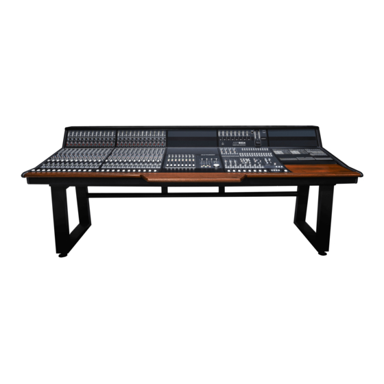
Overview... - Page 9 The ASP8024 Heritage Edition largely features the same smooth, clean sound as the original Audient console design with its 24 Buses, 12 Auxes and 2 Cue Sends. However, we have made several key enhancements including John HardyTM 990C summing amplifiers, as well as the RETRO IRON Output Card, offering tonal options on your Mix Output.
-
Page 10: Part 1: Console Functions
Console Functions Part 1... -
Page 11: Console Layout
Console Layout... -
Page 12: Input Module
Input Module... -
Page 13: Mic & Line Inputs
Mic & Line Inputs preamps ASP8024-HE METERS. The Meters show the level coming into both the Mic/Line Input and the DAW/Tape Returns transformerless, eight transistor design to provide enabling you to set a healthy signal level. They are a fast, clean sound with a little bit of colour when scaled in dBu. -
Page 14: Routing And Auxiliaries
Routing and Auxiliaries The routing of the ASP8024-HE allows you to send the signal of any given channel to any of the 24 Multi- track Buses, giving you a huge amount of flexibility at both the tracking and mixing stage. Up to 12 Auxes and 2 Cue Sends allow you to easily utilise outboard effects and control over artist foldback. -
Page 15: Equaliser 1513
Equaliser ASP8024-HE features the classic David Dearden 4-Band console Equaliser on every channel. Offering two dual-band equalisers that can be split individually to the Short (SF) or Long (LF) Fader paths. Shelves IN switches the Shelf EQ into the signal path. SF switches the Shelf EQ to the short fader path (independent of Parametric EQ). -
Page 16: Short Fader (Sf)
Short Fader (SF) ASP8024-HE is an inline console. This means that there are both input and monitoring signal paths on the same channel. By default, the Short Fader contains the input signal, however you can use the channel flip switch to switch to the tape signal. Don’t forget that you can assign the Aux/Cue Sends and EQ to the Short Faders by pressing the SF buttons. -
Page 17: Long Fader (Lf)
Long Fader (LF) The Long Fader operates on the LF signal path and is mainly used for creating the monitor mix and the final stereo mix. The fader is expected to operate around the 0dB mark with 10dB of gain in hand, allowing the signal to be increased or decreased in level. -
Page 18: Master Module
Master Module... -
Page 19: Stereo Efx Inputs
Stereo EFX Inputs The Stereo EFX Inputs allow stereo signals to be brought back into the console from an effect unit without using up a complete channel strip. Often stereo signals can only be routed to the stereo mix, however, the ASP8024-HE stereo inputs allow routing back to the Multi-track in addition to the mix. -
Page 20: Bus Trims & Aux Masters
Bus Master Trim The Bus Master Trims are the final stage of level control dB KNOB allows you to adjust the overall level of a particular Multi-track Bus from -10dB to +10dB. over the signals routed to the Multi-track Bus outputs. Each Bus has a Level Trim although for the purposes of this manual only a few are shown in the accompanying diagram. -
Page 21: Cue & Aux Masters 2119
Cue & Aux Masters The auxiliary masters control the overall level of dB KNOB Allows you to adjust the overall level of a Cue or the auxiliary outputs. A balance or mix can thus be Aux from -inf to 0dB. created by using the controls on the channel strips and the overall level adjusted by using the auxiliary 0dB MARK... -
Page 22: Subgroups
Subgroups In addition to routing signal to the Multi-track, the first eight buses are also sent to the 8 Sub Groups. Each sub group has a Pan control, Solo and Cut switches with a fader controlling the group output level. The Sub Groups have insert points located on the rear panel of the console allowing external processing to be patched in. -
Page 23: Heritage Output Card 2321
Heritage Output Card Inspired by the consoles David Dearden worked on and built throughout his career, the Heritage Output Card provides tonal shaping options on your Mix Bus Output. BUS LINK (DFA) When the optional 48 Channel LOW BUMP adds a slight boost to the low-end, Bus Mod is fitted to the console, pressing the Bus around 60Hz, which helps push the kick and bass Link button links the two 24ch buses together... -
Page 24: Bus Compressor
BUS Compressor THRESHOLD Sets the minimum amplitude needed for the Compressor circuit to kick in. GAIN MAKE-UP Adds gain to the output of the Compressor to compensate for the level lost from the dynamic range reduction. ATTACK Sets how long the Compressor takes to react once a signal passes the threshold level. -
Page 25: Master Fadar
Master Fader MASTER FADER. The Master Fadar is used to control the stereo output of the console. 0dB MARK. Unlike the Long Faders, it is calibrated with the 0dB mark at the main purpose of this fadar is to create a fade at the end of a track. Under normal operating conditions, the fader should always be set at maximum. -
Page 26: Control Room
Control Room Monitoring SOURCE SELECT BUTTONS. Allows you to select which source you would like to monitor in the control room. Mix takes audio from the Mix Bus and Ext 1-3 takes audio from the three external inputs found in the Master Section rear connector panel. -
Page 27: Live Room & Foldback
Live Room & Foldback SOURCE SELECT The Studio Loudspeaker and Artist Foldback section allow you to route signal to performers from various • EXT 1 sources on the console. In all cases, the same Takes signal from External Input 1. sources are available. -
Page 28: Communications
Communications Talkback is used to communicate with the studio, the foldback system, or the group outputs of the console. Note that the talkback to the foldback and studio loudspeaker systems will work even when their respective volume controls are turned down. In all cases, pressing a talkback button will cause the control room monitors to dim. -
Page 29: Master Meters
PSU is, then it indicates that there is an issue and Groups. we would recommend contacting us at: support@ audient.com TALKBACK MIC CONNECTOR. Use this to connect any standard microphone for talkback use. The HEADPHONE OUTPUT. The ASP8024-HE includes... -
Page 30: Oscillator & Solo
Oscillator & Solo The 4-Frequency Oscillator can be assigned either to the Multi-Track or the Stereo Mix Bus. The level is adjustable and when not in use, the Oscillator should be completely turned off. FREQ HZ. Using the two buttons, you can select from 40Hz, 1kHz, 10kHz or 15kHz for the Oscillator frequency using the combinations shown on the console. -
Page 31: Connector Panels
Connector Panels... - Page 32 Connector Panels The Connector Panels are the points at which the ASP8024-HE connects to the rest of the Studio. The inputs and outputs use advanced, electronically balanced or ground sensing topologies and are fitted with extensive RFI rejection networks. All signal interfaces are also fully protected against accidental misuse, e.g.
- Page 33 Connector Panels MAIN. Connect your main monitors here. This output STUDIO LOUDSPEAKERS. Here you can connect a is at line level so you will need an amplifier for passive pair of loudspeakers which can be used to address artists in the live room. Again this is line level and an monitors.
- Page 34 Connector Panels MIX OUTS 1,2,3. After the Master Fader, the stereo Mix Bus is sent to three Mix Outputs. These can be sent to anything that is capable of capturing a stereo signal. Having three separate Mix Outputs means you can capture up to three copies of the mix at the same time.
- Page 35 Connector Panels This panel contains the connectors for the Multi-track Bus Outputs. Rather than having individual connectors for each output, multi-pole connectors are used for fast and easy installation. The Multi-track Bus Outputs are split across 3 connectors, each carrying the outputs for 8 tracks. The Sub Group Outputs are on a fourth connector.
-
Page 36: Power Supply
Power Supply The console is powered by the ASP8120 Ultra, rack-mounted power supply. On the front you will find the power switch for the entire console, three LED indicators and the +48V fuse. The power supply uses extremely low noise fans To connect the console’s power cable, simply push the and transformers, meaning that the PSU can be connector into the socket and then pull the two retaining... -
Page 37: Part 2: Using Asp4816-He
Using ASP4816-HE Part 2... -
Page 38: Introduction
Introduction Recording is generally a three stage process made up of the tracking stage, the editing stage and then the mixing stage. The tracking stage consists of capturing the audio onto a storage medium. Traditionally audio was captured onto multi-track tape, however now the majority of people will use a Digital Audio Workstation (DAW) such as Logic or Pro Tools. -
Page 39: Tracking
In a similar vein, you can use the Short Fader to reduce the output, allowing you to increase the gain of the preamp. Although the Audient preamp design is relatively clean, it does start to tighten up and get slightly ‘warmer’ as you start to push it harder. Again, while this isn’t suitable for all situations, it can be a great way of adding additional richness or body to a recording. -
Page 40: Foldback
Foldback You can use ASP8024-HE’s two Cue Mixes, to allow musicians to hear the live input and click/guide tracks from your session. To bring a click/guide track onto the console, it needs to be sent to the DAW/Tape Returns on a channel (or multiple channels). This brings the signal onto the LF path of that channel. -
Page 41: Mixing
Mixing Getting Audio From DAW to Console Recorded tracks should be brought back onto the console using the DAW/Tape Returns, which come in on the Long Faders by default. Ensuring that the MTR flip buttons are disengaged, signal should appear on the long meters for each active channel strip. Engage the Mix buttons for the Long Faders and bring up the faders to 0dB for channels that are in use. -
Page 42: Inserts And Auxiliaries (Outboard)
Inserts & Auxiliaries (Using Outboard Equipment) There are a few different ways to connect outboard equipment to the desk, depending on how you want the outboard to affect your audio. The first way is to add the outboard gear in the channel insert point. -
Page 43: Adding Mix Bus Compression
Adding Mix Bus Compression After the insert is the Mix Bus Compressor, a Soft Knee VCA compressor, optimised for Mix Bus use. To insert the compressor into the Mix bus simply press the IN button. The Threshold controls at which amplitude the Compressor begins to compress the signal. As it is reduced, more of the signal will be compressed. -
Page 44: Part 3: Optional Extras & Modules
Optional Extras & Modules Part 3... -
Page 45: Patchbay
Patchbay This section of the manual explains the functionality OUT. This is the signal from the Multi-track Bus Outputs. This is available for each Multi-track Bus of the optional Patchbay Module and how it relates from 1 to 24. to the features explained previously in the manual. REC A, B. - Page 46 Tape Return Channel Path The Tape Return path is the signal coming back The Channel Path, is the signal coming from the from either your DAW or tape machine. microphones and instruments into the desk. PLAY A is the signal coming directly from the DEV OUT Stands for device out and allows you playback device.
- Page 47 Sub Group Inserts and Outputs SEND/RET. Each Sub Group has its own insert point allowing you to send the Sub Group signal to outboard gear. OUT. The output of the Sub Group can be found here, allowing you to send the Sub Group signal anywhere on the Patchbay.
- Page 48 Mix Outputs MIX L, MIX R. The sends for the left and right 1L, 1R, 2L, 2R, 3L, 3R. The left and right outputs of each Mix Output, labelled accordingly (1L = Mix sides of the stereo Mix Bus. This comes after the Output 1, Left Channel).
- Page 49 Parallels Studio Loudspeaker Any signal patched into one of the Parallel Jacks L, R. The left and right channels of the Studio Loudspeaker send. will be sent out of the other three jacks allowing signals to be duplicated. Do not plug in more than AMP.
- Page 50 Speaker Outputs L, R. Contains the signal for the left and right AMP. A direct output to any equipment connected to the Speaker Connectors on the channels of the Speaker Outputs. rear of the console. In most cases this will be an amplifier, either a stand alone unit or built into a pair of active monitors.
- Page 51 Level Converters The level converters take a professional +4dB signal and passively convert it to -10dB for patching in consumer level devices. Please note that the conversion can only bring the signal level down and can’t be used in reverse. Tie Lines There are 144 Tie Lines giving plenty of space to add outboard gear.
-
Page 52: Dlc Module
DLC Module For those who have the Dual Layer Control Module, there is a separate manual section which can be found at the end of this manual. -
Page 53: Producer's Desk
Producer’s Desk The Producer’s Desk provides extra real estate on your console, letting you place a keyboard, mouse or even a control surface at the centre of your console or off to one side for an assistant. Traditionally the producer would sit at the PD to take session notes or annotate music scores alongside the engineer. -
Page 54: Channel Bus Mod & Dfa
48 BUS Mod & DFA Studio Speakers and Foldback The 48-Bus Mod provides an extra set of Multi- track Bus Outputs, forming Multi-track Buses 25-48. Where the first 24 channels of the console have access to buses 1-24, and subsequent channels have access to 25-48. -
Page 55: Vesa Screen Mount
VESA Screen Mount The VESA screen mount provides both 75 and 100mm mounting options for TFT screens up to 19”. Simply screw the VESA mount onto the back of the screen using the four screws provided, then re-attach the system to the ball joint on the console, making sure it is tightly fixed. -
Page 56: Part 4: Further Information
Further Information... -
Page 57: Warranty
The warranty covers faults due to defective materials used in manufacture and faulty workmanship only. During this warranty period Audient will repair or at its discretion replace the faulty unit provided it is returned carriage paid to an authorised Audient service centre. We will not provide warranty repair if in our opinion the fault has resulted from unauthorised modification, misuse, negligence, act of God or accident. -
Page 58: Registration
Registration Please register your console on our website to receive useful information about ASP8024 Heritage Edition including educational resources, usage tips and more. Registration is also useful for us to be able to identify your product, and increase the speed at which we are able to provide technical support. -
Page 59: Console Specifications
Console Specifications Frequency Response Maximum Output into 2kΩ MIC INPUT TO MIX OUTPUT ±0.3dB (20Hz to 20kHz MIX OUTPUT > +26dBu with 6 to 40dB gain). BUS OUTPUT > +26dBu LINE INPUT TO MIX OUTPUT ±0.3dB (20Hz to 20kHz AUX OUTPUT >... - Page 60 Retro Iron Heritage The Heritage Card was designed and built with world class LM4562 operational amplifiers (EQ stages) and a discrete Class-AB RETRO IRON output stage based upon the best US & UK designs from the early 1970’s. Taking influence from two consoles that David Dearden modified and serviced at Advision Studios in London during his arrival as in-house technician, these consoles became part of the sound of recording for clients such as David Bowie, Emerson Lake &...
- Page 61 Headphone Amplifier ASP8024 Heritage Edition comes with a high-current reference headphone amplifier provided as the ALT3 monitor output destination. The new design features a 250mA high current output stage based upon class leading Burr-BrownTM and LM4562 high-speed amplifiers. The output is entirely D.C coupled with very low output impedance for all types of headphones and there is only...
-
Page 62: Glossary
Glossary... - Page 63 This allows after fade (post fade) signals to be heard on the monitors and viewed on the main stereo meters. Auxiliaries Sometimes known as auxiliary sends these are used as secondary mix buses. The mixes created on these buses are then used to feed effect units or are fed back to the performers as a foldback feed.
- Page 64 Equaliser Equalisers are what would be referred to as tone controls on consumer equipment. Equalisers are divided into a number of bands - 4 in this case. There is scope to adjust high and low frequencies and two bands of middle (mid) frequencies. The high and low frequency sections are shelving and the turnover frequency is switchable.
- Page 65 Insert points Insert points allow the signal path to be broken allowing the insertion of some signal processing device. The device inserted is then in series with the signal path. When not required the device can either be switched out using the INSERT switch or unplugged from the console. The Long fader is normally used to feed the mix.
- Page 66 Short for panoramic potentiometer this control places a mono source signal onto the stereo bus. The proportion of signal fed to the left and right buses is variable (using the pan control) and alters the spatial position of an instrument within the mix. Thus a number of channels can all be panned to different spatial positions.
- Page 67 Shift This allows the number of routing switches to be reduced by doubling the function of each switch. With Shift unpressed routing is possible to tracks 1 through 8. With Shift pressed routing to tracks 9 through 16 is possible. Solo in place This is a method of previewing the signal in a channel and works by cutting all the signals feeding the stereo bus other than the one(s) being solo’d.
-
Page 68: Part 5: Dlc Manual
Dual Layer Control (DLC) Manual V1.0... - Page 69 Contents DLC Summary Installation Mac Installation Routing and Auxiliaries Equaliser DLC Operation Control Surface Interface Audio Routing VCA Functionality Faderlink Interface Analogue Automation Firmware & Support...
-
Page 70: Dlc Summary
DLC Summary The Dual Layer Control Module gives you control over analogue and digital worlds from the heart of the console. In the analogue layer, it provides intuitive analogue automation as well as an extra set of line inputs and outputs. In the DAW layer, it provides a powerful array of DAW control features, right at your fingertips. -
Page 71: Mac Installation
Mac Installation This section goes through the installation process for the DLC module on your computer, allowing you to make use of the Analogue Automation and Control Surface functionality. Physical Connection To physically connect DLC to your computer, plug a standard CAT5 Ethernet cable into the port located above the DLC Network sticker on the rear of the console, and the other end into your computer (or router/switch). - Page 72 Networking Theory On a network, devices must have a unique “address” to ensure they can communicate, this is known as an IP address. You will need to decide whether your network will automatically assign IP addresses to connected devices, or if you will manually assign them yourself.
- Page 73 Setting Manual IP Addresses If you aren’t using DHCP to automatically set IP addresses, you must set them manually on the DLC and Mac to ensure the two devices are communicating correctly. System Preferences > Network > Ethernet Tab > Configure IPv4 Manually Example: Choose a unique IP address by changing ‘X’...
- Page 74 Page right again to reach the IP address screen and use the encoders to set the IP address to: 192 . 168 . 100 . X (ensuring that ‘X’ is different to that of the computer). On the following pages, set the Subnet Mask 255 .
- Page 75 Windows Installation Physical Connection To physically connect DLC to your computer, plug a standard CAT5 Ethernet cable into the port located above the DLC Network sticker on the rear of the console, and the other end into your computer (or router/switch). AuNet App To achieve communication between DLC and the PC, the AuNet app is needed.
- Page 76 Networking Theory On a network, devices must have a unique “address” to ensure they can communicate, this is known as an IP address. You will need to decide whether your network will automatically assign IP addresses to connected devices, or if you will manually assign them yourself.
- Page 77 Example: Choose a unique IP address by changing ‘X’ to a number between 1-254, the number must be different on the DLC module and the computer: 192 . 168 . 100 . X Set the Subnet Mask to: 255 . 255 . 255 . 0 We recommend leaving the Default Gateway settings blank.
- Page 78 Page right again to reach the IP address screen and use the encoders to set the IP address to: 192 . 168 . 100 . X (ensuring that ‘X’ is different to that of the computer). On the following pages, set the Subnet Mask 255 .
- Page 79 Faderlink Installation Faderlink is a simple and elegant solution to the Download the Faderlink plugin installer from our website: audient.com/products/consoles/ASP8024- problem of integrating analogue automation within HE/downloads Digital Audio Workstation projects, without the need for a dedicated console computer. Faderlink Close your Digital Audio Workstation applications.
-
Page 80: Dlc Operation
DLC Operation... - Page 81 The control surface functions operate differently depending on your choice of DAW. For instructions on how to use the control features within your workstation, please refer to the DAW specific control surface manuals found online at: audient.com/products/consoles/ASP8024-HE/downloads DAW Meters Encoder & Display...
-
Page 82: Control Surface Interface
Audio Routing DLC has eight line inputs and outputs, labelled the DLC VCA Inputs/Outputs. These are accessible on the rear of the console on DB25 connectors (location depends on console configuration). METER. Displays the level of the signal coming from the source, unless the DAW Meters switch on the control surface is engaged. -
Page 83: Vca Functionality
VCA Functionality There are two buttons on the right section of DLC that are applicable in the Analogue Layer when using analogue automation. AUTO SAFE Press Auto Safe then engage the Select button on any channel that you want to completely isolate from automation control. -
Page 84: Faderlink Interface
Faderlink Interface CHANNEL CUT BUTTON. Cuts the audio for this DEVICE MENU. Select the appropriate device from channel. This mimics the Cut Button on the selected the menu. channel on the DLC module. MIDI IN MENU*. Select the MIDI Input for CHANNEL FADER. -
Page 85: Analogue Automation
Analogue Automation For analogue automation functionality, first ensure the DLC has the Analogue Automation Mode set to Faderlink in the first page of the Setup Menu, then follow these instructions for each DLC channel you want to automate: Set the desired audio routing using the Source and Set the channel number to the VCA fader you Dest buttons. -
Page 86: Firmware & Support
By registering your console, you can be notified via email when new updates are made available. Please visit the Registration Section of the main ASP8024-HE manual for more information. If you are experiencing any issues, please contact our support team via email at: support@audient.com Audient Ltd Aspect House Herriard Hampshire...
Need help?
Do you have a question about the ASP8024 HERITAGE EDITION and is the answer not in the manual?
Questions and answers