
Related Manuals for Audient ASP8024


Summary of Contents for Audient ASP8024
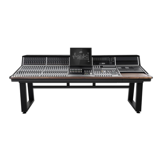
- Page 1 ANALOGUE RECORDING CONSOLE User Manual v1.3 connect with us. .audient.com audient.com facebook.com/audient twitter.com/audientworld youtube.com/audienthampshire instagram.com/audientworld...
- Page 2 TH AN K YOU F OR P UR C H AS IN G YO UR AS P 8 0 24 H ERI TAGE E DI T IO N With the ASP8024 in production for nearly 20 years, and thousands of consoles in use around the world based upon David Dearden’s legendary circuit blocks, we’ve returned to his roots to release the definitive version...
-
Page 3: Table Of Contents
PART IV: FURTHER INFORMATION Oscillator & Solo Warranty Connector Panels Registration Power Supply Console Specifications Glossary PART II: USING ASP8024-HE Introduction Inline Architecture Tracking Getting Started The Multi-Track Buses *For those with a DLC module, a separate DLC manual can be found at rear of this manual. -
Page 4: Safety Warnings
Safety Warnings Please read all of these instructions and save them for later reference before attempting to connect the ASP8120 Ultra PSU to the Mains AC power source. To prevent electrical shock and fire hazard, follow all the warnings and instructions marked on the rear of the ASP8120 Ultra PSU. •... -
Page 5: Console Summary
RETRO IRON Output Card, offering tonal options on your Mix Output. The ASP8024-HE is a fully inline console allowing you to start building your mixes as you’re tracking. By utilising the Long and Short Faders simultaneously you can create separate record and monitor balances on the same channel strip, all while being able access the consoles split-able EQ and Aux Sends. -
Page 7: Part I: Console Functions
PART I CONSOLE FUNCTIONS This part of the manual will take you through the functionality of each section and individual controls on the console. We recommend referencing the following pages when you are unsure on how to use a feature or parameter, or would simply like to further understand specific controls found on the console. -
Page 8: Console Function Overview
console FUNCTION OVERVIEW... -
Page 9: Input Module
IN P UT M OD U L E This section takes you through the Input Module, starting from the Meters, all the way down to the Long Faders. Each channel strip is identical in this module, therefore the following explanations can be applied to every channel strip. -
Page 10: Mic & Line Inputs
Mic & Line Inputs The preamps of the ASP8024-HE use a transformerless, NOTE eight transistor design to provide a fast, clean sound with 0VU = +4dBu = 1.23Vrms = -14dBFS a little bit of colour when pushed. An insert on both the... -
Page 11: Bus Routing & Auxes
BUS Routing & Auxes The routing of the ASP8024-HE allows you to send the signal of any given channel to any of the 24 Multi-track Buses, giving you a huge amount of flexibility at both the tracking and mixing stage. Up to 12 Auxes and 2 Cue Sends allow you to easily utilise outboard effects and control over artist foldback. -
Page 12: Equalisers
Equalisers ASP8024-HE features the classic David Dearden 4-Band console Equaliser on every channel. Offering two dual-band equalisers that can be split individually to the Short (SF) or Long (LF) Fader paths. SHELVES Switches the Shelf EQ into the signal path. -
Page 13: Short Faders
Short FaderS ASP8024-HE is an inline console. This means that there are both input and monitoring signal paths on the same channel. By default, the Short Fader contains the input signal, however you can use the channel flip switch to switch to the tape signal. -
Page 14: Long Faders
LONG FaderS The Long Fader operates on the LF signal path and is mainly used for creating the monitor mix and the final stereo mix. The fader is expected to operate around the 0dB mark with 10dB of gain in hand, allowing the signal to be increased or decreased in level. -
Page 15: Master Module
M A ST ER M OD UL E The following section goes through the Master Module, which handles mix bus processing, monitoring, and communications among other things. -
Page 16: Stereo Efx Inputs
Often stereo signals can only be routed to the stereo mix, however, the ASP8024-HE stereo inputs allow routing back to the Multi-track in addition to the mix. -
Page 17: Bus Trims & Aux Masters
bus trims & aux masters The Bus Master Trims are the final stage of level control over the signals routed to the Multi-track Bus outputs. Each Bus has a Level Trim although for the purposes of this manual only a few are shown in the accompanying diagram. -
Page 18: Sub Groups
sub groups In addition to routing signal to the Multi-track, the first eight buses are also sent to the 8 Sub Groups. Each sub group has a Pan control, Solo and Cut switches with a fader controlling the group output level. The Sub Groups have insert points located on the rear panel of the console allowing external processing to be patched in. -
Page 19: Heritage Output Card
Heritage output card Inspired by the consoles David Dearden worked LOW BUMP on and built throughout his career, the Heritage Low Bump adds a slight boost to the low-end, Output Card provides tonal shaping options on around 60Hz, which helps push the kick and your Mix Bus Output. -
Page 20: Bus Compressor
bus compressor THRESHOLD RATIO Sets the minimum amplitude needed for the Sets the amount of level reduction once the Compressor circuit to kick in. amplitude passes the threshold level. 2:1 decreases it by a factor of 2 where as 10:1 GAIN MAKE-UP decreases it by a factor of 10. -
Page 21: Master Fader
Master fader MASTER FADER The Master Fader is used to control the stereo output of the console. 0dB MARK Unlike the Long Faders, it is calibrated with the 0dB mark at the top, as the main purpose of this fader is to create a fade at the end of a track. Under normal operating conditions, the fader should always be set at maximum. -
Page 22: Control Room
Allows you to cut either the left, right or both MAIN monitors. Sends your selected source to the device connected to the Main Output of the ASP8024- HE, normally the main monitors. Reduces the level of the main output by a set amount. Dim will be switched in automatically... -
Page 23: Live Room & Foldback
live room & foldback The Studio Loudspeaker and Artist Foldback section allow you to route signal to performers from various sources on the console. In all cases, the same sources are available. SOURCE SELECT • EXT 1 Takes signal from External Input 1. •... -
Page 24: Communications
ARTIST FOLDBACK Sends the talkback to the Artist Foldback Mix. REMOTE TALKBACK ASP8024-HE has the option to control the Artist Foldback and Studio Loudspeaker talkback via latching foot switches (not provided). This lets you talk to artists and continue using the console without having to reach for the talkback controls. -
Page 25: Master Meters
HEADPHONE OUTPUT talkback use. The connector has +48V Phantom Power for use with condenser mics. Phantom The ASP8024-HE includes a reference grade Power can be switched off by removing the Headphone Amplifier which is accessed by jumper at LK1 on the Master Meter circuit routing the audio to the ALT 3 outputs in the board. -
Page 26: Oscillator & Solo
OSCILLATOR & SOLO The 4-Frequency Oscillator can be assigned either to the Multi-Track or the Stereo Mix Bus. The level is adjustable and when not in use, the Oscillator should be completely turned off. FREQ HZ Using the two buttons, you can select from 40Hz, 1kHz, 10kHz or 15kHz for the Oscillator frequency using the combinations shown on the console. -
Page 27: Connector Panels
CON NE CTOR PA N E L S The Connector Panels are the points at which the ASP8024-HE connects to the rest of the Studio. The inputs and outputs use advanced, electronically balanced or ground sensing topologies and are fitted with extensive RFI rejection networks. -
Page 28: Connector Panels
connector panels The rear mounted Connector Panel is where the input, output and insert point connectors are located. The Microphone Input uses an XLR Connector, while the Line Input, Tape Input and the Insert Sends and Returns use Tip, Ring and Sleeve jacks. Microphones or other low level equipment can be connected to this input. - Page 29 connector panels MAIN STUDIO LOUDSPEAKERS Connect your main monitors here. This output Here you can connect a pair of loudspeakers is at line level so you will need an amplifier for which can be used to address artists in the live passive monitors.
-
Page 30: Connector Panels
connector panels SUB GROUP INSERTS 1-8 This panel carries the connectors for the Sub Group Insert Points. There are 8 Sub Groups and each has a Send Output and a Return Input. Signal is always present on the Send Output. If required, the Insert Returns could be used as very basic inputs to the stereo mix bus during mixdown, from a submixer or sampler for... -
Page 31: Connector Panels
connector panels This panel contains the connectors for the Multi-track Bus Outputs. Rather than having individual connectors for each output, multi- pole connectors are used for fast and easy installation. The Multi-track Bus Outputs are split across 3 connectors, each carrying the outputs for 8 tracks. -
Page 32: Power Supply
power supply The console is powered by the ASP8120 Ultra, The LED indicators show the current status rack-mounted power supply. On the front you of the +18V, -18V and +48V Power rails, if will find the power switch for the entire console, the LEDs are lit then it means that the rails three LED indicators and the +48V fuse. -
Page 33: Part Ii Using Asp8024-He
PART II USING ASP8024-HE This part of the manual explains how the features of the console can be used in an typical recording session. If you are new to recording or even just new to a console workflow then this section will give you the starting points you need to track and mix a project. -
Page 34: Introduction
The first step is to get a signal into the analogue mix bus processing of the ASP8024- console from the microphone or instrument. To do this, connect the microphone or instrument to the Mic/Line Inputs of your console. -
Page 35: The Multi-Track Buses
THE MULTI-TRACK BUSES FOLDBACK For simple sessions, it is typical to route the SF You can use ASP8024-HE’s two Cue Mixes, channel path to its corresponding Multi-track to allow musicians to hear the live input and Output using the Bus Routing Matrix. This click/guide tracks from your session. -
Page 36: Mixing
SUB GROUPS channel insert point. This means the outboard can only affect the channel it is placed on. ASP8024-HE has eight subgroups, which Connect your outboard gear between the allows you to group certain tracks together insert send and return, then press the ‘Insert and give you control over their overall level In’... -
Page 37: The Mix Bus
The Mix Bus is the two channel bus that your compressed. The Ratio controls by how much mix is summed into. On the ASP8024-HE, the signal above the threshold is reduced. A the summing bus is active and uses a pair of... -
Page 39: Part Iii: Optional Extras & Modules
PART III OPTIONAL EXTRAS AND MODULES This part of the manual looks in detail at the optional extras and modules that you might have included when configuring your console. -
Page 40: Patchbay
PATCHBAY This section of the manual explains the functionality of the optional Patchbay Module and how it relates to the features explained previously in the manual. - Page 41 patchbay REC A, B This is the signal from the Multi-track Bus These are the outputs to the 24 track recording Outputs. This is available for each Multi-track medium, be that a DAW or a tape machine. Each Bus from 1 to 24. Multi-track Bus has a separate A and B output, which allows you to simultaneously track to two separate recording mediums.
- Page 42 patch bay SUB GROUP INSERTS AND OUTPUTS SEND/RET Each Sub Group has its own insert point allowing you to send the Sub Group signal to outboard gear. The output of the Sub Group can be found here, allowing you to send the Sub Group signal anywhere on the Patchbay.
- Page 43 patch bay MAIN MIX INSERTS SEND The sends are found after the Heritage Card in the signal chain, so if RETRO IRON is engaged, it will be present on the sent signal. The return comes before the Bus Compressor, so any signal coming into the return will be compressed if the Compressor is switched in.
- Page 44 patch bay PARALLELS Any signal patched into one of the Parallel Jacks will be sent out of the other three jacks allowing signals to be duplicated. Do not plug in more than one signal send at the same time as this will short the outputs together! STUDIO LOUDSPEAKER L, R...
- Page 45 patch bay SPEAKER OUTPUTS L, R Contains the signal for the left and right channels A direct output to any equipment connected of the Speaker Outputs. to the Speaker Connectors on the rear of the console. In most cases this will be an amplifier, either a stand alone unit or built into a pair of active monitors.
- Page 46 patch bay LEVEL CONVERTERS The level converters take a professional +4dB signal and passively convert it to -10dB for patching in consumer level devices. Please note that the conversion can only bring the signal level down and can’t be used in reverse. TIE LINES There are 144 Tie Lines giving plenty of space to add outboard gear.
-
Page 47: Dlc Module
dlc module For those who have the Dual Layer Control Module, there is a separate manual section which can be found at the end of this manual. -
Page 48: Producer's Desk
producer's desk The Producer’s Desk provides extra real estate on your console, letting you place a keyboard, mouse or even a control surface at the centre of your console or off to one side for an assistant. Traditionally the producer would sit at the PD to take session notes or annotate music scores alongside the engineer. -
Page 49: Channel Bus Mod & Dfa
48 BUs mod & DFA The 48-Bus Mod provides an extra set of Multi-track Bus Outputs, forming Multi-track Buses 25-48. Where the first 24 channels of the console have access to buses 1-24, and subsequent channels have access to 25-48. Buses 25-48 do not have access to bus master trims and so exit the console at unity gain. -
Page 50: Vesa Screen Mount
Vesa screen mount The VESA screen mount provides both 75 and 100mm mounting options for TFT screens up to 19”. Simply screw the VESA mount onto the back of the screen using the four screws provided, then re-attach the system to the ball joint on the console, making sure it is tightly fixed. -
Page 51: Cable Entry Meter Pod
cable entry meter pod The Cable Entry Meter Pod allows you to feed cables through the console offering a much neater console surface. To wire cables through the console: 1. Unscrew a rectangular blanking panel found underneath the console. 2. Carefully unscrew and lower the rear connector panel, making sure to remove the cable hooks as well. -
Page 52: Asp510 Mod
Pressing a Solo on the console will switch the input of the ASP510 to the Control Room Output of the ASP8024-HE console. A guide track can be fed to the ASP510 via console Auxes 7-8, and monitored using the Guide On button on the ASP510. -
Page 53: Part Iv: Further Information
PART Iv FURTHER INFORMATION This part of the manual gives further information about the console, including warranty, registration, specifications, and manual glossary... -
Page 54: Warranty
The warranty only covers faults due to defective materials used in manufacture and faulty workmanship. During this warranty period Audient will repair or, at its discretion, replace the faulty part. We will not provide warranty repair if in our opinion the fault has resulted from unauthorised modification, misuse, negligence, act of God, or accident. -
Page 55: Registration
Registration Please register your console on our website to receive useful information about ASP8024 Heritage Edition including educational resources, usage tips and more. Registration is also useful for us to be able to identify your product, and increase the speed at which we are able to provide technical support. -
Page 56: Console Specifications
CONSOLE Specifications FREQUENCY RESPONSE Mic Input to Mix Output ±0.3dB (20Hz to 20kHz with 6 to 40dB gain) Line Input to Mix Output ±0.3dB (20Hz to 20kHz with 0dB gain) THD + N Mic XLR Input to any Output < 0.005% @ 1kHz, +22dBu Output Line Input to any Output <... - Page 58 RETRO IRON HERITAGE CARD FREQUENCY RESPONSE RETRO IRON Engaged on Main Mix ±0.1dB (10Hz to 80kHz) HARD-WIRE BYPASS Relay Switched - No Loading Effects THD + N 0dBu into 600Ω < 0.016% @ 1kHz (2nd & 3rd) +24dBu into 600Ω <...
- Page 60 < -80dB 10Hz to 10kHz, typ. -82dB @ 1kHz OUTPUT IMPEDANCE < 10Ω DC Coupled ASP8024 Heritage Edition comes with a high-current reference headphone amplifier provided as the ALT3 monitor output destination. The new design features a 250mA high current output stage based upon class leading Burr-Brown and LM4562 high-speed amplifiers.
-
Page 62: Glossary
glossary 48 Volt Phantom Power After Fader Listen Alternate (speaker) Auxiliary Bandwidth of EQ (AKA the “Q-value”) CH FLIP Channel Flip Digital Audio Workstation dBFS Decibels relative to digital full scale Standard unit in audio level measurement DEST Destination Device Does F*** All Dual Layer Control External Effects...
Need help?
Do you have a question about the ASP8024 and is the answer not in the manual?
Questions and answers