Table of Contents

Related Manuals for Atlas Copco Dynapac F2500W


Summary of Contents for Atlas Copco Dynapac F2500W
- Page 1 OPERATION & MAINTENANCE Paver Finisher Dynapac F2500W / F2500WS Type 896 4812023948 (A5) 04-0516 Keep for later use in document compartment Valid for: _________________ - _________________ _________________ - _________________...
- Page 2 www.atlascopco.com...
-
Page 3: Table Of Contents
Table of contents Preface ..................1 General safety instructions ................ 2 Laws, guidelines, accident prevention regulations ........2 Safety signs, signal words ................. 3 "Danger"! ....................3 "Warning" ! ..................... 3 "Caution" ! ....................3 "Note" ! ....................3 Other supplementary information ............... 3 Warnings .................... - Page 4 CE marking ....................25 Instructive symbols, prohibitive symbols, warning symbols ..... 26 Danger symbols ..................27 Further warnings and operating instructions ..........28 Identification label for the paver finisher (41) ........30 Engine type plate ..................31 EN standards ................... 32 Continuous sound pressure F2500W, Cummins QSB 6.7-C173 .....
- Page 5 Operation ................. 1 Operating elements on the paver finisher ..........1 Control elements on the operator's control station ........1 Protective roof (o) .................. 2 ....................... 2 Ladder ....................4 Storage space ..................4 Control platform, moveable (o) .............. 5 Control platform lock (o) ................
- Page 6 Fire extinguisher (o) ................37 First-aid kit (o) ..................37 Rotary beacon (o) ................38 Fuelling pump (o) ................. 39 Illuminated balloon (o) ................. 40 Installation and operation ..............41 Maintenance ..................42 Replacing the lamp ................42 Truck Assist (o) ..................43 Mode of operation ..............
- Page 7 When work is finished ................35 Malfunctions ..................... 36 Error code query for engine ..............36 Output of numerical code ..............38 Error codes ....................40 Problems during paving ................47 Malfunctions on the paver finisher or screed ........... 49 Set-up and modification ............
- Page 8 Maintenance ................1 Notes regarding safety ................1 Maintenance review ..............1 Maintenance review ................... 1 Maintenance - conveyor ............1 Maintenance - conveyor ................1 Maintenance intervals ................3 Points of maintenance ................4 Chain tension, conveyor (1) ..............4 Conveyor drive - drive chains (2) ............
- Page 9 Maintenance - hydraulic system ..........1 Maintenance - hydraulic system ..............1 Maintenance intervals ................3 Points of maintenance ................5 Hydraulic oil tank (1) ................5 Suction/return flow hydraulic filter (2) ............ 7 Bleeding the filter ................... 8 Ventilation filter ..................8 High-pressure filter (3) ................
- Page 10 F100 Tests, stopping ..............1 Tests, checks, cleaning, stopping .............. 1 Maintenance intervals ................2 General visual inspection ................3 Check that the bolts and nuts fit firmly ............3 Inspection by an expert ................3 Cleaning ..................... 4 Cleaning the hopper ...................
-
Page 11: Preface
V Preface Translation of the original operating instructions. If the vehicle is to be operated safely, the information provided in these operating in- structions will be required. The information is provided in a concise, clearly structured form. The individual chapters are arranged in alphabetical order. and every chapter starts with page 1. -
Page 12: General Safety Instructions
General safety instructions Laws, guidelines, accident prevention regulations The locally applicable laws, guidelines and accident prevention regulations must al- ways be observed, even if these are not expressly named here. The user himself/herself is responsible for compliance with the resulting regulations and measures! The following warnings, prohibitive symbols and instructive symbols indicate dangers for persons, the vehicle and the environment due to residual risks when operating the... -
Page 13: Safety Signs, Signal Words
Safety signs, signal words In the safety instructions, the signal words "Danger", "Warning", "Caution", "Note" are positioned in the coloured title block. They follow a certain hierarchy; in combination with the warning symbol, they indicate the severity of the danger or the type of note. "Danger"! DANGER Danger of personal injury. -
Page 14: Warnings
Warnings Warning on a dangerous area or hazard! Failure to observe the warnings can result in life-threatening inju- ries! Warning on danger of being pulled in! In this working area/on this element there is a danger of being pulled in by rotating or conveying elements! Only carry out activities with elements switched off! Warning on dangerous electrical voltage! All maintenance and repair work on the screed's electrical system... - Page 15 Warning on danger of falling! Warning on dangers posed by batteries! Warning on hazardous or irritating substances! Warning on substances which constitute a fire hazard! Warning on gas bottles!
-
Page 16: Prohibitive Symbols
Prohibitive symbols Opening/walking on/reaching in/carrying out/setting up are prohibit- ed during operation or while the drive engine is running! Do not start engine/drive! Maintenance and repair work may only be carried out with the diesel engine shut down! Spraying with water is prohibited! Extinguishing with water is prohibited! Unauthorised maintenance is prohibited! Only qualified experts may conduct maintenance! -
Page 17: Protective Equipment
Protective equipment Locally applicable regulations may require the wearing of various safety equipment! Always observe these regulations! Wear safety goggles to protect your eyes! Wear suitable head protection! Wear suitable hearing protection to protect your hearing! Wear suitable safety gloves to protect your hands! Wear safety shoes to protect your feet! Always wear close-fitting work clothing! Wear a warning vest to be seen in time to avoid accidents! -
Page 18: Environmental Protection
Environmental protection The locally applicable laws, guidelines and accident prevention regulations for the proper recycling and disposal of waste must always be observed, even if these are not expressly named here. Water-endangering substances like: - Lubricants (oil, grease) - Hydraulic oil - Diesel fuel - Coolant - Cleaning liquids... -
Page 19: Additional Information
Additional information Also observe the manufacturer's documentation and additional doc- umentation! For example, the maintenance instructions of the engine manufac- turer Description / depiction applicable when equipped with gas heater! Description / depiction applicable when equipped with electric heat- t Used to indicate standard equipment. o Used to indicate optional equipment. -
Page 20: Ce Identification And Declaration Of Conformity
CE identification and Declaration of Conformity (only applies to machines sold in the EU/EEC) This machine has CE identification. This identification says that the machine fulfils the basic health and safety requirements pursuant to the Machinery Directive 2006/42/ EC together with all other valid regulations. The scope of supply of the machine in- cludes a Declaration of Conformity as specified in the valid regulations and amend- ments together with harmonised standards and other valid provisions. -
Page 21: Residual Risks
Residual risks These are risks that remain even if all possible measures and safety precautions have been taken to help minimise dangers (risks) or to reduce their probability and scope to zero. Residual risks in the form of - Danger to life and limb of persons at the machine - Danger to the environment posed by the machine - Damage to property and restricted output and functionality of the machine - Damage to property in the operating range of the machine... -
Page 22: Sensibly Predictable Incorrect Usage
Sensibly predictable incorrect usage Every kind of sensibly predictable incorrect usage of the machine constitutes misuse. Incorrect usage makes the manufacturer's warranty null and void: the operator bears sole responsibility. Sensibly predictable incorrect usage of the machine includes: - presence in the danger zone of the machine - transporting persons - leaving the operator's platform while the machine is operating - removing protection or safety devices... -
Page 23: A Correct Use And Application
A Correct use and application The "Guidelines for the Correct Use and Application of Paver Finishers" compiled by Dynapac are included in the scope of delivery for the present machine. The guidelines are part of the present operating instructions and must always be heeded. National regulations are fully applicable. -
Page 25: B Vehicle Description
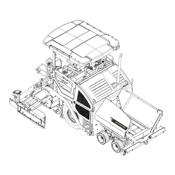
B Vehicle description Application The Dynapac paver finisher F2500W is a wheeled paver finisher which is used for paving bituminous mixed material, roll-down or lean-mixed concrete, track-laying bal- last and unbound mineral aggregates for foundations for paving. -
Page 26: Description Of Assemblies And Functions
Description of assemblies and functions Item Designation Material compartment (hopper) Truck push rollers Tube for sensor rod (direction indicator) and holder for levelling shoe Rear wheels Levelling cylinder for paving thickness Traction roller Crossbeam pull bar Paving thickness indicator Crossbeam Travel drive Auger Screed... -
Page 27: Vehicle
Vehicle Construction The paver finisher has a welded steel frame on which the individual components are mounted. The large drive wheels and the tandem front axle compensate uneven areas on the ground; the suspension of the attached screed also warrants high paving precision. The fully variable hydrostatic travel drive allows the speed of the paver finisher to be matched to all work conditions. - Page 28 Engine: The paver finisher is driven by a water cooled diesel engine. For further de- tails see the technical data and the engine's instruction manual. Traction unit: The front axle is a tandem swing axle. As the wheels are not mounted on non-uniform lifting arms, the second front wheel is subject to a heavier load on the shorter lifting arm.
- Page 29 Material compartment (hopper): The hopper inlet is equipped with a conveyor sys- tem that empties the hopper and transfers the material to the auger. The hopper can hold approx. 12.0 t. To facilitate emptying and to improve material transport, each of the lateral covers of the hopper can be hydraulically moved.
- Page 30 Levelling/slope control system: The slope control system (o) can be used to reg- ulate the traction point on the left-hand or the right-hand side with a defined difference to the opposite side. To determine the actual value, the two traction crossbeams are linked with a slope control rod.
-
Page 31: Danger Zones
Danger zones WARNING Danger for persons in the danger zone Persons in the danger zone can suffer severe or fatal inju- ries from movements and functions of the vehicle! - Never stand in the danger zone of the vehicle! - During operation, only the vehicle operator and the screed personnel are allowed on the vehicle or in the danger zone. -
Page 32: Safety Devices
Safety devices 4 5 6 7... - Page 33 Item Designation Hopper transport safeguard Screed lock, mechanical / hydraulic (o) Main switch Emergency stop button Horn Ignition key Lights Protective roof latch (o) Fire extinguisher (o) Screed warning light (o) Covers, lateral flaps, coverings Rotary beacon (o) Located on both sides of the vehicle Safe operation is only possible if the control and safety devices are functioning perfectly and if the protective equipment is fitted correctly.
-
Page 34: Technical Data, Standard Configuration
Technical data, standard configuration Dimensions (all dimensions in mm) 2125 500 425 2240 6100 6380 2055 2550 3140 3250 For screed technical data, refer to the screed operating instructions. B 10... -
Page 35: Allowed Angle Of Rise And Slope
Allowed angle of rise and slope max 15° max 15° max 15° max 15° Before operating your vehicle in an inclined position (gradient, slope, lateral inclina- tion) which is above the specified limit value, please consult the customer service de- partment for your vehicle! Permissible approach angle max 16°... -
Page 36: Weights F2500W (All Weights In T)
Weights F2500W (all weights in t) Paver finisher without screed approx. 13,2 - 14,2 Paver finisher with screed: - V5100 approx. 16,5 - 17,5 With extension parts for max. working width, additionally max.: With filled hopper approx. 13.0 additionally max. For the weights of the screed and the screed attachments, see the operating instruc- tions for the screed. -
Page 37: Performance Data F2500W
Performance data F2500W V5100TV 2.55 2.00 5.10 6.60 Transport speed 0 - 15 km/h Transport speed - reversing 0 - 15 km/h Operating speed 3 - 30 m/min Paving height -100 - 300 Max. grain size Theoretical paving performance B 13... -
Page 38: Travel Drive/Traction Unit
Travel drive/traction unit Hydrostatic drive with pump and motor, continu- Drive ously adjustable Transmission Planetary gear Speeds (see above) Drive wheels 2 x 445/80R25 (pneumatic tyres) Steered wheels 4 x 560 / 300 - 390 (elastic solid rubber tyres) Brakes Travel drive brake, hydraulic parking brake Engine F2500W Make/type... -
Page 39: Material Compartment (Hopper)
5.10 Material compartment (hopper) Volume Approx. 6.0 m = approx. 13.0 t Minimum inlet height, centre 575 mm Minimum inlet height, outside 585 mm Hopper width, outside, open 3,460 mm 5.11 Material transfer Type Dual conveyor belt Width 2 x 580mm Conveyors Left and right auger separately controllable Drive... -
Page 40: Screed Lifting Device
5.13 Screed lifting device At standstill: - Screed stop - Screed stop with pretensioning (max. pressure 50 bar) Special functions During paving: - Screed charging - Screed relieving (max. pressure 50 bar) Mechanical grade control Levelling system Optional systems with and without Slope control system 5.14 Electrical system... -
Page 41: Location Of Instruction Labels And Identification Plates
Location of instruction labels and identification plates CAUTION Danger from missing or misunderstood vehicle signs Missing or misunderstood vehicle signs pose a danger of injuries! - Never remove any warnings or information signs from the vehicle. - Damaged or lost warning or information signs must be replaced immediately. - Page 42 B 18...
- Page 43 xxxxxxxxxxxxxxxxx B 19...
-
Page 44: Warning Signs
Warning signs Pictogram Meaning Warning - Operating instructions! Danger due to improper operation. The machine personnel must have read and understood the safety, operating and maintenance instructions for the ma- chine before the machine is put into op- eration! Failure to comply with the operating and warning instructions can cause severe or fatal injuries. - Page 45 Pictogram Meaning Warning - Danger of crushing fingers and hands with moving, accessible machine parts! Crushing points can cause severe inju- ries with the loss of parts of the fingers or hand. Keep your hands at a safe distance from the danger area! Caution - Danger from incorrect tow- ing!
- Page 46 Pictogram Meaning Warning - Hazard from hydraulic res- ervoir and from hydraulic oil under pressure! Escaping hydraulic oil under pressure can pierce the skin and enter into the body, causing severe or fatal injuries. Always observe the operating instruc- tions! Warning - Danger from tyres filled with water! Handling tyres filled with water incorrect-...
-
Page 47: Information Signs
Information signs Pictogram Meaning Operating Instructions Position of the storage compartment. Lifting point Lifting the machine is only permitted at these lifting points! Lashing point Lashing the machine is only permitted at these points! Main battery switch Position of the main battery switch. Diesel fuel Position of the filling point. - Page 48 Pictogram Meaning Engine oil Position of the filling and control point. Engine coolant Position of the filling and control point. Hydraulic oil Position of the filling point. Hydraulic oil level Position of the control point. Engine oil drainage point Position of the drainage point. Gearbox oil Position of the filling and control point.
-
Page 49: Ce Marking
Pictogram Meaning Tamper speed adjuster Position of the speed adjuster. Vibration, speed adjuster Position of the speed adjuster. CE marking No. Pictogram Meaning CE, sound output level B 25... -
Page 50: Instructive Symbols, Prohibitive Symbols, Warning Symbols
Instructive symbols, prohibitive symbols, warning symbols Pictogram Meaning Wear ear protection devices Do not enter the area! Do not spray the area or part with water! Warning on dangers posed by batteries! First aid kit B 26... -
Page 51: Danger Symbols
Danger symbols No. Pictogram Meaning - XN: Danger to health! This substance can damage your health when absorbed in the body! Substance irritating to skin, eyes and res- piratory system; can cause inflamma- tions. Avoid contact with the human body, also avoid inhaling the vapours and seek medical advice if feeling unwell. -
Page 52: Further Warnings And Operating Instructions
Further warnings and operating instructions Pictogram Meaning - Warning - Hazard from unsupported screed! If the screed sags, this can cause severe or fatal injuries! Insert screed lock only at crown adjustment "zero". Screed lock only for transportation! Do not enter or work under screed only secured with screed lock for transportation! - Caution - Danger of high voltage in... - Page 53 Pictogram Meaning Overview "Tyre pressure / working width / speed preselection" Overview "Tyre pressure / working width / speed preselection" B 29...
-
Page 54: Identification Label For The Paver Finisher (41)
Identification label for the paver finisher (41) Item Designation Paver finisher type Year of construction Operating weight, incl. all extension parts, in kg Maximum permitted total weight in kg Max. permissible load on the front axle, in kg Max. permissible load on the rear axle, in kg Max. -
Page 55: Engine Type Plate
Engine type plate The engine type plate (1) is affixed on top of the engine. The type plate states the engine type, serial number and engine data. Please state the engine number of the engine when ordering spare parts. See also operating instructions for the engine. B 31... -
Page 56: Standards
EN standards Continuous sound pressure F2500W, Cummins QSB 6.7-C173 The operator always must use ear protection. The emission value at the ear of the driver varies depending on the materials used for paving and may even rise above 85 dB(A). If no ear protection devices are used, hearing can be impaired. The sound emission level of the paver finisher was measured under free-field condi- tions according to EN 500-6:2006 and ISO 4872. -
Page 57: Vibration Acting On The Entire Body
Vibration acting on the entire body When the machine is used properly, the weighted effective acceleration values at the driver’s seat of a = 0.5 m/s according to DIN EN 1032 are not exceeded. Vibrations acting on hands and arms When the machine is used properly, the weighted effective acceleration values at the driver’s seat of a = 2.5 m/s... - Page 58 B 34...
-
Page 59: C12 Transportation
C 12 Transportation Safety regulations for transportation Accidents can happen when the paver finisher and the screed are not properly pre- pared for transportation or when transportation is carried out improperly! Reduce both the paver finisher and the screed to their basic widths. Remove all pro- truding parts (such as the automatic levelling system, auger limit switches, aprons, etc.). -
Page 60: Transportation On Low-Bed Trailers
Transportation on low-bed trailers Reduce the paver finisher and the screed to their basic widths; also remove any at- tached side plates. The maximum approach angle is indicated in the section entitled "Technical data"! Check the fill level of the operating substances so that these do not escape when driv- ing on an incline. - Page 61 Operation Travelling direction Close the hopper lids. Engage both hopper transport safeguards. Lift the screed. Insert the transportation safeguards of the screed. Fully extend the levelling cylinder. Retract the screed parts until the screed matches the basic width of the paver finisher. C 12 3...
-
Page 62: Securing The Load
Securing the load The following instructions for securing the load on the low-bed trailer consist merely in examples of how to secure the load correctly. Always comply with the local regulations for securing the load and for correct use of load securing equipment. -
Page 63: Driving Onto The Low-Bed Trailer
Driving onto the low-bed trailer Make sure that there are no persons in the danger area during loading. - Use the work gear and low engine speeds to drive onto the low-bed trailer. C 12 5... -
Page 64: Lashing Equipment
Lashing equipment Use the load securing equipment, lashing straps and chains belonging to the vehicle. Additional shackles, eyebolts, edge guards and non-slip mats may be needed de- pending on the type of load securing equipment. Always comply with the stated values for permitted lashing force and load rating! Always tighten the lashing chains and straps hand-tight (100-150 daN). -
Page 65: Loading
Loading Pay attention to load distribution during loading! In some vehicles, the kingpin load is too low so that the load has to be positioned fur- ther to the back of the vehicle (A). Always heed the details regarding load distribution stipulated for the vehicle together with the centre of gravity of the paver finisher. -
Page 66: Preparing The Vehicle
Preparing the vehicle After the vehicle has been positioned on the low-loader, the following preparations must be carried out: - For movable platform: Set the retaining bolt properly (1). - Close the hopper and set the hopper transport safeguards (2) on both sides. - Position the non-slip mats under the screed across the whole width of the vehicle (3) and lower the screed. -
Page 67: Securing The Load
Securing the load Securing at the front and at the sides Step 1: fasten lashing chains at the front Diagonal lashing secures the paver finisher at the front using the lashing points on the paver finisher and on the low-load trailer. Fasten the lashing chains as shown. -
Page 68: Securing At The Rear - Screed With Side Board
Securing at the rear - screed with side board Diagonal lashing secures the paver finisher at the rear, at right angles to the direction of travel using the lashing points on the paver finisher (eyebolts) and on the low-load trailer. Fasten the lashing straps as shown. Screw the supplied eyebolts (7) first of all in the holes provided in the arms. -
Page 69: Securing At The Rear - Screed Without Side Board
Securing at the rear - screed without side board Step 1: fasten lashing straps Diagonal lashing secures the paver finisher at the rear using the lashing points on the paver finisher and on the low-load trailer. Fasten the lashing straps as shown. Step 2: fasten lashing chains Diagonal lashing secures the paver finisher at the rear using the lashing points on the paver finisher and on the low-load trailer. -
Page 70: After Transportation
After transportation - Remove the attachment devices. - Raise protective roof: See section entitled "Protective roof" - Lift the screed to the transportation position. - Start the engine and drive from the trailer at a low engine/traction speed. - Park the paver finisher in a secure spot, lower the screed and switch off the engine. - Remove the key and/or cover the operating panel with the protective hood and se- cure it. -
Page 71: Protective Roof (O)
Protective roof (o) NOTE Caution! Possible collision of parts The following adjustments must be made before lowering the roof: - Control platform locked in central position - Operating panel locked in central position - Operating panel fixed in lowest position and engaged in rearmost setting - Steering wheel knob is at the bottom (wheeled paver) - Driver's seats swivelled to middle setting and in... - Page 72 The protective roof can be raised and lowered with a manual hydraulic pump. The exhaust pipe is lowered or raised to- gether with the roof. - Connect the pump lever (1) to the pump (2). - Tighten bolts (3) on both sides of the roof.
-
Page 73: Transportation
Transportation Reduce the paver finisher and the screed to their basic widths; also remove any at- tached side plates. Preparations - Prepare the paver finisher for transportation (see chapter D). - Remove all overlaying or loose parts from finisher and screed (see also Screed op- erating instructions). - Page 74 Operation Travelling direction Close the hopper lids. Engage both hopper transport safeguards. Lift the screed. Insert the transportation safeguards of the screed. Fully extend the levelling cylinder. Retract the screed parts until the screed matches the basic width of the paver finisher. C 12 16...
-
Page 75: Driving Mode
Driving mode Operation Travelling direction Set the fast/slow switch to "Hare" if necessary. Turn the preselector to "zero". Swivel the drive lever to maximum. The vehicle already advances slightly on deflecting the drive lever! Adjust required vehicle speed with the preselector. To stop the vehicle, swivel the drive lever to the middle setting and set the preselector to "zero". -
Page 76: Loading By Crane
Loading by crane WARNING Danger from suspended loads Crane and/or lifted vehicle can tip when lifted and cause injuries! - The vehicle may only be raised at the marked lifting points. - Heed the operating weight of the vehicle. - Do not enter the danger zone. - Use only lifting gear that can bear the load. - Page 77 Example: Four lifting eyes (1, 2) are provided for loading the vehicle with a crane. Depending on the type of screed which is used, the paver finisher's centre of gravity, with the screed mounted, is located in the area of the front edge (3) of the rear wheel.
- Page 78 See section entitled "Protective roof" - Attach lifting gear to the four attachment points (1, 2). The max. permissible attachment point load at the attachment points is 73.5 kN. The permissible load applies in the vertical direction! Make sure that paver finisher remains...
-
Page 79: Towing
Towing Heed all regulations and apply all safety measures applicable for towing heavy con- struction machines. The towing vehicle must be capable of securing the paver finisher, even on slopes. Use only approved tow bars! If necessary, remove any attachments and accessories from the paver finisher and the screed until the basic width has been attained. - Page 80 Two high-pressure cartridges (6) are lo- cated on both of the travel drive pumps (5). The following activities must be carried out to activate the towing function: - Loosen lock nut (7) half a turn. - Screw in the bolt (8) until increased re- sistance occurs.
-
Page 81: Safely Parking The Vehicle
Safely parking the vehicle When the paver finisher is parked at a lo- cation accessible to the public, it must be secured in such a way that unauthorised persons or playing children cannot dam- age the vehicle. - Pull off the ignition key and the main switch (1) and take it with you –... -
Page 82: Lifting The Vehicle With Hydraulic Lifts, Lifting Points
Lifting the vehicle with hydraulic lifts, lifting points The hydraulic lift must be rated for at least 10t. Always choose a horizontal surface with adequate load rating as installation surface for the hydraulic lift! Make sure that the hydraulic lift is securely and correctly positioned! The hydraulic lift is only intended to lift a load and not as a support. -
Page 83: D12 Operation
D 12 Operation Safety regulations Starting the engine, the travel drive, the conveyor, the auger, the screed or the lifting devices can cause injuries or even the death of persons. Make sure before starting any of these devices that no-one is working at, in or be- neath the paver finisher or within its danger area! - Do not start the engine or do not actuate any controls when this is expressly forbidden! Unless otherwise specified, the controls may only be actuated when the engine... - Page 84 Danger due to improper operation DANGER Improper operation of the vehicles can cause severe to fatal injuries! - The vehicle may only be used in the proper manner for its intended purpose. - The vehicle may only be operated by trained staff. - The vehicle operators must have made themselves famil- iar with the contents of the operating instructions.
-
Page 85: Controls
Controls Operating panel All detent switch functions that can pose a hazard when the diesel engine starts up (turning to the side, conveying function of auger and conveyor) prevent the engine from starting (start inhibit) when switched on or when set to "MANUAL" or "AUTO". These functions must be "Straight-ahead travel"... - Page 86 D 12 4...
- Page 87 Item Designation Brief description Lights up instrument panel A/B when the parking light is Lights switched on Press in an emergency (danger to persons, impending collision, etc.)! Pressing the emergency stop button switches off the en- gine, the drives and the steering system. Making way, lifting the screed or other actions are then no Emergency stop longer possible! Danger of accidents!
- Page 88 D 12 6...
- Page 89 Item Designation Brief description Starting is only possible when the drive lever is in the centre Starter position. All emergency stop buttons (on the operating panel and the remote controls) must be pulled out. For switching on the paver finisher functions and for continu- ously regulating the road speed –...
- Page 90 D 12 8...
- Page 91 Item Designation Brief description To activate the ignition voltage by turning the key. - Switch off by turning the key back to its starting position. On shutting off the vehicle, first switch off the ignition, then deactivate the main switch. Ignition lock Before the main battery switch is deactivated, a period of at least 100 seconds must elapse after switching off...
- Page 92 D 12 10...
- Page 93 Item Designation Brief description Pushbutton function: - Upper switch position: Close left hopper lid. Open / close left - Lower switch position: hopper Open left hopper lid. On actuation, heed danger zones of moving parts of the vehicle! Pushbutton function: - Upper switch position: Close right hopper lid.
- Page 94 D 12 12...
- Page 95 Item Designation Brief description Detent switch function: -Operating mode "AUTO": The conveying func- tion of the left half of the auger is switched on when the drive lever is swivelled out and is con- tinuously controlled via the material limit switches. Left auger - -Operating mode "OFF": The conveying func- Operating mode...
- Page 96 D 12 14...
- Page 97 Item Designation Brief description Pushbutton function: - Left switch position: Manual start of the conveying function, conveying di- rection outwards. - Right switch position: Manual start of the conveying function, conveying di- Left auger rection inwards. "MANUAL" conveying For manual triggering, the auger function must be direction switched to "AUTO"...
- Page 98 D 12 16...
- Page 99 Item Designation Brief description Pushbutton function: - Left switch position: Extend left half of screed. Retract / extend - Right switch position: left screed Retract left half of screed. On actuation, heed danger zones of moving parts of the vehicle! Pushbutton function: - Left switch position: Retract right half of screed.
- Page 100 D 12 18...
- Page 101 Item Designation Brief description Detent switch function: -Operating mode "AUTO": The conveying func- tion of the left conveyor is switched on when the drive lever is swivelled out and is continuously controlled via the material limit switches. Left conveyor - -Operating mode "OFF": The conveying func- Operating mode tion of the left conveyor is switched off.
- Page 102 D 12 20...
- Page 103 Item Designation Brief description Detent switch function: - Upper switch position: Screed stop (floating position OFF): Screed is hy- draulically blocked in position. - Lower switch position: Lower screed + floating position: Screed is lowered and held in the floating position when the drive lever Screed stop (float- is swivelled out.
- Page 104 D 12 22...
- Page 105 Item Designation Brief description Detent switch function: -Operating mode "AUTO": Screed vibration is Vibration - switched on when the drive lever is swivelled out. Operating mode "AUTO" / -Operating mode "OFF": Screed vibration is "OFF" / switched off. "MANUAL" -Operating mode "MANUAL": Screed vibration is switched on constantly.
- Page 106 D 12 24...
- Page 107 Item Designation Brief description Pushbutton function: - Upper switch position: Retract left levelling cylinder. Retract / extend left levelling - Lower switch position: cylinder Extend left levelling cylinder. On actuation, heed danger zones of moving parts of the vehicle! Pushbutton function: - Upper switch position: Retract right levelling cylinder.
- Page 108 D 12 26...
- Page 109 Item Designation Brief description Detent switch function: - Upper switch position: Differential lock ON - Lower switch position: Differential lock Differential lock OFF ON / OFF The differential lock must be used in case of grip prob- lems (loose ground). It can be switched on while oper- ating in the operating gear.
- Page 110 D 12 28...
- Page 111 Item Designation Brief description If a fault discovered on the drive engine is indicated by one of the warning lamps, a code assigned to a defined defect can be called up. Pushbutton function: - Upper switch position: Error / malfunction Call the fault code.
- Page 112 D 12 30...
- Page 113 Item Designation Brief description Not used Not used Lights up when a serious error has occurred on the engine. The engine is automatically shut down for safety. Error message The error code can be retrieved using the "Call up er- with engine stop ror/malfunction"...
- Page 114 D 12 32...
- Page 115 Item Designation Brief description Battery charge in- Must go out after starting when the engine revs up. dicator (red) If the light does not go out, switch off the engine Not used Indicates that there is a drive engine fault. Depending on the type of fault, the vehicle can temporarily continue to be operat- ed or, in the case of serious faults, should be shut down im- mediately to prevent further damage from occurring.
-
Page 116: Remote Control
Remote control Depending on the side of the machine (left/right), the function switches only control the corresponding function on the particular side of the machine. Important! Do not disconnect remote controls with emergency stop button during op- eration! This causes the paver finisher to be shut down! D 12 34... - Page 117 Item Designation Brief description Press in an emergency (danger to persons, impending colli- sion, etc.)! Pressing the emergency stop button switches off the en- gine, the drives and the steering system. Making way, lifting the screed or other actions are then no Emergency stop longer possible! Danger of accidents! button...
- Page 118 D 12 36...
- Page 119 Item Designation Brief description Pushbutton function: - Upper switch position: Retract left / right levelling cylinder. Retract / extend left / right levelling - Lower switch position: cylinder Extend left / right levelling cylinder. On actuation, heed danger zones of moving parts of the vehicle! Detent switch function: - Upper switch position:...
- Page 120 D 12 38...
-
Page 121: Operation
D 31 Operation Operating elements on the paver finisher Control elements on the operator's control station WARNING Danger of falling from the vehicle Entering and leaving the vehicle and the driver's seat dur- ing operation poses the danger of falling from the vehicle which can cause severe to fatal injuries! - During operation, the operator must be at the intended driver's seat and be seated properly. -
Page 122: Protective Roof (O)
Protective roof (o) NOTE Caution! Possible collision of parts The following adjustments must be made before lowering the roof. - Control platform locked in central position - Operating panel locked in central position - Operating panel fixed in lowest position and engaged in rearmost setting - Steering wheel knob is at the bottom (wheeled paver) - Driver's seats swivelled to middle setting and in lowest... - Page 123 The protective roof can be raised and lowered with a manual hydraulic pump. The exhaust pipe is lowered or raised to- gether with the roof. "Screw lock" version (A) - Connect the pump lever (1) to the pump (2). - Lower the roof: The locks (3) on both sides of the roof must be released.
-
Page 124: Ladder
Ladder The ladder is used to access the control platform. The ladder can be secured in the top po- sition: - have the ladder raised by a second person. Set the latch (1) on both sides of the ladder to the intended position. The ladder must not be locked when driving or paving! Storage space... -
Page 125: Control Platform, Moveable (O)
Control platform, moveable (o) D 31 5... -
Page 126: Control Platform Lock (O)
The control platform can be hydraulically shifted beyond the left/right outer edge of the vehicle, providing the driver with a better view of the paving area in this position. During transportation in road traffic and when transporting the vehicle on transporters, the control platform must be secured in the central position! Actuating the platform shift function: see operating panel. -
Page 127: Operating Panel
Operating panel The operating panel can be adjusted to the various operating positions: left/right, sit- ting/standing. The entire operating panel can be swivelled for operation beyond the outer edge of the vehicle. Make sure it is latched properly! Only adjust the operating position whilst the vehicle is stationary! Pushing the operating panel: - Release panel latch (2) and slide panel console to the desired position using the handle (3). -
Page 128: Service Brake ("Foot Brake") (O)
Service brake ("foot brake") (o) The brake pedal is in front of the driver's seat. When the brake is actuated, the speed of the travel drive is automatically re- duced (regardless of the drive lever po- sition). If the vehicle was brought to a standstill with the service brake, it cannot be driv- en away again until after the drive lever has been put into neutral! -
Page 129: Protective Cabin (O)
Protective cabin (o) D 31 9... -
Page 130: Windscreen Wiper
CAUTION Risk of crushing hands When closing the spring-loaded front and side windows, there is a risk of crushing which can cause injuries! - Do not reach into the danger area. - Set the latches correctly. - Comply with further instructions in the safety manual. The protective roof is equipped with an additional front window and two side windows. -
Page 131: Emergency Actuation Control Platform, Movable
.Emergency actuation control platform, movable If the control platform cannot be moved hydraulically, it can be pushed back to its central position by hand. - Remove the screw cap (1) (next to the right footwell window). - Remove screw (2). This undoes the connection between the platform and the frame so that the plat- form can be moved. -
Page 132: Seat Console
Seat console The seat consoles can be swivelled for operation beyond the outer edge of the vehicle. - Press latch (1), swivel seat console to the desired position and allow latch to engage again. - Fold hinged step (2) down if neces- sary. -
Page 133: Driver's Seat, Type I
Driver's seat, type I To avoid damage to health, the individu- al seat settings should be checked and adjusted before starting the vehicle. After locking the individual elements, it must no longer be possible to shift then to another position. - Weight setting (1): The relevant driv- er's weight should be set by turning the weight adjustment lever when the... - Page 134 Driver's seat, type II To avoid damage to health, the individu- al seat settings should be checked and adjusted before starting the vehicle. After locking the individual elements, it must no longer be possible to shift then to another position. - Weight setting (1): The relevant driv- er's weight should be set by turning the weight adjustment lever when the...
-
Page 135: Fuse Box
Fuse box The terminal box, which contains all fus- es and relays, etc. is located beneath the central control platform floor panel. An assignment plan for fuses and relays can be found in chapter F8. D 31 15... -
Page 136: Batteries
Batteries The batteries (1) of the 24 V system are located in the vehicle footwell. For the specifications, refer to chapter B, ”Technical Data”. For maintenance, see chapter "F". External starting only according to the instructions (see section "Starting the paver finisher, external starting (starting aid)") Main battery switch... -
Page 137: Hopper Transport Safeguard
Hopper transport safeguard Before transporting or in order to park the paver finisher, the hopper halves must be swung upwards and the trans- port safeguards for the hopper must be inserted on both sides of the vehicle. - Pull the locking pin (1) and place the transport safeguard (2) above the hopper cylinder's piston rod. -
Page 138: Screed Lock, Hydraulic (O)
Screed lock, hydraulic (o) The screed locks must additionally be extended on both sides of the vehicle prior to transportation with the screed lifted. Transportation with unsecured screed leads to a risk of accidents! - Lift the screed. - Activate the function on the operating panel. -
Page 139: Paving Thickness Indicator
Paving thickness indicator Two scales, on which the currently set paving thickness can be read off, are lo- cated on the left and right sides of the vehicle. - Loosen the clamping bolt (1) to change the position of the indicator. In normal paving situations, the same paving thickness should be set on both sides of the vehicle! -
Page 140: Auger Lighting (O)
Auger lighting (o) Two swivelling headlights (1) are located on the auger box for illuminating the au- ger compartment. - They are engaged together with the working lights. These are activated together with the other working lights on the operating panel! Engine compartment lighting (o) The engine compartment lighting can be... -
Page 141: Led Working Light (O)
LED working light (o) There are two LED spotlights (1) at the front of the machine and also at the back. Always align the working lights to avoid dazzling the operating personnel or other road users! D 31 21... -
Page 142: Watt Spotlight (O)
500 watt spotlight (o) There are two halogen spotlights (2) at the front of the machine and also at the back. Always align the working lights to avoid dazzling the operating personnel or other road users! Danger of burning! The working lights get very hot! Do not touch working lights that are switched on or hot! -
Page 143: Auger Height Adjustment Ratchet (O)
Auger height adjustment ratchet (o) For mechanical adjustment of the auger height - Set the ratchet direction lever (1) to the clockwise or anti-clockwise direc- tion. Turning anti-clockwise lowers the auger, turning clockwise lifts the au- ger. - Actuate the ratchet lever (2) - Set the desired height by alternately actuating the left and right ratchets. -
Page 144: Sensor Rod / Sensor Rod Extension
Sensor rod / sensor rod extension The sensor rod acts as an orientation aid for the vehicle driver during paving. Along the defined paving route, the vehicle driver can use the sensor rod to follow a tensioned reference wire or another marking. The sensor rod runs along the reference wire or over the marking. - Page 145 - Once the sensor rod has been set to the desired width, the clamping bolts (2) must be tightened again. - The inserted sensor rod extension is secured with the bolts (4). Depending on the side of the vehicle on which the sensor rod extension is used, the entire sensor rod may have to be removed and re-inserted on the other side of the vehicle! - After releasing the wing nuts (5), the end section of the sensor rod extension (6)
-
Page 146: Manual Separator Fluid Spray (O)
Manual separator fluid spray (o) Used to spray the parts coming into con- tact with asphalt with a separator emul- sion. - Remove the spray (1) from its bracket. - Build up pressure by actuating the pump lever (2). - The pressure is indicated on the ma- nometer (3). -
Page 147: Separator Fluid Spraying System (O)
Separator fluid spraying system (o) Used to spray the parts coming into con- tact with asphalt with a separator emul- sion. - Connect the spray hose (1) with quick- action coupling (2). Only switch on the spraying system when the diesel engine is running; other- wise, the battery will be discharged. -
Page 148: Conveyor Limit Switches - Plc Version
Conveyor limit switches - PLC version The mechanical conveyor limit switches (1) or the ultrasonic conveyor limit switches (2) control the material flow on the relevant half of the conveyor. The conveyors should stop when the materi- al has roughly reached the area below the auger tube. -
Page 149: Conveyor Limit Switches - Conventional Version
Conveyor limit switches - conventional version The mechanical conveyor limit switches (1) control the material flow on the rele- vant half of the conveyor. The conveyors should stop when the material has roughly reached the area below the au- ger tube. This requires that the auger height has been adjusted correctly (see chapter E). -
Page 150: Ultrasonic Auger Limit Switches (Left And Right) - Plc Version
Ultrasonic auger limit switches (left and right) - PLC version The limit switches control the material flow at the relevant half of the auger without contact. The ultrasonic sensor (1) is secured to the side shield via a bracket (2). - To adjust, release the clamping lever / stop screw (3) and adjust the sensor's angle. -
Page 151: Ultrasonic Auger Limit Switches (Left And Right) - Conventional Version
Ultrasonic auger limit switches (left and right) - conventional version The limit switches control the material flow at the relevant half of the auger without contact. The ultrasonic sensor (1) is secured to the side shield via a bracket (2). - To adjust the sensor angle, loosen the clamps (3) and swivel the bracket. -
Page 152: Volt / 12 Volt Sockets (O)
24 volt / 12 volt sockets (o) A socket (1) is located behind the left/ right seat consoles. Additional working lights can be con- nected here, for example. - Right seat console: 12V socket - Left seat console: 24V socket Voltage is present when the main switch is switched on. -
Page 153: Pressure Control Valve For Screed Charging/Relieving
Pressure control valve for screed charging/relieving A valve (1) is used to set the pressure for additional screed charging/relieving. Switching on, see screed charging/re- lieving (chapter "Operating panel", "Operation"). - For pressure indication, see manome- ter (3). Pressure control valve for paving stop with relieving This is used to set the pressure for "Screed control with paver finisher stop - floating stop with relieving". -
Page 154: Central Lubrication System (O)
Central lubrication system (o) The central lubrication system is activat- ed in automatic mode as soon as the drive engine is started. - Pumping time: 4 min - Pause time: It is prohibited to change the factory-set durations of pumping and break without consulting the technical customer serv- ice! Changing the duration of lubrication and... -
Page 155: Screed Eccentric Adjustment
Screed eccentric adjustment To pave thicker layers of material, if the piston rods in the levelling cylinder are operating close to their limit position and if the desired paving thickness cannot be reached, it is possible to alter the ap- proach angle of the screed by adjusting the eccentric. -
Page 156: Push Roller Crossbar, Adjustable
Push roller crossbar, adjustable For adaptation to various truck design types, the push roller crossbar (1) can be shifted to two positions. The adjustment travel is 90 mm. - Close the hopper halves to lift the hop- per flap (2). - After removing the bolts (4), remove the locking plate (3) on the lower side of the crossbar. -
Page 157: Fire Extinguisher (O)
Fire extinguisher (o) The paver finisher personnel must be fa- miliarised with fire extinguisher (2) oper- ation. Observe the inspection intervals for the fire extinguisher! First-aid kit (o) Any dressings that have been used must be replaced immediately! Heed the expiry date of the first-aid kit! D 31 37... -
Page 158: Rotary Beacon (O)
Rotary beacon (o) The function of the rotary beacon must be checked daily before starting work. - Place the rotary beacon onto the plug- in contact and secure with a wing bolt (1). - Raise the bracket (2), swivel to the outer position and allow to engage there - Slide the rotary beacon with tube (3) to... -
Page 159: Fuelling Pump (O)
Fuelling pump (o) The fuelling pump must only be used to pump diesel fuel. Foreign bodies which are larger than the mesh size of the intake cage (1) lead to damage. An intake cage must therefore always be used. Each time fuelling is carried out, the in- take cage (1) must be checked for dam- age, and must be replaced if damaged. -
Page 160: Illuminated Balloon (O)
Illuminated balloon (o) The illuminated balloon generates shadow-reducing and anti-dazzle light. The illuminated balloon makes the paver finisher higher and wider. Note the passage height of bridges and tunnels and the enlarged vehicle width. Always disconnect the power supply before working on the illuminated balloon! Never look directly in the balloon when it is switched on! The illuminated balloon must not be used in the vicinity of highly flammable materials (e.g. -
Page 161: Installation And Operation
Danger due to electric shock. Voltage flashover poses the risk of severe or fatal injuries! Heed the following safety distances to high-voltage lines: < 125KV 5m > 125KV 15m The illuminated balloon must not be operated if the electric supply cables or connectors are damaged. -
Page 162: Maintenance
When equipped with an electric screed, it is possible for the lamps to flicker irregularly during the heating-up phase with simultaneous operation of 500 watt spotlights (o) and the illuminated balloon (o). Preferably only one type of lighting should be used during the heating-up phase. Maintenance Occasionally clean or replace the air filter (9) beneath the connection plate. -
Page 163: Truck Assist (O)
Truck Assist (o) The Truck Assist system is used for communication between the driver of the paver and the driver of the material truck. The corresponding signal system shows the truck driver which action to perform (reversing / stop / tip material / depart). The system consists of: - Two LED light bars (1) as a signal for the truck driver and a laser sensor (2) for de- tecting the truck. - Page 164 D 31 44...
-
Page 165: D42 Mode Of Operation
D 42 Mode of operation Preparing for operation Required devices and aids To avoid delays on site, check before starting work whether or not the following de- vices and aids are present: - Wheel loader for transporting heavy extension parts - Diesel fuel - Engine oil and hydraulic oil, lubricants - Separator fluids (emulsion) and manual injector... - Page 166 CAUTION Danger due to restricted vision Restricted vision poses a risk of injury! - Before starting work, arrange the intended driver's seat to ensure adequate vision. - Signalmen must be used when vision is restricted, also to the sides and when reversing. - Only reliable persons may be used as signalmen who must have been received instructions about their task before taking up their activity.
-
Page 167: Before Starting Work (In The Morning Or When Starting Paving)
Before starting work (in the morning or when starting paving) - Heed the safety instructions. - Check the personal protective equipment . - Take an inspection walk around the paver finisher and check for leaks and damages. - Install parts removed for transportation or for the night. - When screed is operated with the optional gas heating system, open the closing valves and the main shut-off valve. - Page 168 Check! How? For larger working widths, the walkway Auger coverings plates must be extended and the auger tunnels must be covered. Folding walkways must be present at the basic screed and all extension parts and folded down accordingly. Screed covers and walkways Check that the side shields, the side plates and the covers are securely seated.
- Page 169 D 42 5...
-
Page 170: Starting The Paver Finisher
Starting the paver finisher Before starting the paver finisher Before starting the diesel engine and beginning operation, the following steps must be performed: - Daily maintenance of the paver finisher (see chapter F). Check the operating hour counter to determine whether or not additional mainte- nance work (such as monthly or yearly maintenance) must be performed. - Page 171 D 42 7...
-
Page 172: External Starting (Starting Aid)
External starting (starting aid) The engine can be started with the help of an external power source if the batteries are empty and the starter no longer turns. Suitable power sources are: - Other vehicles with a 24V system - Additional 24V battery - Start device that is suitable for external starting (24 V/90 A). - Page 173 - If necessary, start the engine of the vehicle supplying power and leave to run for a while. Now try to start the other vehicle: - Press the starter button (10) to start the engine. Run the starter continuously for a maximum of 30 seconds, then take a break for 2 minutes! - If the engine still has not started after two attempts, ascertain the cause! - If the engine starts up: disconnect the starting aid cable again in reverse order.
- Page 174 D 42 10...
-
Page 175: After Starting
After starting Let the paver finisher warm up for approx. 5 minutes if the engine is cold. D 42 11... - Page 176 D 42 12...
-
Page 177: Observe Indicator Lamps
Observe indicator lamps The following indicator lamps must be observed under all circumstances: For further possible faults, see Engine's operating instructions. Engine coolant temperature check (1) Lights up when the engine temperature is outside of the permissible range. Stop the paver finisher (drive lever to the centre position), let the engine cool down while idling. - Page 178 D 42 14...
-
Page 179: Preparation For Transportation
Preparation for transportation - Use switch (1) to close the hopper. - Engage both hopper transport safeguards. - Lift the screed completely using switch (2), set the crossbeam lock. - Turn the travel drive preselector (3) to zero. - Fully extend the levelling cylinders with the switch (5). To extend the levelling cylinders, levelling operating mode (6) must be switched to "MANUAL"... - Page 180 D 42 16...
-
Page 181: Driving And Stopping The Paver Finisher
Driving and stopping the paver finisher - Set the travel drive to the desired speed level, fast/slow (1). - Upper switch position: transport speed (hare) - Lower switch position: operating speed (tortoise) - Turn the travel drive preselector (2) to medium speed. - For driving, carefully tilt the drive lever (3) forward or backward according to the drive direction desired. -
Page 182: Preparations For Paving
Preparations for paving Separator fluid Spray the parts coming into contact with asphalt (hopper, screed, auger, push roller) with a separator fluid. Do not use diesel fuel as it dissolves the bitumen (prohibited in Germany!). Screed heater system Switch on the screed heater approx. 15–30 minutes (depending on the ambient tem- perature) before paving begins. -
Page 183: Direction Marks
Direction marks To ensure straight paving, a direction mark must be present or established (road edge, chalk lines or similar). - Slide the operating panel to the de- sired side and secure it. - Pull direction indicator of the bumper (arrow) and adjust it accordingly. - Page 184 D 42 20...
-
Page 185: Loading/Conveying Material
Loading/conveying material - Use switch (1) to open the hopper. Instruct the truck driver to dump the material. - Set the switches for the auger (2) and the conveyor (3) to "auto". - Set the switches for the auger and the conveyor on the remote controls (if applica- ble) to "auto". - Page 186 D 42 22...
-
Page 187: Starting For Paving
Starting for paving Set the switches, levers and controls listed below to the specified positions when the screed has reached its operating temperature and a sufficient amount of material lies in front of the screed Item Travelling direction Position Drive lever Centre position Travel drive fast / slow Slow ("tortoise") -
Page 188: Checks During Paving
Checks during paving The following points must be constantly observed during paving: Paver function - Screed heater system - Tamper and vibration - Engine oil and hydraulic oil temperature - The screed parts must be retracted and extended in time when obstacles are in the way - Uniform material transport and distribution or supply to the screed;... -
Page 189: Paving With "Screed Control At Paver Finisher Stop" And "Screed Charging/Relieving
Paving with "screed control at paver finisher stop" and "screed charging/relieving" General The screed hydraulics can be influenced in three different ways to attain optimum paving results: - floating stop with relief when the paver finisher is halting, - floating paving when the paver finisher is driving, - floating paving with screed charging or relieving when the paver finisher is driving. - Page 190 D 42 26...
-
Page 191: Screed Charging/Relieving
Screed charging/relieving This function charges or relieves the screed regardless of its own dead weight. Switch (1) has the following positions: A: Relieving (screed ‘lighter’) B: function OFF C: Charging (screed ‘heavier’) Switch positions "Screed charging/relieving" are only effective when the paver finish- er moves. - Page 192 D 42 28...
-
Page 193: Screed Control With Paver Finisher Stop - Floating Stop With Relief
Screed control with paver finisher stop - floating stop with relief As for charging/relieving, a pressure of 2-50 bar can be individually applied to the screed lifting cylinders. This pressure acts to combat the weight of the screed to pre- vent the screed from sinking into the freshly laid material. - Page 194 D 42 30...
-
Page 195: Setting Pressure For Screed Control With Paver Finisher Stop - Floating Stop With Relief
Setting pressure for screed control with paver finisher stop - floating stop with relief - Set the drive lever (4) to the centre position. - Set switch (2) to position C. - Set the pressure using pressure regu- lating valve (7); read the pressure off at the manometer (6). - Page 196 D 42 32...
-
Page 197: Interrupting/Terminating Operation
Interrupting/terminating operation During breaks in paving (e.g. delay due to material trucks) - Determine the approximate duration. - When cooling down of the material below the minimum paving temperature must be expected, run the paver finisher empty and create an edge like the end of a layer. - Set the drive lever (1) to the centre position. - Page 198 D 42 34...
-
Page 199: When Work Is Finished
When work is finished - Run the paver finisher empty and stop it. - Move the drive lever (1) to the central position, set preselector (2) to "0" and set the speed adjuster (3) to minimum. - Switch the auger, conveyor, tamper and vibration functions "OFF". - Lift the screed: set switch (4) to centre position, switch (5) to the top position and switch (6) to lifting. -
Page 200: Malfunctions
Malfunctions Error code query for engine D 42 36... - Page 201 If a fault on the engine is detected and is signalled by one of the warning lamps (1) or (2), a code to which a defined fault is assigned can be displayed using the query switch (3). Output of the flash code is performed by the other warning lamp: if a fault is displayed by warning lamp (1), output is carried out via warning lamp (2) and vice-versa.
-
Page 202: Output Of Numerical Code
Output of numerical code - Press switch (3) into display position until the three-digit code has been output via the warning lamp. While the switch for error queries is being actuated, the warning lamp which first signalled the fault which occurred goes out. Example: PAUSE PAUSE... - Page 203 Flash sequence: 4-Pause-2-Pause-5. Fault code: 425 If the output switch continues to be held in its upper position, the code is issued once again. Once the switch for error queries has returned to its 0 position, the warning lamp which signalled the fault lights up again. This continues until the corresponding error or malfunction has been rectified.
-
Page 204: Error Codes
Error codes D 42 40... - Page 205 D 42 41...
- Page 206 D 42 42...
- Page 207 D 42 43...
- Page 208 D 42 44...
- Page 209 D 42 45...
- Page 210 D 42 46...
-
Page 211: Problems During Paving
Problems during paving Problem Cause - change in the material temperature, demixing - wrong material composition - incorrect operation of the roller - incorrectly prepared foundation - long standstill times between loads - grade control reference line is not suitable - grade control jumps to the reference line - grade control toggles between up and down Wavy surface... - Page 212 Problem Cause - material temperature Cracks in the layer - cold screed (centre strip) - bottom plates are worn or warped - wrong crowning - material temperature - screed extendable parts are incorrectly installed Cracks in the layer - limit switch is not correctly set (outer strip) - cold screed - bottom plates are worn or warped...
-
Page 213: Malfunctions On The Paver Finisher Or Screed
Malfunctions on the paver finisher or screed Malfunction Cause Remedy See operating instructions for At the diesel engine Various the engine See "External starting" (start Batteries empty Diesel engine does assistance) not start Various see "Towing" Tamper is obstructed by Properly heat the screed cold bitumen Hydraulic oil level in the... - Page 214 Engine speed is too low Increase the speed Hydraulic oil level is too low Top up oil Leak in the suction line Tighten the connections Flow rate regulator Replace Hopper cannot be defective swung open Leaking seals of the Replace hydraulic cylinder Control valve is defective Replace...
- Page 215 Malfunction Cause Remedy Control valve is defective Replace Hoppers lowers Leaking seals of the inadvertently Replace hydraulic cylinder Oil pressure too low Increase the oil pressure Leaking seal Replace Screed cannot be Screed relieving or charg- Switch must be in the centre lifted ing is switched on position...
- Page 216 Malfunction Cause Remedy Replace (fuse strip on the oper- Travel drive fuse defective ating panel) Check potentiometer, cables, Power supply interrupted connectors; replace if necessary Travel drive monitoring Replace (type-specific) defective Traction does not Electro-hydraulic servo unit Replace the servo unit work of the pump defective Check and adjust if necessary...
-
Page 217: E12 Set-Up And Modification
E 12 Set-up and modification Special notes on safety Danger to personnel by inadvertent starting of the engine, travel drive, conveyor, au- ger, screed or screed lifting devices. Unless otherwise specified, work may only be performed when the engine is at a standstill! - To protect the paver finisher against inadvertent starting: Move drive lever into centre position and turn preselector controller to zero, remove... -
Page 218: Distribution Auger
Distribution auger Height adjustment Depending on the mix of materials, the set height of the distribution auger (1) – measured from its bottom edge – should lie above the material layer height. Grain sizes up to 16 mm Example: Paving thickness 10 cm F0130_A1.TIF Min. -
Page 219: Mechanical Height Adjustment Of The Auger
Mechanical height adjustment of the auger - Set the ratchet direction lever (1) to the clockwise or anti-clockwise direc- tion. Turning anti-clockwise lowers the auger, turning clockwise lifts the au- ger. - Set the desired height by alternately adjusting the right-hand and the left- hand side. -
Page 220: Auger Extension
Auger extension Auger_DEM.bmp Depending on the type of screed, the most diversified working widths can be reached. Auger and screed extension must match. Refer to the appropriate chapter "Set-up and modification" in the Operating instruc- tions for the screed: – screed extension chart To attain the desired working width, the respective screed extensions, side plates, au- gers, tunnel plates or cut-off shoes must be mounted. -
Page 221: Mounting Extension Parts
Mounting extension parts Mounting the material shaft and auger extension - Secure the additional material shaft (1) to the basic unit or the adjacent material shaft with the relevant assembly parts (2) (bolts, washers, nuts). - Dismantle the assembly parts (3) of the adjacent auger blade, remove plug (4). - Insert the auger shaft extension into the auger shaft. -
Page 222: Mounting The Outer Auger Bearing
Mounting the outer auger bearing - Dismantle the assembly parts (1) of the adjacent auger blade, remove plug (2). - Insert the outer auger bearing (3) into the auger extension. - Secure the outer auger bearing to the brace shaft with the relevant assembly parts (4) (bolts, washers, pins). -
Page 223: Mounting The Auger End Bearing
Mounting the auger end bearing - The auger end bearing must first be pre-assembled: - Mount the auger end bearing (1) together with the fitted plate (2) on the interme- diate plate (4) with the relevant assembly parts (3) (bolt, washer). - Dismantle the assembly parts (5) of the adjacent auger blade, remove plug (6). -
Page 224: Auger Extension Chart
Auger extension chart Symbol Meaning - Auger blade 160 mm - (160L) left - Auger blade 160 mm - (160R) 160L 160R right - Auger extension part 320mm - (320L) left - Auger extension part 320mm 320L 320R - (320R) right - Auger extension part 640mm - (640L) - Page 225 Symbol Meaning Outer auger bearing Auger end bearing E 12 9...
-
Page 226: Auger Upgrading, Working Width 3.14M
Auger upgrading, working width 3.14m 320 L 320 R Auger upgrading, working width 3.78m 640 L 640 R Auger upgrading, working width 4.42m 640 L 320 L 640 R 320 R E 12 10... -
Page 227: Auger Upgrading, Working Width 5.06M
Auger upgrading, working width 5.06m 320 L 960 L 320 R 960 R Auger upgrading, working width 5.70m 640 L 960 L 640 R 960 R E 12 11... -
Page 228: Material Shaft, Hinged
Material shaft, hinged To close the gap between auger box and side board of the screen, hinged material shafts can be fitted to both sides of the auger. The hinged material shafts swivel up due to the material pressure which is exerted and swivel in due to screed retraction. -
Page 229: Hopper Scraper
Hopper scraper To reduce the gap between hopper and machine frame, the hopper scrapers (1) must be adjusted at both hopper halves. - Loosen the mounting screws (2). - Adjust a gap of 6 mm across the whole length of the scraper. - Retighten the mounting screws (2) properly. -
Page 230: Offsetting The Screed
Offsetting the screed Depending on the paving condition re- quirements, the crossbeam can be moved backwards or forwards. This adjustment enlarges the material space between the auger and screed. - Loosen the four mounting screws (1). - Remove the screws and move the ve- hicle forwards. -
Page 231: Levelling
Levelling Slope controller During operation, no work may be car- ried out on the slope control linkage or the slope controller! - Mount the slope control linkage (1) in the intended position between the two crossbeams. - Mount the slope controller (2) on the slope control linkage's retaining plate (3). -
Page 232: Mounting The Sensor Arm
Mounting the sensor arm - Position the sensor arm mounting (1) on the corresponding journal of the screed side board. - Tighten the pin (2) so that the sensor arm is just still able to swivel. The sensor arm can be secured on the side board with the lock (3). -
Page 233: Setting Up The Sensor Arm
Setting up the sensor arm Before starting paving, the sensor arm must be set, with the grade control sys- tem, to its reference (cable, kerb, etc.). Sensing should be carried out in the area of the auger. - Swivel the sensor arm (2) over the ref- erence. -
Page 234: Big Ski 9 M, Big Ski 13 M
Big ski 9 m, big ski 13 m MBS6.bmp The big ski is used for contactless sensing over a particularly large reference length. A total max. ski length of approx. 9.30 m can be achieved with the combination of 1 centre element and 2 module elements together with the sensor arm extensions. A total max. - Page 235 Assembly of the short version is described in the following, as the longer variant is achieved simply by adding further module elements. MBS11.bmp The distances between the sensors are ideally identical (X1 = X2). The centre sensor is mounted in the usual individual sensor position so that, if nec- essary, work can be carried out with just one sensor by switching over on the MOBA- matic (e.g.
-
Page 236: Mounting The Big Ski Bracket On The Crossbeam
Mounting the big ski bracket on the crossbeam The entire big ski construction is mount- ed laterally on the crossbeams. To do so, the two crossbeam brackets must first be mounted. The crossbeam brack- et design differs slightly depending on the paver finisher which is used. -
Page 237: Mounting The Swivel Arms
Mounting the swivel arms - Slide a fixing ring (1) over the tube of the big ski bracket (2). The fixing ring's 45° chamfer must point upwards. - Then slide the two swivel arms (3) onto the tube of the big ski bracket. The rear swivel arm is positioned, rotat- ed by 180°, on the big ski bracket. -
Page 238: Mounting The Centre Element
Mounting the centre element MBS6b.bmp During assembly, it must be ensured that the round lug (1) for attaching the subse- quent modules points upwards. The centre element (2) is already fitted in the factory with 2 pre-assembled sliding parts (3) / (4), which are pushed over the two round mounting journals of the swivel arms. -
Page 239: Extending The Big Ski
Extending the big ski The big ski can be extended to both the 9 m and 13 m versions. Structure of the 9 m version: Extension part at the front/rear each. Structure of the 13 m version: Two extension parts at the front/rear each. -
Page 240: Mounting The Sensor Bracket
Mounting the sensor bracket A sensing system with 3 sensors is pro- vided over the entire length of the big ski. One sensor each on the centre element, and the front and rear end elements. The centre sensor should be mounted on the ski in precisely the location in which it would be found during normal operation (approx. -
Page 241: Mounting And Aligning The Sensors
Mounting and aligning the sensors - Insert the sensor mounting (1) into the bracket (2). - Align the sensor and secure with the relevant star handle bolts. - The sensing height can be adjusted by loosening the star handle bolts (3). At the two outer sensor brackets, the sensor can also be mounted on the swiv- elling sensor extension arm (4). -
Page 242: Mounting The Distributor Box
Mounting the distributor box The distributor box should be mounted in such a way that simple wiring to the controller and the sensors is possible. The connections for the sensors should always point down to prevent water from entering the distributor box. Inlets which are not required must be sealed with dust caps. -
Page 243: Connection Diagram
Connection diagram The three sensors are connected to the distributor box and the distributor to the machine according to the following scheme. - Sensors - Front (1) - Centre (2) - Rear (3) - Distributor box (4) - Machine interface (5) E 12 27... -
Page 244: Levelling Shoe 6M, 9M
Levelling shoe 6m, 9m The levelling shoe includes a shoe that moves at several joints and runs on the ref- erence surface, together with a rotary sensor that scans a reference wire on the shoe. The levelling shoe is ideal for compensating for long bumps in the ground. It is used on roadworks sections without tight bends. - Page 245 - Align the shoe to be parallel to the paver across the whole length and not tilted to the side. - Fix with bolts (9) at the front. - Set the spring cotter pin (10) at the back. - Insert the sensor (11) in the height sensing unit (12).
-
Page 246: Limit Switch
Limit switch Auger limit switches (left and right) - mounting the conventional version The ultrasonic sensor (1) is secured to the side shield via a bracket (2). - To adjust the sensor angle, loosen the clamps (3) and swivel the bracket. - To set the sensor height / the deacti- vation point, loosen the star handles (4) and adjust the linkage to the re-... -
Page 247: Screed
Screed The Operating instructions for the screed cover all work required for mounting, setting up and extending the screed. Electrical connections Establish the following connections on the rear of the remote control brackets (1) when the mechanical assemblies have been mounted and set up: PLC version: - Auger limit switches (2) - Remote control (3) -
Page 248: Machine Operation Without Remote Control / Side Board
Machine operation without remote control / side board The machine can only be driven without connected remote control corresponding bridge connectors have been fitted on both sides of the machine. Side board with mounted remote bracket: - Fit bridge connector (1) in the socket of the remote control and secure with cap. -
Page 249: F10 Maintenance
F 10 Maintenance Notes regarding safety DANGER Danger due to changes at the vehicle Structural chances to the vehicle make the operating licence null and void and can cause severe to fatal injuries! - Only use original spare parts and approved accessories. - After maintenance and repair work, ensure that any dis- mantled protective and safety devices are all completely fitted again. - Page 250 CAUTION Hot surfaces! Surfaces including those behind covering parts, together with combustion fuels from the engine or screed heater can be very hot and cause injuries! - Wear your personal safety gear. - Do not touch hot parts of the vehicle. - Only perform maintenance and repair work after the vehicle has cooled down.
-
Page 251: F23 Maintenance Review
F 23 Maintenance review Maintenance review 90 100 F 23 1... - Page 252 Maintenance required after the following service hours Assembly Chapter Conveyor Auger q q q q Engine q q q q Hydraulic system q q q Wheel chassis q q q Electrical system Lubrication points Checking/stopping F100 Maintenance required In this overview, you will find the maintenance intervals for optional machine equip- ment! F 23 2...
-
Page 253: F32 Maintenance - Conveyor
F 32 Maintenance - conveyor Maintenance - conveyor F 32 1... - Page 254 Danger of being pulled in by rotating or conveying WARNING vehicle parts Rotating or conveying vehicle parts can cause severe or fatal injuries! - Do not enter the danger zone. - Do not reach into rotating or conveying parts. - Only wear close-fitting clothing. - Comply with the warning and information signs on the vehicle.
-
Page 255: Maintenance Intervals
Maintenance intervals Interval Maintenance point Note - Conveyor chain - Check tightness - Conveyor chain - Adjust tension - Conveyor chain - Replace chain - Conveyor drive - drive chains - Check chain tightness - Conveyor drive - drive chains - Adjust chain tightness - Replace conveyor deflectors / conveyor plates... -
Page 256: Points Of Maintenance
Points of maintenance Chain tension, conveyor (1) Check chain tension: When correctly tensioned, the conveyor chain hangs approx. 40 mm below the crossbeam of the front axle. The conveyor chains should not be too tight or too slack. An excessively taut chain can cause the chain to be stopped or to break when material falls into the 40mm... - Page 257 Check / replace chain: At the latest, the conveyor chains (A) must be replaced when their elongation has progressed so far that they can no longer be re-tensioned. Chain links must not be removed to shorten the chain! Incorrectly dividing the chains would lead to the destruction of the drive wheels! If components have to be replaced as a...
- Page 258 Conveyor drive - drive chains (2) To check the chain tension: At the chain protection is a scale (A) which indicates the dip of the chain. - Move the chain in the long hole of the chain protection: If the tension has been set properly, the chain must be able to move freely ap- prox.
-
Page 259: Conveyor Deflectors / Conveyor Plates (3)
Conveyor deflectors / conveyor plates (3) At the latest, the conveyor deflectors (A) must be replaced when their lower edg- es are worn or reveal holes. The conveyor chain is not offered pro- tection by worn conveyor deflectors! - Remove conveyor deflector bolts. - Remove the conveyor deflectors from the material tunnel. - Page 260 F 32 8...
-
Page 261: F40 Maintenance - Auger Assembly
F 40 Maintenance - auger assembly Maintenance - auger assembly F 40 1... - Page 262 Danger of being pulled in by rotating or conveying WARNING vehicle parts Rotating or conveying vehicle parts can cause severe or fatal injuries! - Do not enter the danger zone. - Do not reach into rotating or conveying parts. - Only wear close-fitting clothing. - Comply with the warning and information signs on the vehicle.
-
Page 263: Maintenance Intervals
Maintenance intervals Interval Maintenance point Note Outer auger bearing - Lubricate Auger planetary gear - Check oil level Auger planetary gear - Top up oil Auger planetary gear - Change oil Auger drive chains - Check tension Auger drive chains - Adjust tension Auger box - Check oil level... -
Page 264: Gearbox Bolts
Interval Maintenance point Note Gearbox bolts - Check tightening Gearbox bolts - Tighten to correct torque Outer bearing bolts - Check tightening Outer bearing bolts - Tighten to correct torque Auger blade - Check wear Auger blade - Replace auger blade Maintenance Maintenance during the running-in period... - Page 265 Points of maintenance Outer auger bearing (1) The grease nipples are located on each side at the top of the outer auger bear- ings. These nipples must be lubricated at the end of work to force out any bitumen res- idues which may have entered and to supply the bearings with fresh grease when warm.
- Page 266 Auger planetary gear (2) - For oil level check unscrew and re- move the inspection bolt (A). When oil level is correct, the oil comes up to the lower edge of the inspection bore or a small amount of oil escapes through the aperture.
- Page 267 Drive chains of the augers (3) To check the chain tension: - Manually turn both augers to the right and left. In this case, movement clearance (C) at the augers' outer circumference should be 10 mm. Risk of injury due to sharp-edged parts! To re-tension the chains - Release the mounting screws (A).
- Page 268 Auger box (4) Check oil level In case of correct oil level, the oil is between the two notches of the dipstick (A). For filling in the oil: - Unscrew screws (B) from the top cov- er of the auger box. - Take off the cover (C).
- Page 269 Seals and sealing rings (5) After reaching operating temperature, check the gearbox for leaks. In case of visible leaks, e.g. between the flange surfaces (A) of the gearbox, re- placement of the seals and sealing rings is necessary. F 40 9...
- Page 270 Gearbox bolts Check tightening (6) Following the running-in period, the tightening torques of the outer gearbox bolts must be checked. Please check which gear version is used in your vehicle. - Tighten to the following torques if nec- essary: - (A): 86 Nm - (B): 83 Nm - (C): 49 Nm - (D): 49 Nm...
-
Page 271: Mounting Screws - Outer Auger Bearing Check Tightening (7)
Mounting screws - Outer auger bearing Check tightening (7) Following the running-in period, the tightening torques of the outer auger bearing mounting screws must be checked. - Tighten to the following torques if nec- essary: - (F): 210 Nm If the auger's working width is changed, the tightening check must be repeated after the running-in period! F 40 11... -
Page 272: Auger Blade (8)
Auger blade (8) If the surface of the auger blade (A) be- comes sharp-edged, the diameter of the auger is reduced and the blades (B) have to be replaced. - Remove the bolts (C), washers (D), nuts (E) and auger blade (B). Risk of injury due to sharp-edged parts! Auger blades must be installed play- free;... -
Page 273: F51 Maintenance - Engine Assembly
F 51 Maintenance - engine assembly Maintenance - engine assembly In addition to these maintenance instructions, the maintenance instructions issued by the engine manufacturer must be adhered to under all circumstances. All mainte- nance work and service intervals itemised here are binding in nature. F 51 1... - Page 274 Danger of being pulled in by rotating or conveying WARNING vehicle parts Rotating or conveying vehicle parts can cause severe or fatal injuries! - Do not enter the danger zone. - Do not reach into rotating or conveying parts. - Only wear close-fitting clothing. - Comply with the warning and information signs on the vehicle.
-
Page 275: Maintenance Intervals
Maintenance intervals Interval Maintenance point Note - Fuel tank Check filling level - Fuel tank Refill with fuel - Fuel tank Clean the tank and system - Engine lube oil system Check oil level - Engine lube oil system Top up oil - Engine lube oil system Change oil - Engine lube oil system... - Page 276 Interval Maintenance point Note - Engine air filter Check air filter - Engine air filter Dust collector Emptying - Engine air filter Air filter cartridge Replace - Engine cooling system Check radiator fins - Engine cooling system Clean radiator fins - Engine cooling system Check level of the coolant - Engine cooling system...
- Page 277 Interval Maintenance point Note - Engine drive belt Check drive belt - Engine drive belt Tighten drive belt - Engine drive belt Replace drive belt Maintenance Maintenance during the running-in period F 51 5...
-
Page 278: Points Of Maintenance
Points of maintenance Engine fuel tank (1) - Check the filling level on the gauge on the operating panel. Fill the fuel tank each time before start- ing work so that the fuel system cannot "run dry" and time-consuming venting (bleeding) can therefore be avoided. -
Page 279: Engine Lube Oil System (2)
Engine lube oil system (2) Check oil level In case of correct oil level, the oil is between the two notches of the dipstick (A). Only check the oil level when the finisher is in a horizontal position! Too much oil in engine damages gas- kets;... - Page 280 - Position a collecting container be- neath the oil pan oil drain screw (E). - Remove the oil drain screw (E) and al- low the oil to drain completely. - Reinstall the oil drain screw (E) with a new seal and tighten properly. - Fill in the specified quality of oil through the filler opening (B) on the engine until the oil level rises to the...
- Page 281 The new filter is inserted during an oil change once the used oil has been drained out. - Loosen the filter (H) with a filter wrench or filter strap and unscrew it. Clean the contact surface. - Apply light coating of oil to the gasket on the new filter and fill filter with oil before installing it.
-
Page 282: Engine Fuel System (3)
Engine fuel system (3) All filters are accessed via the service flap (A) on the vehicle's centre wall: - Remove the screws (B) from the inner side of the frame and remove the serv- ice flap (A). - After completing the maintenance work, reinstall the service flap (A) properly. - Page 283 Changing the prefilter: - Drain off separated water at the cock (E) and collect, then close the cock again. - Pull off the water sensor (F) connector. - Loosen the filter cartridge (C) using a filter wrench or filter strap and unscrew. - Clean sealing surface of filter bracket.
-
Page 284: Engine Air Filter (4)
Engine air filter (4) Empty dust collector - Empty the dust removal valve (A) on the air filter housing by compressing the discharge slot. - Remove any dust deflectors by press- ing together the upper valve section. Clean the dust removal valve from time to time. - Page 285 Replace air filter insert Maintenance of the filter becomes nec- essary if: - Engine electronics service indicator - Open the air filter housing (B) at the clips (C). - Move filter element (D) to the side a lit- tle and then pull it out of the housing. - Pull out the safety element (E) and check for signs of damage.
-
Page 286: Engine Cooling System (5)
Engine cooling system (5) Checking / topping up coolant The cooling water level must be checked when the system is cold. Make sure that the anti-freeze and anti-corrosive liquid is sufficient (-25°C). When hot, the system is under pressure. When it is opened, there is danger of scalding! - If necessary fill in a sufficient amount of coolant through the open port (A) of... - Page 287 Checking and cleaning the radiator fins - If necessary, remove leaves, dust or sand from the radiator. Observe engine's operating instructions! Checking coolant concentration - Check the concentration using a suitable tester (hydrometer). - Adjust the concentration if necessary. Observe engine's operating instructions! F 51 15...
-
Page 288: Engine Drive Belt (6)
Engine drive belt (6) Check drive belts - Check the drive belt for damage. Small transverse cracks in the belt are acceptable. In the event of longitudinal cracks which intersect with transverse cracks and damaged material surfaces, belt re- placement is necessary. Observe engine's operating instructions! Replace drive belt Observe engine's operating instructions! -
Page 289: F60 Maintenance - Hydraulic System
F 60 Maintenance - hydraulic system Maintenance - hydraulic system F 60 1... - Page 290 WARNING Danger from hydraulic oil Hydraulic oil under high pressure can cause severe to fatal injuries! - Only competent staff should work on the hydraulic system! - Any hydraulic hoses that are cracked or soaked through must be replaced immediately. - Depressurise the hydraulic system.
-
Page 291: Maintenance Intervals
Maintenance intervals Interval Maintenance point Note - Hydraulic oil tank - Check fill level - Hydraulic oil tank - Top up with oil - Hydraulic oil tank - Change oil and clean - Hydraulic oil tank - Check maintenance indicator - Hydraulic oil tank - Intake / return hydraulic filter;... -
Page 292: Pump Distribution Gear (4)
Interval Maintenance point Note - Pump distribution gear - Check oil level - Pump distribution gear - Top up oil - Pump distribution gear - Change oil - Pump distribution gear - Check bleeder - Pump distribution gear - Clean bleeder - Hydraulic hoses - Visual inspection - Hydraulic system... - Page 293 Points of maintenance Hydraulic oil tank (1) - Check oil level on sight glass (A). The oil level must be up to the centre of the sight glass when the cylinders are re- tracted. If all the cylinders are extended, the level can fall below the sight glass.
- Page 294 To change oil: - To drain the hydraulic oil unscrew the drain plug (D) at the bottom of the tank. - Collect the oil in a container using a funnel. - When returning the screw, make sure to use a new seal. When using the drainage hose (o): - Unscrew seal cap (E).
- Page 295 Suction/return flow hydraulic filter (2) Carry out filter replacement according to the interval or the indicator lamp in the operating panel! - Remove cover mounting screws (A) and lift off cover. - Disassemble the removed unit into: - Cover (B) - Separating plate (C) - Filter (D) - Dirt trap (E)
- Page 296 Bleeding the filter - Fill the opened filter housing with hy- draulic oil up to approx. 2 cm below the top edge. - If the oil level drops, replenish oil again. Slow oil level reduction of approx. 1 cm / min.
- Page 297 High-pressure filter (3) The filter elements must be replaced when the maintenance indicator (A) turns red. The vehicle's hydraulic system contains 3 high-pressure filters. - Unscrew filter housing (B). - Remove the filter cartridge. - Clean the filter housing. - Insert the new filter cartridge. - Replace the seal ring of the filter hous- ing.
- Page 298 Pump distribution gear (4) - Oil level check on dipstick (A). The oil level must lie between the upper and lower marks. For filling in the oil: - Pull out the dipstick (A) completely. - Add new oil through the dipstick open- ing (B).
- Page 299 Bleeder The bleeder (A) can be found on the rear of the pump distribution gear housing. - The functioning of the bleeder must be ensured. If soiling has occurred, the bleeder should be cleaned. F 60 11...
- Page 300 Hydraulic hoses (5) - Specifically check the condition of the hydraulic hoses. - Immediately replace any damaged hoses. Replace hydraulic hoses if the following criteria are found on inspection: - damage of the outer layer to the inlay (e.g. chafing, cuts, cracks). - brittleness of the outer layer (cracking of the hose material).
- Page 301 Always comply with the following instructions when installing and removing hydraulic hoses: - Always only use original Dynapac hydraulic hoses! - Always observe high standards of cleanliness! - Hydraulic hoses must always be fitted to ensure that in all operating statuses, - there is no tensile load apart from dead weight.
- Page 302 Marking hydraulic hoses / storage pe- riod, period of use A number stamped onto the threaded connection provides information about the date of manufacture (A) (month / year)and the maximum pressure permit- ted for this hose (B). Never install hoses on top of one anoth- er and always ensure that they are at the correct pressure.
- Page 303 Auxiliary flow filter (6) The hydraulic oil change is omitted on use of an auxiliary flow filter! The quality of the oil must be checked regularly. The oil level must be topped up if neces- sary! Replacing filter element: - Release the threaded cover connection (A) then open the non-return valve briefly to lower the oil level in the filter, then close the non-return valve again.
- Page 304 F 60 16...
-
Page 305: F72 Maintenance - Travel Drive, Steering
F 72 Maintenance - travel drive, steering Maintenance - travel drive, steering F 72 1... - Page 306 Danger of being pulled in by rotating or conveying WARNING vehicle parts Rotating or conveying vehicle parts can cause severe or fatal injuries! - Do not enter the danger zone. - Do not reach into rotating or conveying parts. - Only wear close-fitting clothing. - Comply with the warning and information signs on the vehicle.
-
Page 307: Maintenance Intervals
Maintenance intervals Interval Maintenance point Note - Planetary gear - Check oil level - Planetary gear - Top up oil - Planetary gear - Change oil - Planetary gear - Check oil quality Maintenance Maintenance during the running-in period F 72 3... -
Page 308: Drive Wheels (2)
Interval Maintenance point Note - Drive wheels - Check tyres for damage - Drive wheels - Replace tyres - Drive wheels - Check air pressure - Drive wheels - Adjust air pressure - Drive wheels - Check wheel nuts - Drive wheels - Tighten wheel nuts - Lubrication points Lubricate king pins... - Page 309 Points of maintenance Planetary gear (1) - Turn the rear wheel so that the drain plug (B) is located at the bottom. - For oil level check unscrew and re- move the inspection bolt (A). When oil level is correct, the oil comes up to the lower edge of the inspection bore or a small amount of oil escapes th- rough the aperture.
- Page 310 Drive wheels (2) Check tyres / replace tyres: - Check the tyres on a daily basis for signs of damage, cracks or blister for- mation. Regularly check compliance with the minimum profile depth. Replace damaged or worn tyres immediately. F 72 6...
-
Page 311: Replacing/Dismantling And Installing The Wheels
Replacing/dismantling and installing the wheels The jack must be rated for at least 10t. The jack is only intended to lift a load and not as a support. Work should only be per- formed to and under raised vehicles when they have been secured and correctly sup- ported to prevent them tilling over and rolling or sliding away. - Page 312 Check air pressure / adjust air pres- sure: Never work with the tyre pressure too high or too low! Please consult the following tables for the necessary air pressures. Check the air pressure at valve (A), ad- just if necessary. Check the tyre pressure in cold conditi- on.
-
Page 313: Air Pressure Table
Air pressure table Depending on the equipment, the corresponding table is also affixed to the machine as a label. - (A): Recommended air pressure - (B): Max. / min. air pressure at operating speed - (C): Max. / min. air pressure at transportation speed - (D): Screed type - (E): Max. - Page 314 Check wheel nuts / tighten wheel nuts: Following wheel replacement, check the wheel nuts after the running-in time. - Check / tighten all wheel nuts using a torque wrench as shown. Adjust the torque to 510Nm. F 72 10...
-
Page 315: Lubrication Points (3)
Lubrication points (3) Manual lubrication does not apply for ve- hicles with central lubrication system. King pins Each of the four king pins is equipped with one lubricating nipple (A). Steering The lubricating nipples (B) are on the rear axle of the main frame and supply the steering linkage with grease via a lu- brication line. - Page 316 F 72 12...
-
Page 317: F82 Maintenance - Electrical System
F 82 Maintenance - electrical system Maintenance - electrical system F 82 1... - Page 318 Danger of being pulled in by rotating or conveying WARNING vehicle parts Rotating or conveying vehicle parts can cause severe or fatal injuries! - Do not enter the danger zone. - Do not reach into rotating or conveying parts. - Only wear close-fitting clothing. - Comply with the warning and information signs on the vehicle.
-
Page 319: Maintenance Intervals
Maintenance intervals Interval Maintenance point Note Filling level of battery electrolyte - check q Top up with distilled water Apply grease to battery terminals q Electric Fuses Maintenance Maintenance during the running-in period F 82 3... -
Page 320: Points Of Maintenance
Points of maintenance Batteries (1) Maintenance of batteries The batteries are factory-filled with the correct quantity of acid. The fluid level should come up to the top mark. If re- quired, top up the battery, but only use distilled water to do so! The battery terminal clips must be free of oxide and protected with a special termi- nal grease. -
Page 321: Recharging The Batteries
Recharging the batteries Both batteries must be recharged individually and must be dismantled from the vehi- cle for this purpose. Always keep batteries upright during transport! Before and after recharging a battery, always check the electrolyte level in every cell; if this needs to be topped up, only use distilled water. -
Page 322: Electrical Fuses / Relays (3)
Electrical fuses / relays (3) Main fuses Fuses in terminal box Relays in terminal box Main fuses (A) F1.1 Main fuse F1.2 Main fuse F 82 6... -
Page 323: Fuses In Terminal Box (B)
Fuses in terminal box (B) F 82 7... - Page 324 Screed Screed Hopper Engine start Tamper (o) / vibration Screed on / off not used Indicator lamps Emulsion spraying system (o) Travel drive sensors Screed Conveyor sensors 12V sockets (o) Levelling not used 24V sockets Auger Auger not used Rotary beacon (o) Travel drive computer voltage supply not used Horn...
-
Page 325: Relays In Terminal Box (C)
Relays in terminal box (C) F 82 9... - Page 326 Ignition Travel drive computer voltage supply not used Engine start Travel drive computer outputs Auger Front working lights Rear working lights Horn Start inhibit, emergency stop Start inhibit Rotary beacon (o) not used not used not used Reverse buzzer (o) not used not used not used...
-
Page 327: Relays In Operating Panel (D)
Relays in operating panel (D) Floating position Screed start (auto) Screed hazard warning flashers, left-hand Screed hazard warning flashers, right-hand Latch for extending/retracting screed, left Latch for extending/retracting screed, right F 82 11... -
Page 328: Relays In The Engine Compartment (E)
Relays in the engine compartment (E) Engine start F 82 12... -
Page 329: F90 Maintenance - Lubricating Points
F 90 Maintenance - lubricating points Maintenance - lubricating points The information on the lubricating points for the various assemblies is assigned to the specific maintenance descriptions and must be read there! F 90 1... -
Page 330: Maintenance Intervals
Due to the use of a central lubrication system (o), the number of lubricating points may deviate from the description. Maintenance intervals Interval Maintenance point Note Check lubricant tank fill level Top up lubricant tank Bleed central lubrication system Check pressure limiting valve Check flow of lubricant at the consumer Bearing points... -
Page 331: Points Of Maintenance
Points of maintenance Central lubrication system (1) Danger of injuries! Do not reach into the tank when the pump is running! The central lubrication system must only be operated with the safety valve in- stalled! Handverl.jpg/Gefahr.jpg Do not undertake any work on the pres- sure relief valve during operation! Risk of injury due to escaping lubricant, as the system operates at high pressures! Ensure that the diesel engine cannot be started when working on the system! -
Page 332: Central Lubrication System (1)
Central lubrication system Check filling level The lubricant tank should always be filled sufficiently to ensure that the sys- tem does not "run dry", that adequate lu- bricating point supply is ensured and that time-consuming bleeding does not become necessary. - Always maintain a fill level above the "MIN"... - Page 333 Bleed central lubrication system Bleeding the lubrication system is nec- essary if the central lubrication system has been operated with an empty lubri- cant tank. - Release the main lubrication line (a) at the distributor (b). - Start up the central lubrication sys- tem with the filled lubricant tank (c).
- Page 334 Check the flow of lubricant at the con- sumers Each lubrication channel at the consum- ers must be checked as regards clear- ance. - Remove the lubrication line (a) and install a normal lubricating nipple (b). - Connect the grease gun (c) en- closed on delivery to the lubricating nipple (b).
-
Page 335: Bearing Points (2)
Bearing points (2) One lubricating nipple (A) is located at each hydraulic cylinder bearing point (top and bottom). One lubricating nipple (B) is located at each push roller bearing point. F 90 7... - Page 336 F 90 8...
-
Page 337: F100 Tests, Stopping
F 100 Tests, stopping ... Tests, checks, cleaning, stopping F 100 1... -
Page 338: Maintenance Intervals
Maintenance intervals Interval Maintenance point Note - General visual inspection - Check that the bolts and regularly nuts fit firmly q - Inspection by an expert q - Cleaning q - Preserving the paver finisher Maintenance Maintenance during the running-in period F 100 2... -
Page 339: Inspection By An Expert
General visual inspection The daily routine should comprise a visual inspection around the entire paver finisher. The following items must be checked: - Are components or controls damaged? - Are there leaks on the engine, the hydraulics, the gearbox, etc.? - Are all fastening points (conveyor, auger, screed, etc.) in order? - Are the warnings affixed to the vehicle complete and legible? - Are the non-slip surfaces at ladders, steps, etc. -
Page 340: Cleaning
Cleaning - Clean all parts coming into contact with paving material. - Spray contaminated parts with the separator fluid spraying system (o). Before cleaning work with the high pressure cleaner, grease all lube points acc. to specification. - Clean the vehicle with water after laying mineral aggregates, lean-mixed concrete, etc. -
Page 341: Cleaning The Hopper
Danger of being pulled in by rotating or conveying WARNING vehicle parts Rotating or conveying vehicle parts can cause severe or fatal injuries! - Do not enter the danger zone. - Do not reach into rotating or conveying parts. - Only wear close-fitting clothing. - Comply with the warning and information signs on the vehicle. -
Page 342: Preserving The Paver Finisher
Preserving the paver finisher Shutdowns for up to 6 months - Park the vehicle in a place where it is protected from great exposure to direct sun- light, wind, humidity and frost. - Grease all lube points in accordance with specifications. Allow optional central lu- bricating unit to run if necessary. -
Page 343: Environmental Protection, Disposal
Environmental protection, disposal Environmental protection Packaging materials, used operating substances, cleaning agents and machine ac- cessories must be correctly recycled. Always observe the local regulations! Disposal Correctly sorted disposal must be carried out after replacing wear and spare parts and after the machine has been withdrawn from service (scrapped). The materials must be sorted correctly according to metal, plastic, electronic scrap, various operating substances etc. -
Page 344: Bolts - Torques
Bolts - torques Standard metric threads - strength class 8.8 / 10.9 / 12.9 dry/lightly oiled Molykote ® 10.9 10.9 12.9 12.9 10.9 10.9 12.9 12.9 1020 1206 1410 1067 1281 1200 1622 1948 1049 1475 1770 1581 2224 2669 1400 1969 2362... -
Page 345: Fine Metric Threads - Strength Class 8.8 / 10.9 / 12.9
Fine metric threads - strength class 8.8 / 10.9 / 12.9 dry/lightly oiled Molykote ® 10.9 10.9 12.9 12.9 10.9 10.9 12.9 12.9 M3x0,35 M4x0,5 M5x0,5 M6x0,75 12,9 15,5 11,6 13,9 M8x1 21,7 30,6 36,7 19,5 27,4 32,8 M10x1,25 42,1 10,5 59,2 17,8... - Page 346 F 100 10...
-
Page 347: Lubricants And Operating Substances
F 111 Lubricants and operating substances Lubricants and operating substances Use only the lubricants listed below or comparable qualities of well-known brands. Only use containers which are clean on inside and outside for filling oil or fuel. Note capacities (see section "Capacities"). Incorrect oil or lubricant levels promote rapid wear and paver finisher failure. -
Page 348: Optional Assemblies
Optional assemblies Two different auger systems are available as options: Check which auger type is used in your machine and comply with the corresponding installation, operation and maintenance instructions! Auger -Type A- Central drive Auger -Type B- External drive F 111 2... - Page 349 F 111 3...
-
Page 350: Capacities
Capacities Substance Volume Diesel engine Engine oil litres (with oil filter change) Engine cooling system Cooling liquid 32.0 litres Fuel tank Diesel fuel litres Hydraulic oil reservoir Hydraulic oil litres Pump distribution gear Gearbox oil litres Planetary gear Gearbox oil litres Travel drive Planetary gear... -
Page 351: Lubricant Specifications
Lubricant specifications Engine Esso / Atlas Copco Aral Fuchs Mobil Shell Exxon Paroil E Emission Green (*) = recommended Cooling system Atlas Copco AGIP Chevron Caltex Delo Petronas Coolant -Antifreeze Extended Extended Extended Frost Spezial Life Coolant Life Coolant Life Coolant... -
Page 352: Travel Drive Planetary Gear
Travel drive planetary gear Esso / Atlas Copco Aral Fuchs Mobil Shell Exxon Traction -Omala Gear 100 Oil F 220 (*) = recommended Auger drive planetary gear type A Esso / Atlas Copco Aral Fuchs Mobil Shell Exxon Traction -Omala... -
Page 353: Hydraulic Oil
3.10 Hydraulic oil Preferred hydraulic oils: a) Synthetic hydraulic liquids based on ester, HEES Manufacturer ISO viscosity class VG 46 Atlas Copco Hydraulic 120 (*) Shell Naturelle HF-E46 Panolin HLP SYNTH 46 Esso Univis HEES 46 Total Total Biohydran SE 46... - Page 354 F 111 8...
- Page 355 Parts & Service Training We offer our customers training courses on DYNAPAC equipment in our dedicated factory training centre. We hold regular training courses in this training centre as well as courses outside the scheduled hours. Service Please contact one of our responsible service outlets if you encounter any operational problems or have enquiries about spare parts.
- Page 356 www.atlascopco.com...
Need help?
Do you have a question about the Dynapac F2500W and is the answer not in the manual?
Questions and answers