Table of Contents
Advertisement
Quick Links
CONTENTS
Page: 2. Introduction, How to Proceed, Usage Note, Disclaimer
3. System design - Diagram of a suggested system
4. Assembly notes - Important information about system elements
5. Connection & Operation - How to use the controller
9. Connectors, pinouts & jumpers - Essential connection information
27. Warranty, Caution & Limitation of Liability, Trademarks
It is essential that these instructions are read and understood before connecting or
powering up this controller.
Micro HDMI INTERFACE CONTROLLER
FOR TFT PANEL
Model: DD-1920-HDMI-T
Part number: 417570010-5
INSTRUCTIONS
Page 1 of 28
Advertisement
Table of Contents

Related Manuals for Digital View DD-1920-HDMI-T


Summary of Contents for Digital View DD-1920-HDMI-T
-
Page 1: Table Of Contents
23. Appendix III – Appendix III – DDC/CI support at Micro HDMI port 24. Appendix IV - Mapping definition 26. Appendix V – DV remote control unit work for DD-1920-HDMI-T 27. Warranty, Caution & Limitation of Liability, Trademarks 28. Contact details It is essential that these instructions are read and understood before connecting or powering up this controller. - Page 2 Introduction Designed for LCD monitor and other flat panel display applications, the DD-1920-HDMI-T controller provides easy to use Micro HDMI interface controller for: TFT (active matrix) LCDs with LVDS interface of 1920x1200, 1920x1080, 1920x480, 1680x1050, 1600x1200, 1400x1050, 1366x768, 1280x1024, 1280x800, 1280x768, 1024x768, 800x600, 800x480, 640x480, 480x640 resolution ...
- Page 3 IR sensor (Optional) RS-232 control interface 10. Micro HDMI signal source 11. Audio output (Stereo) 12. Power input (12VDC) Digital View offers a range of accessories such as listed above, to make up complete display solution. Page 3 of 28...
- Page 4 ASSEMBLY NOTES This controller is designed for monitor and custom display projects using 1920 x 1200, 1920 x 1080, 1920 x 480, 1680x1050, 1600x1200, 1400x1050, 1440x900, 1366x768, 1280x1024, 1280x800, 1280x768, 1024x768, 1024x600, 800x600, 800x480, 640x480, 480x640 resolution TFT panels with a VGA, SVGA, XGA, SXGA, UXGA, WUXGA signal input.
- Page 5 CONNECTION & OPERATION CAUTION: Never connect or disconnect parts of the display system when the system is powered up as this may cause serious damage. CONNECTION Connection and usage is quite straight forward (it is useful to have the relevant connection diagram available at this time): LCD panel &...
- Page 6 LCD DISPLAY SYSTEM SETTINGS NOTE: By way of explanation the following refers to a set of sample buttons that may be obtained as an option. In addition to power on/off and connection for backlight brightness the controller provides an On Screen Display of certain functions which are controlled by 5 momentary type buttons (analog VR type) or 8 momentary type buttons (digital type): Controls Analog VR type...
- Page 7 OSD Functions Image Brightness Increase/decrease brightness level. Press – or + (- + ) Total : 100 steps Contrast Increase/decrease contrast level. Press – or + (- + ) Total : 100 steps Sharpness Increase/decrease sharpness level. Press – or + (- + ) Total : 8 steps Color Color temp...
- Page 8 Sound Mute Mute Output Select audio output port Speakers : via CN1 & J1 connector SPDIF : via CN11 connector System Timer : OSD Timeout in seconds 3 sec 6 sec 12 sec Always On Rotation : OSD menu rotation in degree Position : Adjust OSD menu position Transparency : Set OSD transparency...
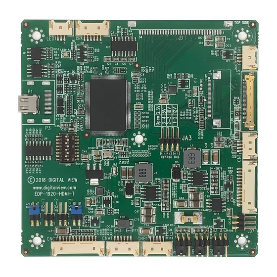
- Page 9 CONNECTORS, PINOUTS & JUMPERS The various connectors are: Summary: Connectors Purpose Description Audio output (Stereo) from Micro 12513WR-04 HDMI Serial control 12513WR-06 CNA1 Auxiliary power output 12513WR-06 CNB1 Backlight inverter 12513WR-06 CNC1 OSD controls 12513WR-12 Infra-Red sensor connector 12513WR-03 Micro HDMI signal input Micro HDMI LVDS panel signal FI-X30SSLA-HF...
- Page 10 Summary: Jumpers setting Purpose Note Panel power voltage select See panel voltage setting table 1 CAUTION: Incorrect setting will cause panel damage Backlight brightness voltage range 1-2 closed = 3.3V max 2-3 closed = 5V max Backlight inverter on/off control – signal level 1-2 = On/Off control signal „High‟...
- Page 11 DIP Switch selection – SW2 Pos #1 Pos #2 Pos #3 Pos.#4 Description Panel resolution For WUXGA panel Samsung LTM220CS01 1920x1200 AU Optronics B170UW02 V0 1920x1200 AU Optronics M215HW01 1920x1080 Samsung LTM230HT01 1920x1080 Samsung LTI400HA01 1920x1080 For UXGA panel NEC NL160120BC27-14 1600x1200 For WXGA panel Samsung LTA260W2-L01...
- Page 12 Pos #5 Pos #6 Pos #7 Description WUXGA UXGA SXGA WXGA SVGA VGA / WVGA Others SW1 Pos 8 = Reserved. DIP switch selection – SW1 Pos. # Function Description Panel pixel format OFF : Double Pixel ON : Single Pixel LVDS data mapping select ON : Mapping A (LVDS panel) OFF : Mapping B (LVDS panel)
- Page 13 CN1 – Audio output (Stereo) from Micro HDMI : YEONHO 12513WR-04 SYMBOL DESCRIPTION AMP L- Audio Left channel (Negative) AMP L+ Audio Left channel (Positive) AMP R- Audio Right channel (Negative) AMP R+ Audio Right (Positive) CN8 – RS-232 serial control: YEONHO 12513WR-06 SYMBOL DESCRIPTION SDATA...
- Page 14 J3 – LVDS output connector: JAE FI-X30SSL-HF SYMBOL DESCRIPTION VDD (+12V) +12V VDD (+12V) +12V VDD (+12V) +12V VDD (3,3V/5V) +3V3 / +5V (see JA3) VDD (3,3V/5V) +3V3 / +5V (see JA3) VDD (3,3V/5V) +3V3 / +5V (see JA3) TXB3+ LVDS Data 3+ TXB3- LVDS Data 3-...
-
Page 15: Controller Dimensions
CONTROLLER DIMENSIONS The maximum thickness of the controller is 4mm (measured from bottom of PCB to top of components) Any of the holes shown above can be used for mounting the PCB, they are 3.2mm in diameter. CAUTION: Ensure adequate insulation is provided for all areas of the PCB with special attention to high voltage parts such as the inverter. -
Page 16: Troubleshooting
TROUBLESHOOTING General A general guide to troubleshooting a flat panel display system it is worth considering the system as separate elements, such as: Controller (jumpers, PC settings) Panel (controller, cabling, connection, panel, PC settings) Backlight (inverter, cabling, backlight tubes) ... -
Page 17: Specifications
SPECIFICATIONS Panel compatibility 1920x1200, 1920x1080, 1680x1050, 1600x1200, 1400x1050, 1440x900, 1366x768, 1280x1024, 1280x800, 1280x768, 1024x768, 1024x600, 800x600, 800x480, 640x480, 480x640 resolution TFT LVDS LCD‟s support. No. of colours Up to 3 x 8 bit providing 16.7 million colours. Vertical refresh rate WUXGA, UXGA, WXGA, SXGA, XGA, SVGA, VGA resolution up to 60Hz. -
Page 18: Appendix I - Mode Support Table
Appendix I – Mode Support Table Micro HDMI (P1) port : Mode Resolution Horizontal Vertical [MHz] freq freq [Hz] [KHz] V_60 640x480 60Hz 25.175 31.469 59.940 SV_60 800x600 60Hz 40.000 37.879 60.317 X_60 1024x768 60Hz 65.000 48.363 60.004 SX_60 1280x1024 60Hz 63.81 60.020 UX_60... -
Page 19: Appendix Ii - Rs-232 Control Protocols
Appendix II – RS-232 control protocols RS-232 Serial control (Baud rate 2400, 8 bits, 1 stop bit and no parity) Physical connection : Controller side Computer side Connector interface : CN8 Connector interface : Serial port Mating connector : Molex 51021-0600 Mating connector : DB9 Female Mating face of CN8 Mating face of RS-232 DB9 Male... - Page 20 nn | “+” | “-“ | “r” | “00” – Continuous. timeout value/increment/decrement “R” | “?” Value – Round up to Reset Query nearest available step. If value > max available step, set it to the max available step. “0” “0” – Always On. “0”...
- Page 21 function when JB5 sets 3-4 closed * Apply for inverter control voltage in range of 0~5V. Each step interval is in 1 Backlight on “1” / off “0”. Backlight on/off 0xe1, Set backlight brightness = “0” | control Disable backlight “1”...
- Page 22 Other control Function Command Description Acknowledge (if enabled) 0xc1, “0” | “1” “0” – acknowledge Select RS-232 Disable/enable command acknowledge acknowledge. disabled. “1” – acknowledge enabled. “0” – not available. Command 0xc4, n Check whether a command “1” – available. availability is available.
-
Page 23: Appendix Iii - Appendix Iii - Ddc/Ci Support At Micro Hdmi Port
Appendix III – DDC/CI support at Micro HDMI port This controller (start from V1.07.00 or later firmware revision) supports the following DDC/CI commands at Micro HDMI port : Brightness Contrast RGB Color Input Source (Micro HDMI) Power States (On, Standby, Sleep) ... -
Page 24: Appendix Iv - Mapping Definition
Appendix IV – Mapping definition Definition of Mapping A : Page 24 of 28... - Page 25 Definition of Mapping B : Page 25 of 28...
-
Page 26: Appendix V - Dv Remote Control Unit Work For Dd-1920-Hdmi-T
Appendix V – DV remote control unit work for DD-1920-HDMI-T P/N 559000106-3 : DigitalView remote control unit (without DV logo silk screen printing) P/N 559000105-3 : DigitalView remote control unit (with DigitalView logo silk screen printing) BUTTON FUNCTION POWER BUTTON Soft power ON/OFF button. - Page 27 The manufacturer‟s liability for damages to customer or others resulting from the use of any product supplied hereunder shall in no event exceed the purchase price of said product. TRADEMARKS The following are trademarks of Digital View Ltd: Digital View ...
-
Page 28: Contact Details
Tel: (852) 2861 3615 Fax: (852) 2520 2987 Sales: hksales@digitalview.com WEBSITE www.digitalview.com Brand names belong to their respective owners. Specification subjects to change without notice. _________________________________________________________________________________________________________________ 1st issue: April 2016 (DD-1920 –HDMI-T– manual.doc) © Digital View Ltd 2016 Page 28 of 28...
Need help?
Do you have a question about the DD-1920-HDMI-T and is the answer not in the manual?
Questions and answers