Table of Contents
Advertisement
Quick Links
Preface
Thanks a lot for purchasing our ZTS-320(R) series total
station! As your handy construction toll, it will provide you
with the most efficient and economic solutions to your job. To
fully utilize the potential of your instrument and protect your
investment, you need to, as we strongly suggest, thoroughly
read this manual before starting any operations. Should you run
into any problem, Hi-Target‟s technical support team will be
happy to assist you.
Product insurance:In order to provide best service of our
company, please send back the instruments‟ version, number,
purchasing date and your valuable suggestions to us. Thank
you for your cooperation.
Notice: We reserve the rights of the updating of the
products and the improvement in the technical parameters
which we may not announce in advance. The Pictures in the
manual is for reference only, please take the actual item as the
standard.
1
Advertisement
Table of Contents

Related Manuals for Hi-Target ZTS-320R Series


Summary of Contents for Hi-Target ZTS-320R Series
- Page 1 Should you run into any problem, Hi-Target‟s technical support team will be happy to assist you. Product insurance:In order to provide best service of our company, please send back the instruments‟...
- Page 2 Features Abundant functions--- Our ZTS-320(R) series total station carry ample of survey applications and is capable of data storage, parameter settings and etc which suit all kinds of professional measurements. 1. Absolute coded disc is used to help an instant measurement without a calibration with reference points.
- Page 3 6. A laser plumb is adapted for convenient input of parameters of the stations set.
- Page 4 Notice: Avoid targeting sunlight with objective lens directly. Do not sight directly at the sun. Please install a sun filter to reduce the impact. Do not leave the instrument in extreme temperatures (too high or too low) or employ it when there is a dramatic difference in temperature.
- Page 5 The lens must be kept clean to improve accuracy of No-Prism measurement. When cleaning exposed optical devices, please gently wipe them with absorbent cotton or lens paper only. Any other material is inadequate. After a measurement, please purge away dusts from the instrument with flannelette or a hairbrush.
- Page 6 Security Guide Persons as well as prevention of property damage, be sure to read this manual for the safety of your product and prevention of injury to operators and other. Warnings: Total station fit out laser level 3R/IIIa which is recognized by the symbolsstuck above the “horizon-axis locking knob”...
- Page 7 Warnings: See directly into laser beams constantly is destructive. Precautions: Do not see directly into laser beams nor point laser to others. The reflection of laser beams received is essential signals of instrumental measurements. Warnings: Improper employment of Class 3R Laser instruments is destructive.
- Page 8 Precautions: On the basis of IEC Standard Publication 60825-1:2001, please ensure that every employer of our ETS-121series Total Station takes apt safety measures and precautions. Explanation of main part of the related IEC Standard Publication is as followed: Class 3R Laser Products are employed outdoors and on construction plants (for no-prism measurements).
- Page 9 g. Prevent that the laser accidentally rays surfaces such as plane mirrors, metals and windows, especially the plane mirrors and concave mirrors. * The injurious distance refers to the maximum distance between the source of the laser beams and the point where the laser beams decay enough to not harm human beings.
-
Page 10: Table Of Contents
Catalogue 1.Uses of Total Station .............. 15 2.Names and functions of the components ....... 17 2.1 Names of components ............17 2.2 Functions of keyboards and the display of information ..19 2.3 Functional keys under basic Measuring Mode ....25 2.3.1 Angle Mode(including 2 menu pages) ...... - Page 11 4. Preparations before measurements ........42 4.1 Drawing out and storing instruments ......... 42 4.2 Storage the instrument ............42 4.2.1 Using plumbs to centre and level (align) ..... 43 4.2.2 Using centering device to centre ......... 45 4.3 Unloading and charging batteries and information of battery conditions ..............
- Page 12 9.1.5 Surveying ..............84 9.1.6 Config of Surveying ............. 85 9.2 Staking out ................. 86 9.2.1 Staking out points ............87 9.2.2 Fast station ..............88 9.2.3 Resection method ............89 9.2.4 Equidistant stake-put ..........92 9.2.5 Entering coordinates ........... 93 9.3 File Management ...............
- Page 13 9.6.1 Adjusting index error(I.E) ........... 118 9.6.2 Calibrate TILT ............. 119 9.6.3 Add const&Mul. Const ..........121 9.6.4 Date and Time ............121 9.7 Grid Factor ................ 121 9.8 USART option ..............123 9.9 Selecting disc ..............123 10. Roadway ................124 10.1 Inputting Roadway ............
- Page 14 12. Technical parameters ............147 Appendix A: Explanation of file formats ........150 Appendix B Explanation of Protocol command ....... 151 Appendix C Explanation of format data ........153...
-
Page 15: Uses Of Total Station
1.Uses of Total Station A total station refers to such an instrument that measures azimuths and distances of targets and calculates the coordinates of targeted points automatically. It is fundamental in construction of national economy and defenses, as well as in building up of railways, motorways, bridges, irrigation, and programming and construction of cities. - Page 16 verticality, pipeline positioning, cross-section measurement etc. It also meets requirements for measuring trigonometrical-framework, relief(landform), cadastre and house property.
-
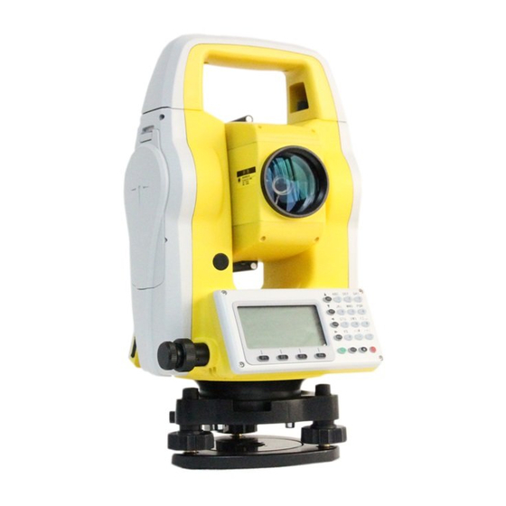
Page 17: Names And Functions Of The Components
2.Names and functions of the components 2.1 Names of components... -
Page 19: Functions Of Keyboards And The Display Of Information
2.2 Functions of keyboards and the display of information Symbols on the keyboard Symbol Name Function Enter Angle Mode Angle (can be also done by Measurement pressing the Up key under other modes or pages) Enter Distance Mode (can be also done by Distance DIST pressing the Down key... - Page 20 pressing the Left key under other modes or pages) Enter Menu Page (can be also done by pressing MENU Menu key the Right key under other modes and pages) Accept and save the inputs into the dialogue box and end the dialogue. Can be also used to open and close the right-angle Enter...
- Page 21 Enter numbers or Number keys characters or choose menu opts Enter symbols, Special Symbols decimals and signs Operate common functions of the instrument. Under pages of distance measurement, star key is for entrance of Star key ★ dialogue box for choosing opts.
- Page 22 Horizontal angle (clockwise increment). dHRis to stake out angle difference. Horizontal angle (anticlockwise increment) Horizontal distance. dHDisto stake out horizontal distance difference. Elevation difference. dVDisto stake out difference between elevation differences. Slope distance. dSD is to stake out differences between slope distances. North coordinate.
- Page 23 The magnitude of which deviates from the base line horizontally in a point projection measurement. Altitude of the target in a point projection measurement. Inter Feet International feet Us Feet American feet Maximum error of evaluated distance (used MdHD in resection measurement) Common reference functions of soft key Soft key Functions...
- Page 24 K.Pt Obtain coordinates of points from (Known) coordinate file Type in the name of the wanted point and Search search it in the current file to obtain coordinates. View List out details of the current record Displays the name, code and coordinate of Info.
-
Page 25: Functional Keys Under Basic Measuring Mode
2.3 Functional keys under basic Measuring Mode 2.3.1 Angle Mode(including 2 menu pages) Page Soft key Reference Function Save measured angle Save record into selected file. Set the horizontal Set0 angle to „0‟ Set evaluated horizontal angle with SetA keyboard which should not be greater than 360°... -
Page 26: Distance Mode(Including Two Menu
readout displayed on the screen would not change at all. Switch between HR (horizontal right/ clockwise) and HL (horizontal left/ anticlockwise) mode Vertical Angle Mode (altitude angle, Zenith, Horizontal „0‟, slope) Display the first page P2/2 for soft key functions. 2.3.2 Distance Mode(including two menu pages) Page Soft... - Page 27 measurement and save the measurement into selected files [measurement file„File(.MEA)‟ and coordinate file „File(.COO)‟are selected in operating menu or by star key) Meas Start Distance Mode Switch between four distance measurement mode [single accurate measurement Mode (sngl)/ repeated accurate measurement (rept)/ continue measurement (cont)/ tracking (track)] Display the second page...
-
Page 28: Coordinate Mode(Including Three Menu
2.3.3 Coordinate Mode(including three menu pages) Soft Page Reference Function Start coordinate measurement and save measurement into selected files [measurement Save file „File(.MEA)‟ or coordinate file „File(.COO)‟ are selected in operating menu or by star key] Meas Start coordinate measurement Switch between four distance measurement mode [single accurate measurement (sngl)/... - Page 29 measurement (cont)/ tracking (track)] Display the second page P1/3 for soft key functions Set target height and Setting instrument height Set coordinates of BBS (back-sight point) and back-sight angle Set coordinates for station Display the third page of P2/3 soft key functions Start offset measurement Offset (eccentric measurement)
-
Page 30: Explanation Of Saving Of Data
2.3.4 Explanation of Saving of data If you have never selected the measurement fileand it is your first time to use reference function of „Select file‟, then a dialogue box of „Select file‟ would appear to the screen. Mention that this is a good chance for you to select all files that the instrument may use. - Page 31 Settings led by star key(★) are as followed: Adjust contrast ratio by pressing „up‟ and „down‟ key(▲and▼). Adjust the lightness of backlight of the screen with „left‟ and „right‟ key (◀▶). Turn on or off backlight of the screen by pressing Key „F1‟.
- Page 32 automatically. If the calculated PPM value is not favored, please reenter your expected value.) Temp: 20.0℃ Press: 1013.0 hpa Prism c: 0.0 mm PPM: 0.0 ppm Signal: Clear Signal Enter Temp= Temperature Press= Atmospheric pressure Prism c= Prism constant PPM= PPM value B.S= Backspace Clear=clear up all typed in characters in the current column...
-
Page 33: Initial Setup
3. Initial Setup 3.1 On & Off Press and hold the „On/Off‟ key (and the buzzer buzzes once) until the screen displays pictures as below. The instrument is now switched on. (Picture for reference. Kind prevail) Now self-checking is accomplished and the instrumentautomatically enters Angle Mode (see details in 5. -
Page 34: Setup Of Skewed Calibration Of Horizontal And Vertical Angles
3.2 Setup of Skewed Calibration of horizontal and vertical angles When tilt (inclination) sensor is on, the instrument displays the automatic compensation to the horizontal angle caused by inclined plane. Concerning accuracy of angle measurement, please switch on inclination sensor wherever possible. -
Page 35: Setup Of Reflecting Prism Constants
3.4 Setup of Reflecting Prism Constants As a prism is selected as a reflector, a prism constant should be set before any measurement. If the constant is entered and set, it is saved and remains and will not be erased after switching off the instrument. -
Page 36: Setup Of Atmospheric Correction
3.6 Setup of Atmospheric Correction When measuring distances, the measured value can be influenced by the atmosphere. In order to reduce the influence, aatmospheric correction parameter is to be set. Temperature: the surrounding atmospheric temperature Atmospheric pressure: the surrounding atmospheric pressure PPM: calculated and predicted atmospheric correction The standard atmospheric value of ZTS-320(R) series... -
Page 37: Calculate Atmospheric Correction Out With Temperature And Pressure Sensor
3.6.2 Calculate Atmospheric Correction out with temperature and pressure sensor First, pre-measure the temperature and pressure of the surrounding at the measured station. e.g. Temp: +25℃ atm:1017.5 Press soft key „Enter‟ to move inserter to the „Temp‟ column and type in „25.0‟; Press soft key „Enter‟... -
Page 38: Setup Of The Minimum Readout Of Angles
D=S×[cosα+sinα×S×cosα(K-2) / 2Re] Measured Elevation after correction: H=S×[sinα+cosα×S×cosα(1-K) / 2Re] If not correcting Atmospheric Refraction and earth curvature, the formulae of our instrument for calculating horizontal distance and elevation are as followed: D=S×cosα H=S×sinα In the formulae: K=0.14-----------Atmospheric refraction constant (can be selected by practical) Re=6370 km---Radius of curvature of Earth α-----------------The vertical angle (counted from the... -
Page 39: Setup Of Addictive And Multiplying Constants
The setup of automatic shutdown on the instrument follows “MENU→5. options→9. Auto shut down. Opts displayed are as followed. Saving power >Never 5 minutes 10 minutes 20 minute Enter You may choose „Never‟ to set off auto shutdown. When choosing 5, 10, 20 minutes opts, the instrument will automatically shut down after chosen time if there is no key pressed. -
Page 40: Selecting Data File
in standardization site for baseline being measured by authenticated units). 3.11 Selecting Data File Data file acts as a database for following measurement or a storehouse for finished measurement. Please select a proper data file before all measurements. To select data file, see reference in 9. Operating Menu. Selecting data file on the instrument follows “MENU→1.Surveying→1.Select file”. - Page 41 LH= LS =Defined line File, working for staking out roadway Use ▲▼ keys to move indicator „>‟ to the wanted type of file and press „Enter‟ soft key to enter the File list as followed: A.MEA View Select Move the indicator to wanted file and press „ENT‟ or soft key „Enter‟...
-
Page 42: Preparations Before Measurements
4. Preparations before measurements 4.1 Drawing out and storing instruments Unpacking Lay down the tool box gently with top side facing up. Open the lock and unpack and draw out the instrument. Storage Mantle the telescope with its cover. Make sure that the vertical locking screw on the aiming component and the leveling bubble on the pedestal face upwards. -
Page 43: Using Plumbs To Centre And Level (Align)
4.2.1 Using plumbs to centre and level (align) 1) Set up the tripod ① Open the tripod. Make sure that the three feet of the tripod are approximately equal in distance from the center and that the top is leveled. Screw up the three locking screw. ②... - Page 44 4)Using tubular level to level the instrument precisely ① Screw off the horizontal locking screw and turn the instrument around to make the tubular level parallel to the line connecting any two adjacent A and B to move leveling bubble to the center.
-
Page 45: Using Centering Device To Centre
③Turn around the instrument by 90° again. Repeat the process in ○ 1 and ○ 2 until the bubble remains centered (leveled) at all sites. 4.2.2 Using centering device to centre 1) Set up the tripod ① Open the tripod. Make sure that the three feet of the tripod are approximately equal in distance from the center and that the top is leveled. -
Page 46: Unloading And Charging Batteries And Information Of Battery Conditions
Screw off the screw connection slightly and shift the instrument horizontally (mention that do not turn around the instrument about the vertical axis at all)according to the laser plumb the instrument aims at the station precisely. Each hand held one of two other unstamped feet of the tripod and adjust their position according to the plummet. - Page 47 battery is charged. For insurance concerns, please charge the battery in advance and prepare spare charged batteries. ② Different measurement modes consume charges with different rates. e.g. Displaying enough remainder of charges under angle mode does not make sure that these charges can support the instrument under distance mode at the same level (because distance mode consumes charges at higher rates).
- Page 48 Gently slide the battery on the charger slightly to make sure that it is finely positioned. Plug the charger into the outlet of 110V-220V AC power supply. Recharging begins. ▲The indicator light on the charger will illuminate three separate colors for various mode conditions: Solid Red Light—the charger is working;...
-
Page 49: Reflecting Prism
4.4 Reflecting Prism When measuring distance with prism selected as a reflector, a reflecting prism must be set at the target site. The reflecting prism can be connected onto the pedestal then onto the tripod with pedestal connection. It can be also positioned onto the centering rod. -
Page 50: Adjusting Eyepiece Lens Of The Telescope And Shacking On The Target
4.6 Adjusting eyepiece lens of the telescope and shacking on the target. How to aim at a target (only for reference) ① Aim at the bright sky with the telescope and adjust the eyepiece to focus until a sharp image of the cross wire forms; ②... - Page 51 The black box indicates that this column of information is selected and numbers and letters will be entered into this column only. The white slash in the box is the inserter. Press soft key „Num.‟ (F3) to switch between Numbers and Alphabet.
- Page 52 Press soft key „Alph.‟ (F3) to switch between letters and numbers. Press key „1‟ displaying „SUN1‟ in the column Switch to „Alph.‟again Press key „1‟ for once displaying „SUN1A‟ in the column Press soft key „Enter‟ to move inserter down to the STN column.
- Page 53 Notes: If information exists in the column already, the first number or letter you enter will clear up the column and be the first character of the column.
-
Page 54: Angle Mode
5. Angle Mode The instrument would enter Angle Mode automatically when starting. You may also enter this Mode by pressing „ANG‟ under basic measurement mode. Angle Mode involves two pages, being switched with soft key „F4‟. Their functions are explained as followed: On the first page Save: save measurement After pressing soft key „F1‟, dialogue box of „Information‟... - Page 55 Set 0: set horizontal angle to zero Press soft key „F2‟ The instrument displays: ENT→Set 0 ESC→Not Now press „ENT‟ to set 0 or „ESC‟ to quit. SetA: Set horizontal angle to desired degree Press soft key „F3‟ and the instrument enters page of „Set HA‟...
- Page 56 Turn around the aiming component and aim at the target, press soft key „F1‟ again and the horizontal angle is set at a new position. When the horizontal angle is hold, any key beside „Hold‟ will exert no effect on the instrument. L/R: Press soft key „F2‟, the horizontal angle column is switched between HR and HL modes.
-
Page 57: Distance Mode
6. Distance Mode Pressing key „DIST‟ may enter Distance Mode. There are two pages for Distance Mode, being switched by soft key „F4‟. The functions explanations are as followed: On the First Page: Save: save measurement After pressing soft key „F1‟, dialogue box of „Information‟ appears to the screen asking you to enter „Point name‟, „Code‟... - Page 58 Mode: used to select the working mode of the distance measuring device. Use keys ▲▼ to move the indicator „>‟ to the wanted opt. Press „ENT‟ to save setting. When selecting Rept (repeated), move indicator „>‟ to it and use keys ◀▶to choose the times for repeated measurement.
- Page 59 to enter „stake-out by distance‟ mode of Distance Measurement as followed. >dhd is to stake out horizontal distance difference. A positive result indicates that the measured horizontal distance is greater than the evaluated one. The lens should be shifted to the instrument.
- Page 60 ” indicates that the distance measurement Notes:“ is under operation. Now pressing „F1‟ or „F2‟ appears “ ” or “ ” on the screen, which indicates that the distance measurement is under operation and displays the current measuring mode (S, R, C, T). When quitting distance measurement with „ESC‟, the “...
-
Page 61: Coordinate Mode
7. Coordinate Mode Presskey „CORD‟ to enter Coordinate Mode. According to the diagram below, please set up the coordinate of the station, azimuth angle, target height and instrument height before coordinate measurement. Coordinate measurement diagram There are three pages for coordinate mode, being switched with soft key „F4‟. - Page 62 to the previous point name. The code entered depends on your requirements and the target height depends on facts. Press „ENT‟ to save measurement. P.S. If having not selected file at first when pressing „Save‟ under Angle Mode, a dialogue box of „Select File‟...
- Page 63 Height of Ins.&Target Clear Save Enter After finishing entering, press „ENT‟ or soft key „Save‟ to save the setting. However the setting will be erased when shutting off if using „ENT‟ to save; inversely, using soft key „Save‟ will remain the setting forever providing that there is no change of the setting.
- Page 64 Setting up BBS is to relatethe coordinate of earth stationto the coordinate of the instrument (being used together with STA Function). After setting the BBS and pressing „ENT‟, the instrument asks users to aim at the BS (target point). After pressing „ENT‟ to orient, the instrument will calculate the azimuth angle of the BBS, which is displayed in the HA (horizontal angle) column.
- Page 65 (A.COO)1/ COO: COO: Search Begin View Select the points with the help of keys ▲▼ and press „ENT‟ to save the your choice. If cannot get the point, the coordinate will remain its origin and the instrument will display „Can‟t be get!‟. Press „M.Pt‟...
- Page 66 Press soft key„F1‟ to operate offset function. Offset function is designed to obtain coordinate information of the measured point when prism cannot be place at the measured point or when distance measuring cannot be done. Offset function is divided into Angle Offset, Single/ Double- distance Offset, Plane Offset and Column Offset.
-
Page 67: Offset Mode
8. Offset Mode Offset function is designed to obtain coordinate information of the measured point when prism cannot be place at the measured point or when distance measuring cannot be done, being divided into Angle Offset, Single/ Double- distance Offset, Plane Offset and Column Offset. The functions are included in the „Offset‟... -
Page 68: Angle Offset Mode
8.1 Angle Offset Mode It is specifically adequate when facing difficulties setting up prism. E.g. in the center of a tree. Set up the prism at point P which is the same horizontal distance away from the instrument as A0 is from the that. The diagram for angle offset is as followed. - Page 69 The target height (H.T) indicates the point where prism is placed. You may use soft key „T.H‟ to re-set target height before measurement if needed. Press „Meas‟ to start measurement. After measurement, press ‟ENT‟ to enter „Offset (Angle)-Result‟: the offset points here indicate A0 or A1 on the working path.
-
Page 70: Single-Distance Offset Mode
Now turn around the aiming component to aim at the offset point. The coordinate of the point is obtained and press soft key „Next P‟ to enter the offset measurement of the next point; press soft key „Record‟ to save the coordinate of the offset point. Finally, press key „ESC‟... - Page 71 Enter „2. Offset (Dist 1)‟ from the offset menu. Seemeanings of „+‟ and „-‟ in the diagram of single-distance offset. After entering the known offset distance, press „ENT‟ to save the setting and enter „Offset (Dist 1)—point‟...
-
Page 72: Double-Distance Offset Mode
Press „Meas‟ to start measurement. After measurement, press ‟ENT‟ to enter „Offset(Dist1)-result‟. The coordinate of the point is obtained and press soft key „Next P‟ to enter the offset measurement of the next point; press soft key „Record‟ to save the coordinate of the offset point. Finally, press key „ESC‟... -
Page 73: Plane Offset Mode
Firstly, enter the offset distance (OSD). If the directions of P1-A0 and P0-P1 are the same then the distance is positive, otherwise it is negative. Press „ENT‟ or soft key „Enter‟ to save setting and enter page of „Offset(dist2)-begin‟. To measure the point, you must aim at P0 as shown above. - Page 74 Mention that the target height under this mode must be 0 Enter „4. Offset (Plane)‟ from the offset menu Press soft key ‟Meas‟ to measure the first point P1 After measurement, press „ENT‟ to accept the result. Mention that the target height is set to be 0 automatically. After pressing „ENT‟, users enter „Offset (plane)—Pt.2‟.
-
Page 75: Column Offset Mode
Now turn around the aiming component of the instrument to aim at the offset point. Mention that the offset point must be on the defined plane but not below the prism bar for concerns of precision. The coordinate of the offset point is obtained. Press soft key „Next P‟... - Page 76 Enter „5.Offset(column)‟ from the offset menu. If coordinate of P0 is wanted, please set target height to be 0 before measurement. If coordinate of P0‟ is wanted, please set target height depending on facts. Then press „Meas‟ to start measurement. Press „ENT‟...
- Page 77 Aim at the left edgeand press soft key „Enter‟ Enter „Offset(column)—Right edge‟. Aim at the right edge and press soft key „Enter‟ Enter „Offset(column)—Center‟ which displays the result of Offset(column) measurement. Now press soft key „Next P‟ to enter the offset measurement of the next point;...
-
Page 78: Operating Menu
9. Operating Menu Notes: all diagrams of menu under section 9does not fully display the options. Kind prevail. Pressing „MENU‟ under basic measurement mode appears a page as followed on the screen: The useful keys under menu page are: ▲ Shift upwards by one column ▼... -
Page 79: Surveying
9.1 Surveying Surveying includes functions as followed: Surveying 1.Select file 2.Station 3.Orientation(BBS) 4.Orientation(SetA) 5.Surveying 6.Config of Surveying 9.1.1 Select files The function „Surveying‟ includes a sum of all preparation work before a survey. A measurement file for storage of measurement result and record, a coordinate file for accessing known points and a code file for fast checking codes must be selected before any measurement. - Page 80 MEA= Measurement File, working for storing data COO= Coordinate File, being used when transferring coordinate COD= Code File, being used when transferring code LH= LS= Defined line File, working for staking out roadway Use ▲▼ keys to move indicator „>‟ to the wanted type of file and press „Enter‟...
-
Page 81: Setup Of Stations
9.1.2 Setup of stations The dialogue box followed included all needed information to be entered of a station. With keyboards or transferring coordinate from K.Pt (Known points) and M.Pt (Measured points), users may input the coordinate of a station. Press „Input‟(soft key F1) to enter the coordinate of a station manually. -
Page 82: Setup Of Bbs(Back-Sight Point)
Select the points with the help of keys ▲▼ and press „ENT‟ to save the your choice. If cannot get the point, the coordinate will remain its origin and the instrument will display „Can‟t be get!‟. Press „M.Pt‟ (Soft key F3). The operation is the same as that of „K.Pt‟... -
Page 83: Setup Of Azimuth
DHR: DHD: Meas Mode Coord Save After the measurement, the instrument displays the difference between theoretic distance and the measured distance. Press soft key F3 „Coord.‟ to display the coordinate of the measured current BBS. You may compare it with the entered value. -
Page 84: Surveying
9.1.5 Surveying T.H: Pt.name Offset Save Reco If have set the instrument to „survey first‟how to set→, after pressing soft key F4 „EDM‟, the instrument then start measurement of the coordinates. As soon as the measurement is done successfully, the soft key „record‟appears. Press „Record‟ to enter page of „information‟. -
Page 85: Config Of Surveying
9.1.6 Config of Surveying Use ◀▶ to select Sequence Users may choose to „survey first‟ or to „edit first‟ when undertaking measurement under surveying mode. Same point Users may choose to check or not to check if there is a duplicate of name in the list. -
Page 86: Staking Out
9.2 Staking out Staking out is to find the earth point needed when designing. The common process to stake out is as followed: 1. Select a file for staking out to access to and transfer coordinate of STA and BBS and data of staking-out point etc. 2. -
Page 87: Staking Out Points
9.2.1 Staking out points Stake out XX point Stake out:XX M.Pt K.Pt Enter The coordinate point can be defined manually with keyboard entering. It can be also defined by transferring coordinates from Measured points or Known points, which requires you to select a file in advance for transferring coordinates, otherwise the system will go to page for selecting file automatically. -
Page 88: Fast Station
dHR: a negative value indicates a clockwise rotation of aiming component. Inversely, positive value indicates a anticlockwise rotation. dHD: a positive value indicates that the lens should shift to the instrument. Inversely, a negative value indicates that it should shift away. dN: a negative value indicates that the lens can reach to evaluated staking out point if moving north. -
Page 89: Resection Method
90°12′22″ 200°54′12″ -10.756 -0.004 Mode Meas Press „Meas‟ to measure the coordinate of the new control station. Save it into proper file in relation to demand for concerns of transferring later on. „Sequence‟, „same point‟ and „edit point‟ functions under „Config of survey‟ is valid here as well. - Page 90 Resection-No.1 Vz: 77°18′30″ HR: 180°34′55″ HD: 4.978 T.H: 1.000 Mode Angle Dist Choose angle or distance to undertake resection. If choosing angle mode then the instrument will start measuring distance. After a successful measurement, the system will display „Next P‟ Press soft key „Next P‟.
- Page 91 Resection-No.1 0.002 -0.003 0.000 Result Cord Now press soft key „F1‟ to setup station and record. After setting up station, users may find that the station name becomes „RESSTA‟ and the coordinate is the resection one. Press „F4‟ to switch between „Coord.‟ and „dCoord.‟ (difference between coordinates).
-
Page 92: Equidistant Stake-Put
9.2.4 Equidistant stake-put Sometimes users may need to stake out N points on a line uniformly. An equidistant stake-out is adequate in doing such work. When undertaking equidistant stake-put, users may first measure the coordinate of the origin/begin (prism P0) then that of the terminal/end (prism P1). -
Page 93: Entering Coordinates
The „stakes‟ must be set while the space can left blank. If setting the stakes to be 12 with space left blank, then the middle points can be staked out uniformly during the following equidistant stake-out. Space is the number of points staked out uniformly from the begin to the end. -
Page 94: File Management
Using keys „◀▶‟ helps to scan the sequence of each point. e.g„1‟ indicates the number of the point when it is recorded or scanned. After setting up one record, press „ENT‟ to accept the setting and enter the setting page of the next record. If do not need record any more, press „ESC‟... -
Page 95: File Dialogue Box
9.3.1 File dialogue box Each file involves operations of „establish new files‟ (New), „delete files‟ (Del) and „view‟(View) which is called File management here. After choosing a file, users may enter file list which displays the names of the file. All files obeys the same rules of operations. - Page 96 Select: Press soft key „Select‟ to select the current working file of the instrument. You may select your file repeatedly and the selection can be checked in the „Select file‟ dialogue box. MEA= Measurement File, working for storing data COO= Coordinate File, being used when transferring coordinate COD= Code File, being used when transferring code LS= LH =Defined line File, working for staking out...
-
Page 97: Import
instrument will not warn you for duplicated name when not establishing a new same file. Del: delete the file the indicator column indicates. Box of „Delete will lose data‟ appears on the screen when pressing soft key „Del‟. Press „ESC‟ to quit or „ENT‟ to delete. View: when pressing soft key „View‟... - Page 98 importing code files, users must select files with suffix „.COD‟ and import .COD files into PC machine. Importing from PC Press the "MENU" button to enter the menu screen, select "Import file" option, enter the interface of file import, select the "Import from PC"...
- Page 99 codes and defined line files will refresh all records automatically. Import from USB The form of imported file which from U disk must be a text file and only it be saved in the "ts_prj \ import" directory of the U disk , can it be identified. The format of the text file is "PT, E, N, Z, CODE".
-
Page 100: Export
coordinates which you want to import (there you can create a new file) such as SVY.COO, then the interface is shown below: Press the "Import " button, the coordinates data in“0712.txt”will be imported to the SVY.COO file of Total Station, then you can view the data in the menu of maintenance file. - Page 101 The only files able to be exported are the measurement files. See references of the soft keys in 9.3.2 The connected computer may be set ready to receive files when exporting without special operations. The exported file will be in the format of ASCII. See explanations for forms in Appendix B.
-
Page 102: Format Disk
9.3.4 Format disk After entering „4.Format disk‟, a box of „Warning! Formatting will lose data. Export data first.‟ will appear on the screen. Press „ENT‟ to continue formatting, otherwise „ESC‟ to quit. After formatting, all record in the instrument will disappear. - Page 103 2. Connect the instrument to the computer through serial port connector. Open the hyper terminal softwareand set up the correct port. Then set „Bits per second‟ to 115200 and „Flow control‟ to „None‟. Finally, when all operations above are done, press „ENT‟...
- Page 104 4. Press key „1‟ on the instrument. The instrument enters wait state for sending programs. After the state, click„Send File…‟ on the computer. 5. Select the new version of total station software and click „Send‟ on the computer.
-
Page 105: The Instrument As A Memory Disc
6. Then the computer displays the process of sending. After finishing updating, please close the hyper terminal. Before starting and operating the instrument, please first unload the battery of it and then load it with battery again. The instrument is successfully pdated now. 9.3.8 The instrument as a memory disc Users may use Mini USB connector to connect the instrument to PC machine. -
Page 106: Programs
9.4 Programs 9.4.1 Remote height (REM) REM is adequate for measuring target height when the prism cannot be placed at the target point. Under REM mode, users may place the prism on any point along the plumb line of the target point to obtain target height. There are two modes for REM measurement: „with TH‟... - Page 107 3.Aim at the prism and press soft key „Meas‟ to obtain the horizontal distance of the target from the instrument. Press soft key „Enter‟ to enter „REM-Ground to target‟ 4.Then, turn the telescope up and down to aim at the target point.
- Page 108 1. The system goes to „REM-prism‟ page directly. 2.Aim at the prism and press soft key „Meas‟ to measure the horizontal distance of the prism from the instrument. Press soft key „Enter‟ to enter „REM-Base‟. 3. Aim at the reference point and press „Select‟ to enter „REM-Altitude‟...
-
Page 109: Mlm
4. Then turning the telescope up and down. The elevation difference between the target and the reference point is displayed in the VD column. 5. After the measurement, users may choose from three opts: „Set VA‟ to re-enter the „REM-Altitude‟ page. „HDist‟... - Page 110 You may also have to choose „Considering Grid scale‟ or to „Ignore Grid scale‟ before choosing measurement mode. MLM (A-B, A-C) 1. Enter the „MLM(A-B,A-C)-Step 1‟ page MLM(A-B,A-C)-Step1 69°12′13″ 170°12′21 4.358 Meas Coord Mode 2.You may measure the coordinate of the starting point out by pressing soft key „Meas‟...
-
Page 111: Polar Coord. Measurement
MLM(A-B,A-C)-Result dSD: -3.852 dHD: -3.836 dVD: 0.344 90°30′35″ Next P 4. Display the result of MLM measurement. Press soft key „Next P.‟ to continue MLM Measurement, repeating the „Step-2‟ and „Result‟ pages. The measuring process under MLM(A-C,B-C) is all the same as that of MLM(A-B,A-C). -
Page 112: Coord.z
4. Following the prompt on the screen, aim at the BS. As soon as pressing „ENT‟ to finish setting up station, the instrument will undertake a measurement automatically. Horizontal Angle is set 0 and one marginal datum is saved. 5. After setting up station, users may stimulate process in surveying to survey polar coordinates. - Page 113 2. Enter „Coord.Z-No.1‟ page Coord.Z-No.1 Pt.name Code: [★] Select file Input K.Pt Info M.Pt To define Coord.Z-No.1, follow the process of defining BBS. Press „ENT‟ to confirm and end the dialogue, entering „Coord.Z-No.1‟ measurement page. Coord.Z-No.1 Meas Mode Enter 3. Press soft key „Meas‟ to start measurement. After the measurement, the „HR‟‟SD‟‟VD‟are displayed on the each column.
-
Page 114: Area
Coord.Z-Resul BSA: 170°12′23″ 1.234 0.001 SetZ Then users may use „SetZ‟ to set the z coordinate of the station. You may also use soft key „Set A‟ to set the BBS of the instrument. Press „ESC‟ to quit coordinate measurement. 9.4.5 Area This function is to help calculate the area of the plane figure formed by measured and inputted coordinates out. - Page 115 The inputted and measured coordinate is inserted below the indicator column, which determine the shape of the formed area. 3.The area enclosed is the connection of line from the begin to the end (begin) one by one in order. Thus, the instrument may not get the correct area of which has intersection on the half way.
-
Page 116: Projection
9.4.6 Projection The function serves to measure the length (X), distance (Y) and altitude difference (Z) the prism deviates from the baseline origin and the baseline. The preparation work before measurement is: setting up instrument height, target height and defining the baseline. Setup baseline: Press soft key „Meas‟... -
Page 117: Roadway
The soft key „T.H‟ serves to reset the target height. The soft key „Mode‟ serves to switch between displaying „rN, rE, rZ‟ and displaying „SD, HD, VD‟ of the measured point from the baseline projection point. 9.4.7 Roadway See reference in 10. Roadway 9.5 Options Config 1.Units... -
Page 118: Calibrate &Config
Use keys▲▼to move the indicator „>‟ up and down to the wanted opt. Press soft key „Enter‟ to confirm your choice. The instrument will display box of „saved‟ and the setting remains even after shutting down. Afterwards, the default EDM mode of the instrument will be that of your choice until next time you change the setting. -
Page 119: Calibrate Tilt
steps, the instrument will then calculate the index error and display it. Now press „ENT‟ to save the index error (calibration done), otherwise press „ESC‟ to quit (previous I.E remains). 9.6.2 Calibrate TILT When calibrating tilt, please make sure that the tilt is off and the index error is little. - Page 120 2. Set the vertical angle to V0+3′with the help of the vertical inching screw. Adjust the screw C to aim at the target precisely. Press „ENT‟ to confirm after a stable readout appears. 3. Set the vertical angle to V0-3′with the help of the vertical inching screw.
-
Page 121: Add Const&Mul. Const
Notes: Co.k (linear coefficient) must be less than 1.5; Co.Z (zero position) is normally between -20 and +20, otherwise the compensator(tilt) must be adjusted mechanically. 9.6.3 Add const&Mul. Const The addictive constant and the multiplying constant can be adjusted after strict measurement. We suggest you to employ professional and authenticated factories or units to measure and set these constants. - Page 122 Formulae: 1) Altitude factor= R/(R+Altitude) R= average earth curvature radius Altitude: The altitude above average sea level 2) Scale factor= The scale factor on the station 3) Grid scale factor = Altitude factor× Scale factor Distance measuring: 1)Grid scale distance(HDg)= HD× Grid scale factor HD= distance on the ground 2) Distance on the ground(HD)= HDg/Grid scale factor Gird scale...
-
Page 123: Usart Option
9.8 USART option RS232C means that when two-way communication, the system will export and import through the RS232C port. Bluetooth means that when two-way communication, the system will export and import via blue tooth. 9.9 Selecting disc FLASH means that the working files and coordinate files will be saved into the internal storage. -
Page 124: Roadway
10. Roadway To open roadway program, follows „Menu→4.Prog.→7. Roadway‟ Roadway function is divided into two parts: Design Roadway and Stake-out Roadway. Users may stake out designed points according to the mileage and deviation of the Designed Roadway. You may practice with roadway function with the assistance of Appendix A. -
Page 125: Inputting Roadway
10.1 Inputting Roadway Roadway design requires input of horizontal lining and vertical lining. The input will be saved to LS files. The maximum number for elements is 21 in each file and the number of intersection cannot be greater than 7. 10.1.1 Horizontal lining An input for roadway design. - Page 126 Define(H)-Begin Mileage: Enter Clear You may then define horizontal lining with „Line‟, „Circle‟ or „Spiral‟ alternately. Note: Do not define the length as „0--0‟, which serves for ending lining. Input „line‟: Define(H)-Line Radius: Length: Clear Enter Input „Circle‟: Define(H)-Circle Radius: Length: Clear Enter...
- Page 127 The input of Radius can be negative. The positive direction is the right direction along the designed roadway, and the left is negative. The length refers to Arc length. Input „Spiral‟ Define(H)-Spira Radius: Length: Clear Enter The radius and length here is the same as those in „Define (H)- Circle‟...
- Page 128 List of curve 01st: 7.000 02st: 7.000 02st: 10118.000 Save View Now press soft key „save‟ to save and quit the box. If choosing to „view‟, the system lists out the information of the inputted element. e.g. Define(H)-Spiral Radius: 255.000 Length: 100.000 Edit PgUp...
- Page 129 N: (Pt.1) E:……………… Radius: Enter Clear The column „Pt.1‟ is in relation to your inputted intersection number. The system will not accept negative Para. A1, Para. A2 nor Radius R. If inputting the radius, then the system will insert arc with defined radius in between the former point and the next point.
- Page 130 [Notes*]: When inputting A1 and A2 according to the length of the spiral L1 and L2, the formulae to calculate A1 and A2 are as followed: A1=√(L1·Radius) A2=√(L2·Radius) Press „ENT‟ to input the next intersection now. If N, E coordinates and radius are not entered at all, there will be no response from the instrument.
-
Page 131: Vertical Lining
10.1.2 Vertical Lining Vertical lining is formed by a group of intersection points. The intersection points possess mileage, altitude and curve length. The curve length of beginning and ending point of Vertical lining must be 0. The number of intersection points of vertical lining can be 12 maximum. -
Page 132: Staking Outroadway
Enter the mileage, altitude and length one by one and press „ESC‟ to end the input and go to „List of V curve‟. The uses of „Save‟, „View‟ and „Edit‟→ You may continue inputting V curve through „5.Resume V curve‟. After finishing defining H and V curve, the last input will be saved in the buffer storage cache and will be erased when shutting the instrument down. -
Page 133: Selecting Roadway File
The steps for staking out road way is as followed: 1. Select [.LS] files for stake-out 2. Setup station 3. Setup BBS 4. Inputting Roadway parameters, including mileage of begin (start mileage), space between, left and right deviation (Left/Right dist) and left and right altitude difference (Left/Right dV) 5. -
Page 134: Setting Stations And Bbs (Back-Sight Points)
Both ways above lead to page of „select file‟. Shift indicator > down to the opt „File (.LH)‟ and press soft key „Enter‟. The system will list out the available [.LS] files. After selecting file, press „ENT‟ to load the buffer storage cache with the selected [.LS] file. - Page 135 Press „Stake‟ under this page: Pt.name: Code: Record Enter Point name indicates the mileage of the selected stake. The system accepts maximum 8 characters of the point name. You may now press „Record‟ to save the point to be staked out to the current coordinate file, otherwise, press „ENT‟...
-
Page 136: Adjustments And Corrections
11. Adjustments and Corrections The ZTS -320(R) total station are all calibrated and checked before entering the market. However, it is inevitable that long distance transportation or environmental change alter the parameters of the optical components. Thus, for concerns of precision, please check and calibrate your instrument before any measurement. -
Page 137: Circular Level
11.2 Circular Level Check If the bubble of the circular level is centralized after adjusting the tubular level, then it is not necessary to adjust the circular one again. Calibration If the bubble is not centralized, adjust the correction screws under the bubble with a correction needle or a hexagon spanner until it is centralized. - Page 138 (as shown on the left below), otherwise a calibration is necessary (as shown on the right below). Calibration 1. Unload the reticule cover between the eyepiece and the focusing knob. Now you see three fixing screws of the reticule 2. Screw off three fixing screws (see picture below) uniformly with a screwdriver.
-
Page 139: Perpendicularity Of Collimation Axis And Cross Axis (2C)
11.4 Perpendicularity of Collimation axis and Cross axis (2C) Check 1. Set target A to be about 100 meters away from the instrument and set the vertical angle of the target to be within ± 3° . Level the instrument precisely and turn on the instrument. -
Page 140: Tilt Compensator
4. Screw up the correction screw and cover the reticule. Note: Mention that users have to check the depth of parallelism between Collimation axis Electro-optic Emission axis 11.5 Tilt compensator Check 1. After placing and leveling the instrument, align laser beams and the line of connection between the instrument center and any leveling screw on the bottom of the instrument. -
Page 141: Vertical Index Error (Angle I) And Set Vertical Index 0
instrument is over 3′, which is over the range the instrument was designed to compensate. Screw the leveling screw back towards the opposite direction, the vertical angle re-appears on the screen. It shows that the tilt works well now. Users may observe the change of the readout about the critical point. -
Page 142: Centering Device
Note: 1. Repeat the checking process to re-measure the index error (angle i). If the index error still does not requirement, a checking of the three steps of calibration ofset 0 for index is to be undertaken. It is highly possible that errors are made in the three steps.e.gwhther it was precise when aiming at the target. -
Page 143: Addictive Constant(K)
Calibration 1. Unload the cover of the laser plumb and adjust the three correction screw with 1# hexagon spanner to adjust the three screw. Obey the rule to screw off one side and screw up the other. Finally adjust the laser plumb spot to point 0 (origin). 2. - Page 144 K should approach to 0. If the absolute value of K is greater than 5 mm, then users may have to set the instrument in a standardized baseline field for strict measurement. Calibration If proving that the constant K changes and does not approach to 0 after a strict checking, then adjust the constant by setting the addictive constant as a integrated constant K.
-
Page 145: Depth Of Parallelism Between Collimation Axis Electro-Optic Emission Axis
11.9 Depth of parallelism between Collimation axis Electro-optic Emission axis Check 1. Place a reflector prism 50 meters away from the instrument 2. Aim at the reflector prism center precisely with the cross wire of the telescope 3. Observe the maximum signal through starkey(★)→Para.→Signal, and find the center of the electro-optic emission axis. - Page 146 Please first check the coaxality of the laser beam that if the laser beams deviates, otherwise the measurement can be inaccurate. Warnings: Do not look into laser beams directly! Do not aim at others with laser beams! Check Face the grey side of the provided reflector to the instrument, being about 5 and 20 meters away.
-
Page 147: Technical Parameters
12. Technical parameters Serial ZTS-320(R) Anglemeasuring (Hz, V) Theory used Absolute code disk 1″ Min angle readout 2″ Precision Telescope Magnification 1°30′ Field angle Min sight distance 1.5m Cross wire Lighting Tilt compensator Integrated liquid System single-axis compensator Working range ±... - Page 148 repeated/tracking) No-prism distance measuring Ranging with white target 350m (short distance no plate prism measurement) >7500m Ranging with single prism Precision (short 3mm± 2ppm distance/tracking/prism) Measuring time (short 2~6 s distance/tracking/prism) Communication Memory capacity 20000 points Port Standard RS232 serial port Data format ASCII Operation...
- Page 149 Storing temperature -40℃~+70℃ Water proof & dust proof (according to standard IP54 IEC60529) Weight Include battery and pedestal 5.5kg Battery Type High-energy lithium battery Voltage/ capacitance 7.4 V; 3000 mAh 16 hours (under 25 ℃ with a fully charged battery, measuring once for every thirty Working duration minutes)
-
Page 150: Appendix A: Explanation Of File Formats
Appendix A: Explanation of file formats Explanation of formats of files: ST001, 1.2050, AD 100.0000, 100.0000, 10.0000 BS001, 1.8000, BA 200.0000, 200.0000, 10.0000 A1, 1.8000, CODE1 104.6625, 99.5679, 10.2148 A2, 1.8000, CODE1 1276939, 288678, 4.7510 A3, 1.8000, CODE1 1276942, 288678 Every record consists of two lines: line records the record type, point name, target height, code... -
Page 151: Appendix B Explanation Of Protocol Command
Appendix B Explanation of Protocol command Another device can operate Total station through RS232 or Bluetooth using the commands as follow: "\006006",0-- command correct response "\021021",1-- command incorrect response "C067\003",2-- measure and return the data "N078\003",3-- stop measuring "ZA0043\003",4—direct to close "ZA1067\003",5-- direct to open "Z10091\003",6--H/V "Z12089\003",7--HR... - Page 152 "Z54091\003",23—VD accurate measurement "Z55090\003",24—VD repeat accurate measurement "Z61093\003",25—NE tracking measurement "Z62094\003",26—NE loose measurement "Z63095\003",27—NE repeat loose measurement "Z64088\003",28—NE accurate measurement "Z65089\003",29—NE repeat accurate measurement "Z71092\003",30—NE tracking measurement "Z72095\003",31—NE loose measurement "Z73094\003",32—NE repeat loose measurement "Z74089\003",33—NE accurate measurement "Z75088\003",34—NE repeat accurate measurement "Z81083\003",35—Z tracking measurement "Z82080\003",36—Z...
-
Page 153: Appendix C Explanation Of Format Data
Appendix C Explanation of format data Total station will transmit measured data to extern device after receiving commands from the extern device. 1) SD mode (ID: 3FH) : „?‟ indicates slope distance (ASCII 3FH) Slope distance 1178.481m (+/-, 8 digits) meter/feet Vertical angle 85'20'30"... - Page 154 3) N or E or Z coordinates mode N : N (X) coordinate -596.337m 8 digits) E : E (Y) coordinate +1011.930m 8 digits) Z : Z coordinate +95.802m (+/-, 8 digits)
Need help?
Do you have a question about the ZTS-320R Series and is the answer not in the manual?
Questions and answers