Table of Contents
Advertisement
Preface
Thank you for purchasing our ZTS-320 series total station!
This manual is your good helper, please read it before operate
the instrument and keep it properly.
Product Validation
In order to get our best service, please give the feedback
about the version, number and purchasing date of the instrument
and your valuable suggestions to us after you purchase our
product.
We will attach great importance to every piece of advice
from you!
We will pay much attention to every detail of our products!
We will make great efforts to provide better quality!
Notice: We reserve the right to change the technical
parameters during updating and improving our products and we
may not announce you in advance. The Pictures in this manual is
for reference only, please in kind prevail.
1
Advertisement
Table of Contents

Related Manuals for Hi-Target ZTS-320 Series


Summary of Contents for Hi-Target ZTS-320 Series
- Page 1 Preface Thank you for purchasing our ZTS-320 series total station! This manual is your good helper, please read it before operate the instrument and keep it properly. Product Validation In order to get our best service, please give the feedback...
- Page 2 Features Rich Features--- Our ZTS-320series total station carries abundant surveying applications ,at the same time has the functions of data storage, parameter settings and etc .It‟s suitable for all kinds of professional measurements. 1. Absolute code disc Equipped with absolute code disc , the instrument can measure after switched on .Even if reset the battery halfway, the azimuth information will not be lost.
- Page 3 Notice: Do not look directly into the sun with instrument. Do not leave the instrument in extreme temperatures (too high or too low) or use it when temperature shock. The instrument when not in use, should be loaded in the box , placed in well-ventilate and dry place ,and pay attention to the shockproof ,dustproof and damp-proof.
- Page 4 Security Guide Please pay attention to the following security matters when using the instrument with non-prism. Warnings: Total station is equipped with rangefinders with laser level 3R/IIIa ,which is recognized by the following logo recognition at the horizon-axis locking knob” of the instrument, saying “Class 3A Laser Product”.
- Page 5 Class 3R Laser Products are used in outdoors and on building site (with non-prism measurements). The personnel who is specially trained, qualified and authenticated are allowed to stall, adjust and operate these laser instruments. b. Set up corresponding laser warning signs in the use of area range.
-
Page 6: Table Of Contents
Catalogue 1.Uses of Total Station ..............9 2.Names and functions of the components ......... 10 2.1 Names of components ............. 10 2.2 Functions of keyboards and the display of information ... 12 2.3 Functional keys under the basic measuring mode ....15 2.3.1 Angle Mode(including 2 menu pages) ...... - Page 7 8.5 Column Offset Mode ............... 47 9. Operating Menu ................ 49 9.1 Surveying ................. 49 9.1.1 Select files ................50 9.1.2 Setup station ..............50 9.1.3 Setup BBS(backsight point)..........51 9.1.4 Set azimuth ................ 52 9.1.5 Surveying ................52 9.1.6 Config of Surveying ............53 9.2 Staking out ................
- Page 8 10.2.1 Selecting Roadway File ........... 83 10.2.2 Setting stations and BBS (back-sight points) ....83 10.2.3 Staking out Roadway............83 11. Adjustments and Corrections ..........85 11.1 Tubular Level ................85 11.2 Circular Level ................85 11.3 Reticule of the telescope ............86 11.4 The Perpendicularity of Collimation axis and Cross axis (2C).
-
Page 9: Uses Of Total Station
The ZTS-320 series total station is equipped with absolute code dial system, integrated-circuit-control-board ranging item and microcomputer for measurements of angle and distance and for calculation, display, depositing and etc. -
Page 10: Names And Functions Of The Components
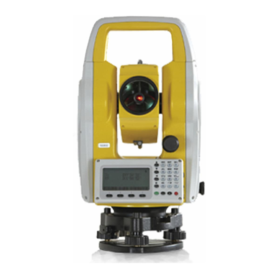
2.Names and functions of the components 2.1 Names of components Handle Objective lens Horizontal axis center Coarse sighting device Display Horizontal locking knob keys Horizontal slow motion knob Base... - Page 11 Handle Handle knob Coarse sighting device Focusing knob eyepiece Vertical clamping screw number Vertical tangent screw SD card port serial port connector Mini USB port (On the other side) Leveling screw Base...
-
Page 12: Functions Of Keyboards And The Display Of Information
2.2 Functions of keyboards and the display of information Symbols on the keyboard Symbol Name Function Enter Angle Mode Angle (Move the Cursor up or select the item Measurement up under the other mode) Enter Distance Mode (Move the Cursor DIST Distance up or select the item up under the other... - Page 13 Control the power on/off ON/ OFF On/ Off F1~F4 Soft Keys The characters at the bottom line of the display indicates the meaning of the soft keys. Enter numbers or characters or choose Number keys the menu Enter symbols, decimals and signs Special Symbols It is used to operate the common ★...
- Page 14 Units in feet and inches. Figures on the left of decimals represent feet and those on the right represents feet in percentile. The magnitude of which is along the baseline in a point projection measurement. The positive direction is from the starting point to the terminal.
-
Page 15: Functional Keys Under The Basic Measuring Mode
Comp. Display the inclination (tilt) of the vertical axis Turn on or off the backlight and the illuminating Light brightness of reticle (at the same time). Set the atmospheric parameters, prism constant and Para. signals. 2.3 Functional keys under the basic measuring mode 2.3.1 Angle Mode(including 2 menu pages) Page Soft key... -
Page 16: Distance Mode(Including Two Menu
2.3.2 Distance Mode(including two menu pages) Vz: 90° 00′00″ HR: 180°00′00″ SD:S HD: VD: Save Meas Mode P1/2 Offset Stake m/f/i P2/2 Page Soft key Reference Function Save Start distance measurement and record the measured data into the selected files (measurement file„File(.MEA)‟ and coordinate file „File(.COO)‟are selected in operating menu or by star key). -
Page 17: Coordinate Mode(Including Three Menu
2.3.3 Coordinate Mode(including three menu pages) Page Soft key Reference Function Start coordinate measurement and record Save the measured data into the selected files (measurement file „File(.MEA)‟ or coordinate file „File(.COO)‟ are selected in surveying menu or by star key. Meas Start coordinate measurement Switch between four distance... -
Page 18: Explanation Of Saving Of Data
2.3.4 Explanation of Saving of data If you have never selected the measurement file and your first time to use the [Save] soft key , then a dialogue box of „Select file‟ would appear to the screen. Mention that this is a good chance for you to select all files that the instrument may use. - Page 19 ► Adjust reflector by pressing „ ‟. Each time pressing the ► key „ ‟, the reflectance target is switched between prism (Prism), non-prism (NP) and reflector board (RB). Pressing key „F3‟ to switch on or off the visible laser beams. Pressing the key „F4‟...
-
Page 20: Initial Setup
The ZTS-320 series Total Station can corrects the vertical angle readings cased by the tilt of vertical axis in the X direction. -
Page 21: Set Up The Target Type
3.3 Set up the target Type The ZTS-320(R) Total Station has three options of reflectors: prism, non-prism and reflector board.ZTS-320, however, has only two: prism and reflector board. You may set up their favored type with star key(★) functions. 3.4 Set up the Reflecting Prism Constant. As a prism is selected as a reflector, a prism constant should be set before any measurement. -
Page 22: Set Up The Atmospheric Correction Value (Ppm) Directly
The standard atmospheric value of ZTS-320 series Total Station (i.e. the atmospheric conditions when the correction is zero) Atm: 1013 Pa Temp:20℃ The calculation of atmospheric correction △S= 277.825- 0.29434P/(1+0.003661T) (ppm) In the formula: △S: correction coefficient (unit: ppm) P: atmospheric pressure (unit: hPa) T: temperature (unit:℃) -
Page 23: Set Up The Minimum Reading Of The Angle
D=S×[cosα+sinα×S×cosα(K-2) / 2Re] Corrected Elevation : H=S×[sinα+cosα×S×cosα(1-K) / 2Re] If the Atmospheric Refraction and the earth curvature are not corrected , the formula for calculating horizontal distance and elevation are as followed: D=S×cosα H=S×sinα In the formula: K=0.14----------- Atmospheric refraction coefficient (can be selected according to actual) Re=6370 km---Radius of the earth curvature. -
Page 24: Set Up The Addictive Constant And The Multiplying Constant
3.10 Set up the Addictive Constant and the Multiplying Constant See reference in 9. Operating Menu. The setup of addictive and multiplying constants on the instrument follows “MENU→6. Calibrate &cofig→3.Add const”. The constants are already set through strict measurement when being sold. You don‟t need to adjust the setting. You may alter the constant after strict measurement (e.g. - Page 25 A123,COO TST1,MEA A.COD Del View Select Move the indicator to wanted file and press „ENT‟ or soft key „Enter‟ to select it.
-
Page 26: Preparations Before Measurements
4. Preparations before measurements 4.1 Unpacking and storing instruments Unpacking Lay down the tool box gently with the top side facing up. Open the lock and unpack and take out the instrument. Storage Cover the telescope cover. Make sure that the vertical clamping screw and the level bubble face upwards. -
Page 27: Using Centering Device To Centre
Screw C buble center Screw B Screw A 4)Using the plate level to level the instrument precisely ① Loosen the horizontal locking screw and turn the instrument around until the plate level is perpendicular to a line shaped with screws A and B. Adjust the screws A and B to make the bubble in the center of the level. -
Page 28: Loading And Unloading Of Battery
② Make sure that the center of the tripod top is right above the station. ③ Stamp one foot on the ground with your feet. 2) Install the instrument gently on the top of the tripod and screw up the screw connection. Open the laser plumb through star (★) key to aim at the station precisely. -
Page 29: Reflecting Prism
▲You should switch off the instrument before unload the battery. ▲When loading the instrument with a battery, first insert the battery to the battery case. Then press the top of the battery until you hear a „click‟. ▲Please press the button on the top of the battery case and release it as the case is inserted in. -
Page 30: Loading And Unloading Of The Pedestal
4.5 Loading and unloading of the pedestal Unloading Unload the pedestal by loosening the locking screw on the pedestal with a screw driver and anti-clockwise turn the screw around 180° . Loading Put the three fixed feet of the instrument into the corresponding holes to make the instrument on the pedestal Turn the clamping screw clockwise 180°... - Page 31 Press soft key „Num.‟ (F3) to switch between Numbers and Alphabet. Setup station PT.name STN: STE: STZ: B.S Clear Alph. Enter Press key „7‟for once ,displaying „S‟ in the column Cease the operation for at least 0.4 seconds Press key „7‟for once again, displaying „ST‟ in the column Press key „7‟...
- Page 32 Setup station SUN1A▏ PT.name STN: STE: STZ: B.S Clear Alph. Enter Press keys „±‟„1‟‟2‟„3‟„.‟„4‟„5‟„6‟ one by one. Also, you can finish entering numbers first and then press „±‟ to alter its nature. Now press „ENT‟ to save the information entered. Note : If the information exists in the column already, the first number or letter you enter will clear up the column and be the first character of the column.
-
Page 33: Angle Mode
5. Angle Mode The instrument would enter the Angle Mode automatically when starting. You can also enter this Mode by pressing „ANG‟ under basic measurement mode. This Mode involves two pages switched with soft key „F4‟. Their functions are explained as followed: On the first page Save: save the current angle to the selected file. - Page 34 Now press „F4‟ to save the settings or „ESC‟ to quit. If the set angle is greater than 360°, the instrument will display „HA overtop!‟ On the Second Page: Hold: used to set horizontal angle Turn around the alidade to the wanted horizontal angle and press soft key „F1‟...
-
Page 35: Distance Mode
6. Distance Mode Press the key „DIST‟ to enter the Distance Mode. There are two pages for Distance Mode switched by soft key „F4‟. The functions explanations are as followed: On the First Page: Save: save measurement After pressing soft key „F1‟, a dialogue box of „Information‟ appears on the screen to ask you to enter „Point name‟, „Code‟... - Page 36 Stake-out by distance HD: B.S Clear Mode Enter The key „Mode‟ under this page is to switch the type of distance between HD, VD and SD. The default mode is HD. When finishing entering, press the soft key „Enter‟ to enter „stake-out by distance‟...
-
Page 37: Coordinate Mode
7. Coordinate Mode Press the key „CORD‟ to enter Coordinate Mode. According to the diagram below, please set up the coordinate of the station, azimuth angle, target height and instrument height before coordinate measurement. Center of lens Center of instrument Coordinates of unknown point (N1,B1,Z1) - Page 38 If the measurement is saved successfully, it displays box of „Record:****** ‟ for 0.5 second and switch back to the Coordinate Mode. Meas: Press soft key „F2‟ to start EDM. The instrument will calculate out the coordinate of the target point and display the result.
- Page 39 Setup BBS PT.name BSN: BSE: BSZ: B.S Clear Alph. Enter Setting up “BBS” is to establish the relationship between the earth coordinate and x coordinate of instrument (being used together with STA Function). After setting the “BBS” and pressing „ENT‟,you need to aim at the “BS”...
- Page 40 you to remember the point names and to speed up the process of searching for points. STA: The operation of entering “STA” is the same as that of setting 'BBS‟. you must first operate „STA‟ before setting „BBS‟ On the Third Page Offset: Press soft key„F1‟...
-
Page 41: Offset Mode
8. Offset Mode Offset function is designed to obtain coordinate information of the measured point when prism cannot be place at the measured point or when distance measuring cannot be done. It includes five functions which are Angle Offset, Single/ Double- distance Offset, Plane Offset and Column Offset. -
Page 42: Single-Distance Offset Mode
The height of target(H.T) indicates the point where prism is placed. You may use the soft key „T.H‟ to re-set the target height before measurement if needed. Press „Meas‟ to start measuring. After measuring, press ‟ENT‟ to enter the „Offset (Angle)-Result‟ interface:The offset points here indicate „A0‟... - Page 43 point „A0‟ to target point „A1‟ , you may measure the coordinate of A0 through distance offset. In order to measure the coordinate of „A0‟, enter the offset distance„oHD‟ as shown below and measure „A1‟ under distance offset mode. The coordinate and the horizontal distance of the „A0‟can be displayed on the screen.
-
Page 44: Double-Distance Offset Mode
Press „Meas‟ to start measurement. After measuring, press ‟ENT‟ to enter the „Offset(Dist1)-result‟ interface. The result of the coordinate of the offset point will be displayed on the screen, if you want to measure next point ,press „NextP‟.If you want to save the result , press „Record‟. Finally, press the key „ESC‟... -
Page 45: Plane Offset Mode
Enter the „Offset(dist2)—distance‟ page through the offset menu. Firstly, enter the offset distance (OSD). If the directions of „P1-A0‟ and „P0-P1‟ are the same, the distance is positive, otherwise it is negative. Press „ENT‟ or the soft key „Enter‟ to save settings and enter the page of „Offset(dist2)-begin‟. - Page 46 Mention that the target height under this mode must be zero. P1(With Prism) (with prism) (With prism) (without prism) Enter „4. Offset (Plane)‟ from the offset menu Offset(Plane)-Pt.1 Meas Mode Enter Press the soft key ‟Meas‟ to measure the first point „P1‟ After measurement, press „ENT‟...
-
Page 47: Column Offset Mode
8.5 Column Offset Mode Firstly, you should measure the azimuth angle and coordinate of „P1‟ on the cylinder under this mode. Then calculate the horizontal distance, azimuth angle and coordinate of the cylinder by measuring the surface points of tangency P2 and P3. The average value of P2 and P3 is the azimuth angle of the cylinder. - Page 48 Offset(colum)-left edge 178°54′04″ 4.570 4.458 1.004 Enter Press‟Enter‟-> Offset(colum)-Right edge 183°58′31″ 4.570 4.458 1.004 Enter Aim at the left edge and press the soft key „Enter‟. Enter the interface of „Offset(column)—Right edge‟. Aim at the right edge and press the soft key „Enter‟ Enter the interface of „Offset(column)—Center‟...
-
Page 49: Operating Menu
9. Operating Menu Notes:The option 9 of the menu is not fully displayed .Please in kind prevail. After Pressing „MENU‟ under the basic measurement mode ,a page appears as followed on the screen: The available keys under the menu page : „▲‟... -
Page 50: Select Files
9.1.1 Select files The function „Surveying‟ includes a sum of all preparation work before a survey,such as: Select a measurement file to store and record the measured result ,obtain he coordinate file for the known point,and search the code file for the code quickly, etc.As to the alignment file ,it is specifically for staking out roadway. -
Page 51: Setup Bbs(Backsight Point)
You can enter the coordinate of the station with the keyboards or obtain from the coordinate files by pressing „K.Pt‟(Known points). Press „Input‟(soft key F1) to enter the coordinate of a station manually. Setup station PT.name STN: STE: STZ: B.S Clear Alph. Enter See the reference in 4.7 entering numbers and letters to set station. -
Page 52: Set Azimuth
After entering or call the coordinate of the BBS, a dialog box appears that„Aim the BBS‟ ,and you can press „Enter‟ to orient, otherwise, press „ESC‟ to exit. After pressing „ENT‟, the coordinate of BBS is displayed on the screen .You can press „Check‟ to measure the BBS and check the result. -
Page 53: Config Of Surveying
If the instrument has be set „edit first‟, after pressing soft key F4 „EDM‟, you may enter the „Information‟ page firstly, then measurement. The operations are similar. Press the soft key F2 „Offset‟ to enter the offset menu. Select one mode and start offset measurement. Press the soft key F3 „Save‟... -
Page 54: Staking Out Points
The Menu for staking out is as followed: The „Setup Station‟ and „Orientation (BBS)‟ are the preparation work for staking out. If you have already setup station and orientation of „BBS‟, re-setting them are not necessary. 9.2.1 Staking out points Stake out XX point Stake out:XX B.S M.Pt. -
Page 55: Fast Station
dHR: a negative value indicates a clockwise rotation of the alidade. Inversely, positive value indicates a anticlockwise rotation. dHD: a positive value indicates that the lens should shift to the instrument. Inversely, a negative value indicates that it should shift away. dN: a negative value indicates that the lens can reach to expected stakeout point if moving north. -
Page 56: Resection
9.2.3 Resection . Enter the coordinate of the first point: Resection-N0.1 >Pt.name: Code: T.H: 1.000 [★]Select file Save K.Pt Info. M.Pt. To input, see reference in „STA‟ of „Coordinate measurement‟. Press „ENT‟ to enter the measurement page of „Resection-No.1‟ Resection-N0.1 77°18′30″... -
Page 57: Equidistant Stake-Out
Now press soft key „F1‟ to setup station and record. After setting up station, you may find that the name of station becomes „RESSTA‟ and the coordinate is the resection one. Press „F4‟ to switch between „Coord.‟ and „dCoor.‟ (difference between coordinates). -
Page 58: Entering Coordinates
Equidistant-input Stakes: ▏ Space: B.S Clear Enter The „stakes‟ must be set while the space can left blank. If setting the stakes to be 12 with space left blank, then the middle points can be staked out uniformly during the following equidistant stakeout. -
Page 59: File Management
9.3 File Management The menu of „fileman‟ is as followed: 9.3.1 File dialogue box Each file involves the operations of „establish new files‟ (New), „delete files‟ (Del) and „view‟(View) ,which is called File management here. After choosing a tye of file, you may enter the file list which displays the names of files. -
Page 60: Import
MEA= Measurement File, working for storing data COO= Coordinate File, used when calling coordinate COD= Code File, used when calling code LS= LH =Defined alignment File, working for staking out roadway New: create a new file in the instrument. After pressing soft key „New‟... - Page 61 Importing from PC Press the "MENU" button to enter the menu screen, and select "Import file" option, then enter the interface of file import to select the "Import from PC" option, the window as shown below: Baud: 115200 Filename: N0.: Fast Slow File Import The only column that can be set is the Baud.
-
Page 62: Export
From: Filename: No.: From File Import If the current coordinate file is saved in the flash memory of the instrument, the name of it is the "filename" by default. Press the "From", and then press the "Select" to select ".txt "file under the corresponding directory, which is desired to be imported in the file list of U disk. -
Page 63: Format Disk
The connected computer may be ready to receive files when exporting without special operations. The exported file will be in the format of ASCII. See explanations for forms in Appendix B. 2. Export to USB AT the USB port of instrument, Connect U disk and turn on. Press "MENU"... -
Page 64: Update
9.3.7 Update ▏ Clear 1. Enter PIN code (82543) and press „ENT‟. The instrument will power off automatically. 2. Connect the instrument to the computer through serial port connector. Open the hyper terminal software and set up the correct port. Then set „Bits per second‟ to 115200 and „Flow control‟... - Page 65 4. Press key „1‟ on the instrument. The instrument enters wait state for sending programs. After the state, click„Send File‟ on the computer. 5. Select the new version of total station software and click „Send‟ on the computer. 6. Then the computer displays the process of sending. After finishing updating, please close the hyper terminal.
-
Page 66: The Instrument As A Memory Disc
9.3.8 The instrument as a memory disc You can use Mini USB connector to connect the instrument to PC machine. The USB port is below the SD card port. Start the instrument after connection. The total station is now recognized as a memory disc by PC machine. - Page 67 REM-Prism 77°18′30″ 169°11′14″ 4.351m Meas Mode Enter 3. Aim at the prism and press the soft key „Meas‟ to obtain the horizontal distance of the target from the instrument. Then, press the soft key „Enter‟ to enter the interface of „REM-Ground to target‟...
-
Page 68: Mlm
REM-Base 77°29′53″ 169°11′14″ 0.000m Select 3. Aim at the reference point and press „Select‟ to enter the dialog of „REM-Altitude‟ REM-Altitude 93°35′08″ 169°11′14″ -1.081m Set VA HDist 4. Then turning the telescope up and down. The elevation difference between the target and the reference point is displayed in the VD column. - Page 69 2.MLM (A-B, B-C): measure A-B, B-C, C-D…. i.e the previous point is the reference point of all the other points. You may also have to choose „Considering Grid scale‟ or to „Ignore Grid scale‟ before choosing measurement mode. MLM (A-B, A-C) 1.
-
Page 70: Polar Coord. Measurement
9.4.3 Polar Coord. Measurement The Polar coordinate measurement helps you to export polar coordinates . The operate is below: 1. Select the „Polar Coord. Measurement‟ in Program menu. 2. Enter the information of station. Mention that the station name must be defined while code can be left blank. Then,enter the height of target and press „ENT‟... -
Page 71: Area
Coord.Z-No.1 77°34′50″ Meas Mode Enter 3. Press soft key „Meas‟ to start measurement. After the measurement, the „HR‟‟SD‟‟VD‟are displayed on each column. Press soft key „Enter‟ to accept the measurement. If accepting, soft keys „Next‟ and „Calc‟ will appear on the screen. Press „Next‟ to define and measure the second point (Coord.Z-No.2), otherwise press „Calc‟... -
Page 72: Projection
correct area ,if the graphic of area has crossed line. You may press „★‟ key to check the shape of the area. 4. At any time the number of points reaches 3, the calculation is available and the soft key „Calc‟ appears on the screen. -
Page 73: Roadway
measurement, the deviated length(X), distance(Y) and altitude difference(Z) are displayed on the screen. The soft key „T.H‟ is used to reset the height of target. The soft key „Mode‟ is used to switch between displaying „rN, rE, rZ‟ and displaying „SD, HD, VD‟ of the measured point from the baseline projection point. -
Page 74: Calibrate &Config
9.6 Calibrate &config The menu is as below: 9.6.1 Adjusting index error(I.E) To adjust index error, the system will first ask you to „Aim at a target F1‟. You may press „ENT‟ to confirm after aiming and the instrument will measure its horizontal angle automatically. The HA will be displayed for one second and the system will ask you to „Aim at a target F2‟. -
Page 75: Add Const&Mul. Const
1. After leveling the instrument, aim at the target F1 in the collimator with direct telescope, record the current vertical angle as V0. 2. Set the vertical angle to V0+3′with the help of the vertical tangent screw. Adjust the screw C to aim at the target precisely. Press „ENT‟... -
Page 76: Grid Factor
The order of the entered figures is: Date: „two last figures of year + XXXX(date)‟ Time: „XX(hour)+ XX(minute) + XX(second)‟ Press „Enter‟ to save. Notice: a „0‟ to occupy a place for month or days with single figures is required. e.g Second the March= 0203 9.7 Grid Factor Formula: 1) Altitude factor= R / (R+Altitude) - Page 77 USB means that the working files and coordinate files will be saved into USB memory disc. After choosing a disc, the following measurement data and coordinate data etc. will be saved into the selected disc After changing the storing disc, the system will ask you to re-select files.
-
Page 78: Roadway
10. Roadway To open roadway program, follows „Menu→4.Prog.→7. Roadway‟ Roadway function is divided into two parts: Design Roadway and Stake-out Roadway. You may stake out designed points according to the stake and deviation of the Designed Roadway. The menu of roadway is as followed: Road 1.Open shape file 2.Re-define(H) - Page 79 inputted is „Define (H)- Begin‟. Press „ENT‟ to confirm and end the input box of „Begin‟ point. If you have not input anything, there will be no response from the instrument. You may also quit „Define (H)‟ by pressing „ESC‟. You may define horizontal alignment with „Line‟, „Circle‟...
- Page 80 The radius and length here is the same as those in „Define (H)- Circle‟ above. After defining Line, Circle or Spiral, press „ENT‟ to accept the input and end the dialogue. The system goes back to „Defin (H)‟ page. If you want to check or end the inputting now, press „ENT‟.The system will goes to „List of H curve‟...
-
Page 81: Vertical Alignment
Piont PT Para A1 Para A2 Radius R Former point Next piont The system will not accept negative Para. A1, Para. A2 nor Radius R. If inputting the radius, then the system will insert a arc with defined radius in between the former point and the next point. -
Page 82: Staking Out Roadway
Stake 508.306 1000.48 Altitude 324.325 329.247 325.689 Length 84.56 52.806 Choose„Re-define (V)‟ to enter the box of „Define(V)-Begin‟: Define(V)-Begin Mileage: Altitude: Length: B.S Clear Enter Input the mileage, altitude and length one by one and press „ESC‟ to end the input and go to „List of V curve‟ page. The uses of „Save‟, „View‟... -
Page 83: Selecting Roadway File
Midcourt line Left deviation Right deviation Altitude difference(-) Right deviation Left deviation Mileage increment 520 Mileage Midcourt line The steps for staking out road way is as followed: 1. Select [.LS] files for stake-out 2. Setup station 3. Setup BBS 4. - Page 84 between, left distance, right distance, left dV and right dV. Press „ENT‟ to enter „Roadway- Center‟ page. The soft key functions under this page are as followed: Explanation Setup any mileage and target height No use in this page calculate the coordinate of the staked out point first ▲...
-
Page 85: Adjustments And Corrections
11. Adjustments and Corrections The instrument is under strict test and calibration, the quality is accord with the standard demand. But after a long-distance transportation and environment change, the small change of instrument parameter is inevitable. Therefore, the new purchased instruments should be checked and calibrated before surveying to ensure the precision. -
Page 86: Reticule Of The Telescope
11.3 Reticule of the telescope Check 1. Aim at a target A from the telescope after leveling the instrument the cross wire on the reticule. Lock the instrument with vertical and horizontal locking knob after aiming at A. 2. Rotate the vertical slow motion knob, move A point to the edge of the field of view (A 'points). -
Page 87: The Perpendicularity Of Collimation Axis And Cross Axis (2C)
11.4 The Perpendicularity of Collimation axis and Cross axis (2C) Check 1. Set a target A in about 100m away, and make sure the vertical angle of the target is within ± 3° .Precisely level the instrument and switch on it. 2. -
Page 88: Vertical Plate Index Zero Automatic Compensation
11.5 Vertical plate index zero automatic compensation Checkout 1. After Setting up and leveling the instrument, make the direction of the telescope consistent with the line between the center of the instrument and any of the foot screw. 2. The vertical plate index change to zero after switching on Tighten the vertical brake handwheel and the instrument display the current telescope vertical Angle. -
Page 89: Centering Device
5. The following steps see reference in 9.6.1. Note: Repeat the checkout steps to retest the index error again (i Angle). If the index error still can not accordance with requirements , it should check the three steps of calibration index zero setting (in the course of zero setting ,the vertical angle showed is not compensated and corrected, it is just for reference) to see whether it is incorrect, whether the focusing of target is... -
Page 90: Addictive Constant (K)
Cross center on the ground 5. Repeat step 4, check and calibrate until it meet the requirements. 6. With the laser plummet, unbolt the laser cover, using 1 # hex wrench to adjust the three screws, fasten one side and loosen the other side, and adjust the laser flare to point O. -
Page 91: The Parallelism Of Collimation Axis And Photoelectricity Axis
Use the vertical line of the reticle to orientate, make A, B and C at the same line accurately. There must be a clear mark for point B on the ground to focus . Whether the prism center of the point B coincide with the instrument center is the guarantee of checking the accuracy, so, you have better use tripod and all-purpose tribrach, for example, if you change the three-jaw type prism connector with tribrach,... - Page 92 Checkout Put the gray side of the reflector towards the instrument, and put it 5 meters and 20 meters away. Start laser direction function. Focus on the reflector center by the telescope crosshair center, then check the position of the red laser point. Generally speaking, the telescope is equipped with special filter, human eyes cann′t see laser point through the telescope, you can see the offset between the red laser point and the reflector crosshair center, you...
-
Page 93: Technical Parameters
12. Technical parameters Serial ZTS-320(R) Angle measurement (Hz, V) Theory used Absolute encoder 1″ Minimum reading 2″ Precision Telescope Magnification 1°30′ Field of view shortest target distance 1.5m Reticle illuminated Compensator Integrated liquid single-axis System compensator Working range ± 3′ 1″... - Page 94 characters; LCD Double-sided numeric Keyboard(Optional 2nd keyboard keyboard) Laser Plumb Type Laser point, brightness adjustable in steps Accuracy 1mm (instrument height: 1.5m) Environment conditions Temperature range -20℃~+50℃ (operation) Temperature range (storage) -40℃~+70℃ Water proof & dust proof (according to standard IP54 IEC60529) Weight...
-
Page 95: Appendix A: Explanation Of File Formats
Appendix A: Explanation of file formats Explanation of formats of files: ST001, 1.2050, AD 100.0000, 100.0000, 10.0000 BS001, 1.8000, BA 200.0000, 200.0000, 10.0000 A1, 1.8000, CODE1 104.6625, 99.5679, 10.2148 A2, 1.8000, CODE1 1276939, 288678, 4.7510 A3, 1.8000, CODE1 1276942, 288678 Every record consists of two lines: line records the record type, point name, target height, code... -
Page 96: Appendix B Explanation Of Protocol Command
Appendix B Explanation of Protocol command Another device can operate Total station through RS232 or Bluetooth by using the commands as follow: "\006006",0-- command correct response "\021021",1-- command incorrect response "C067\003",2-- measure and return the data "N078\003",3-- stop measuring "ZA0043\003",4—direct to close "ZA1067\003",5-- direct to open "Z10091\003",6--H/V "Z12089\003",7--HR... -
Page 97: Appendix C Explanation Of Format Data
Appendix C Explanation of format data Total station will transmit measured data to extern device after receiving commands from the extern device. 1) SD mode (ID: 3FH) „?‟ indicates slope distance (ASCII 3FH) ID : Slope distance 1178.481m (+/-, 8 digits) m/f : meter/feet Vertical angle...
Need help?
Do you have a question about the ZTS-320 Series and is the answer not in the manual?
Questions and answers