Table of Contents
Advertisement
Quick Links
Advertisement
Table of Contents

Related Manuals for Hi-Target ZTS-720 Series


Summary of Contents for Hi-Target ZTS-720 Series
- Page 1 Android Total Station ZTS-720 Series Instruction manual...
- Page 2 Preface Instruction manual use Welcome to use Zhongda Androidid total station ZTS-720 series instruction manual, this manual describes how to set up and use ZTS- 720 series total station, in order for you to use the product better, please make sure to read this product instruction manual carefully, the sample pictures and icons in the manual are different from the actual product, please take the actual product as the standard.
- Page 3 carefully, which will help you to use this product better. Zhong Haida is not responsible for any damage caused by your failure to operate the product in accordance with the requirements of the instruction manual, or your misuse of the product due to failure to properly understand the requirements of the instruction manual.
-
Page 4: Table Of Contents
Total Station ZTS-720 series instruction manual Table of Contents Instrument features and uses .................. 1 Instrument Features ..................2 Instrument use ....................3 Cautions ......................3 Security Guide ....................5 Name and function of each part of the instrument ........... 7 Name of each part ................... - Page 5 Total Station ZTS-720 series instruction manual Elevation Transfer ..................43 Point to linear set up station ................ 46 Collection procedure ....................48 Coordinate measurement ................49 Single pitch eccentric ................... 49 Plane eccentricity ..................50 Cylindrical eccentric ..................51 Side to side measurement ................53 Overhang height measurement ..............
- Page 6 Total Station ZTS-720 series instruction manual Project Management ..................... 97 Project Management ..................98 Point Library ....................100 Legend Code ....................107 Road ........................111 Road Design ....................112 Line Calculation ................... 129 Road Release ....................129 Structure release ..................132 Bridges .......................
- Page 7 Total Station ZTS-720 series instruction manual FTP ....................... 175 Total station registration/connection............176 Top shortcut function ................... 178 Distance measurement mode..............179 Tilt compensation ..................179 Reflector type switching ................179 Laser pointing ....................179 Point Data ....................180 More ......................180 Inspection and calibration ..................
-
Page 8: Instrument Features And Uses
Total Station ZTS-720 series instruction manual C H A P T E R Instrument features and uses This chapter introduces. ▪ Instrument Features ▪ Instrument use ▪ Precautions ▪ Security Guidelines... -
Page 9: Instrument Features
Total Station ZTS-720 series instruction manual Instrument Features Feature-rich - this series of total station based on Androidid hardware platform, support angle measurement, distance measurement, key light, serial port, Bluetooth, WiFi, USB, automatic tilt compensation, alignment height, key tone, support GNSS equipment installed at the same point, support total station command communication protocol (Xunwei L protocol and T protocol). -
Page 10: Instrument Use
Total Station ZTS-720 series instruction manual 6、Laser down to point optional Convenient station indication function for easy station setting. 7、Image assisted release The instrument is equipped with image assisted release function, which can display the point mark of release point in the software interface to facilitate the alignment of the release point. - Page 11 Total Station ZTS-720 series instruction manual instrument when there is a sudden change in temperature. 3、When the instrument is not in use, it should be put into a box, placed in a ventilated and dry place, and pay attention to shock-proof, dust-proof and moisture- proof.
-
Page 12: Security Guide
Total Station ZTS-720 series instruction manual Note: This instrument is subject to strict inspection and calibration at the factory, and the quality meets the standard requirements. But the instrument after long-distance transport environmental changes, the instrument's optical and mechanical structure parameters of trace changes are inevitable. - Page 13 Total Station ZTS-720 series instruction manual total station to illuminate the prism. Warning. Improper use of Class 3R laser equipment can be dangerous. Prevention. To avoid causing injury and to allow each user to take practical safety precautions, control must be done within the distance of possible hazards (according to the standard IEC60825-1:2001).
-
Page 14: Name And Function Of Each Part Of The Instrument
Total Station ZTS-720 series instruction manual C H A P T E R Name and function of each part of the instrument This chapter introduces. ▪ Name of each part ▪ Keyboard functions and information display... -
Page 15: Name Of Each Part
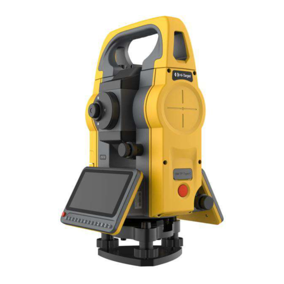
Total Station ZTS-720 series instruction manual Name of each part The names of the product components are as follows. 1 - coarse sight; 2 - objective lens focusing screw; 3 - vertical fine adjustment screw; 4 - display; 5 - eyepiece; 6 - battery compartment cover. -
Page 16: Keyboard Functions And Information Display
Total Station ZTS-720 series instruction manual Figure 2-2 Keyboard functions and information display Figure 2-3 Table 2.1 Key functions. Button Name Function Quick Configurable measurement/deposit mode, triggers measurement a measurement/deposit when clicked. keys Power Switch Controls the switch of the power supply. - Page 17 Total Station ZTS-720 series instruction manual coordinates In meters In feet In feet and inches, feet before the decimal point and hundredths of an inch after the decimal point The value along the baseline direction in point projection measurement, the direction from the starting point to the end point...
-
Page 18: Preparation Before Measurement
Total Station ZTS-720 series instruction manual C H A P T E R Preparation before measurement This chapter introduces. ▪ Instrument unpacking and storage ▪ Placement of instruments ▪ Battery loading and unloading, information and charging ▪ Reflective prisms ▪ Loading and unloading of bases ▪... -
Page 19: Instrument Unpacking And Storage
Total Station ZTS-720 series instruction manual Instrument unpacking and storage -Unboxing Gently lower the case, let its lid face up, open the locking bolt of the case, open the lid and remove the instrument. -Storage Cover the telescope mirror cover, make the vertical hand wheel of the illumination... - Page 20 Total Station ZTS-720 series instruction manual ② Rotate the foot spiral C to center the round level bubble. Screw C buble center Screw B Screw A Figure 3-1 4)Use the tube level to fine level the instrument ① Loosen the horizontal brake screw, turn the instrument so that the tube level is parallel to the line of a pair of foot spiral A and B, and then rotate the foot spiral A and B in opposite directions to center the bubble of the tube level.
- Page 21 Total Station ZTS-720 series instruction manual Figure 3-3 ③ Rotate the apparatus 90° again, and repeat steps ① and ② until the bubbles are centered in the four positions. Centering with aligner 1)Establish the tripod Extend the tripod to the appropriate height, make the three legs equal, open, and make the top surface of the tripod approximately horizontal, and located directly above the measurement site.
-
Page 22: Battery Loading And Unloading, Information And Charging
Total Station ZTS-720 series instruction manual This operation is repeated until the instrument is precisely aligned with the measurement site. Battery loading and unloading, information and charging Battery Information -- Sufficient power to operate and use. -- When this message first appears, the battery is still good for about 4 hours. -
Page 23: Reflective Prism
Total Station ZTS-720 series instruction manual pulled out of the socket when charging is finished. ▲To be charged within the temperature range of 0°~ ±45°C, beyond this range may charge abnormally. ▲Rechargeable batteries can be recharged 300-500 times, and complete discharge of the battery will shorten its service life. -
Page 24: Alphanumeric Input Method
Total Station ZTS-720 series instruction manual ③ Use the telescope focusing screw to make the target image clear. When the eye moves up and down or left and right at the end of the eyepiece, parallax is found, indicating that the focus or eyepiece diopter is not well adjusted, which will affect the accuracy of angle measurement, should be carefully focused and adjust the eyepiece tube to eliminate parallax. - Page 25 Total Station ZTS-720 series instruction manual *Enter the number [Example 2] Select the station setting mode, click on the "+" sign in the station interface, enter the coordinates of the station, click on the [N] direction input box, enter: -123.456 Method 1 Key sequence at the bottom of the screen: [-]→[1]→[2]→[3]→[.]...
-
Page 26: Instrument Registration
Total Station ZTS-720 series instruction manual Method 2 In the pop-up soft keyboard key sequence: [-]→[1]→[2]→[3]→[.] →[4]→[5]→[6] The results are shown in the following figure. Notes on USB flash drives This machine supports a maximum of USB2.0/2.1/3.0/3.1 128G USB flash drive... - Page 27 Total Station ZTS-720 series instruction manual 2)Enter the Total Station information interface, click [Register], and enter the correct registration code in the pop-up input box (please contact your dealer to obtain it). 3)After entering the correct registration code, press the [Confirm] key to indicate that the registration is successful and the displayed registration expiration time is shown correctly.
- Page 28 Total Station ZTS-720 series instruction manual Notes on instrument data storage size prompt messages 1, in the instrument memory is less than 100k, after the boot will be prompted "the disk is less than 100K, please organize data or delete data words".
-
Page 29: Software Introduction And Easy Operation Procedure
Total Station ZTS-720 series instruction manual C H A P T E R Software Introduction and Easy Operation Procedure This chapter introduces. ▪ Software Introduction ▪ Software installation ▪ Quick start... -
Page 30: Software Introduction
Total Station ZTS-720 series instruction manual Software Introduction T-Survey software is a total station software developed by Zhongda. In addition to the basic station setting and acquisition functions, it also supports a variety of release procedures, including CAD release and image-assisted release. The software also supports road, bridge and tunnel related design and release operations. - Page 31 Total Station ZTS-720 series instruction manual 2、 Set the tilt to change the compensation total station can be tilted in the X, Y direction of the instrument vertical axis caused by the angular reading error compensation correction. The compensation settings supported by the software are: open XY dual-axis compensation, open X single-axis compensation, and close compensation.
- Page 32 Total Station ZTS-720 series instruction manual II. Establishment of projects 1、 To create a new project, click [Project Management], click the blue hover [New] button on the interface (New button can be dragged), enter the project name (required), operator, notes and other information, select the required legend template, confirm that there are no errors and click OK to complete the new project.
- Page 33 Total Station ZTS-720 series instruction manual Three, set up stations The software supports users to set up stations using station hind sight, elevation transfer, rear rendezvous and point to line setting. This is illustrated here as an example of coordinate oriented station back view.
- Page 34 Total Station ZTS-720 series instruction manual IV. Acquisition The software supports various acquisition procedures such as coordinate measurement, eccentric measurement, edge-to-edge measurement, overhang height measurement, line and extension point measurement, and line and angle point measurement. The most basic coordinate measurement is explained here as an example.
- Page 35 Total Station ZTS-720 series instruction manual 2. Aim at the target point, enter the point name, legend code, target height, click [Measure] - [Record] or directly click [Measure and Save] to measure and save the prism points to the total station point library.
- Page 36 Total Station ZTS-720 series instruction manual 3. Select the desired export format, enter the file name, and click "OK" to export the total station points to the internal storage of the total station (default path: ********). Export format supports *. htf, *.txt, *.csv, *. dat, *. GSI,...
-
Page 37: Basic Measurement
Total Station ZTS-720 series instruction manual C H A P T E R Basic measurements This chapter introduces. ▪ Coordinate measurement ▪ Coordinate placement... - Page 38 Total Station ZTS-720 series instruction manual Coordinate measurement Access through [Basic Measurement] - [Coordinate Measurement] or [Acquisition Program] - [Coordinate Measurement]. "Roll call": measurement roll call, automatic accumulation by default. "Legend code": description of the measurement point, which can be entered manually or selected by clicking the button after the input box.
- Page 39 Total Station ZTS-720 series instruction manual 2. Enter [Coordinate Measurement], and the interface will display the point record image at the same time. When you measure and record the points, the points will be recorded at the same time. It should be noted that the image function is not available when the usb is inserted.
-
Page 40: Coordinate Placement
Total Station ZTS-720 series instruction manual [Measurement]: Measure the coordinates of the target point. Record]: When the target point coordinates have been measured, click Record to save the target point information to the measurement point library. [Set Station]: Jump to the station rear view screen to reset the station. - Page 41 Total Station ZTS-720 series instruction manual "Point Name Search": Perform a precise search based on the entered point name. "List Point Selection": Jump to the point library and you can select points from each point library. "Save to release point library": If checked, the currently set release points will be saved to the release point library.
-
Page 42: Set Up Stations
Total Station ZTS-720 series instruction manual C H A P T E R Set up a station This chapter introduces. ▪ Station rear view ▪ Rear view inspection ▪ Rear rendezvous ▪ Elevation transfer ▪ Point to linear station set-up... - Page 43 Total Station ZTS-720 series instruction manual Station Rear View Through [Set Station] - [Station Rear View] or "each measurement interface" - "Set Station" button to enter the station rear view interface. The station hind sight currently supports four types of orientation: coordinate...
- Page 44 Total Station ZTS-720 series instruction manual Coordinate orientation Coordinate orientation is applicable to the case where the coordinates of the survey site and the coordinates of the back view point are known. The operation steps are as follows. 1. After the user sets up the total station at the survey site, enter the [station back view] and select the coordinate orientation for the orientation mode.
- Page 45 Total Station ZTS-720 series instruction manual "Automatic calculation of instrument height": when the survey site, hind sight elevation and target height are known, you can check "Automatic calculation of instrument height", the software will automatically calculate the instrument height based on the known information.
- Page 46 Total Station ZTS-720 series instruction manual coordinates unknown. Usually used in conjunction with [Unknown Point Orientation Correction] (see Chapter operation steps are as follows. 1. After the user sets up the total station at the survey site, enter the [station hind sight] and select the unknown point orientation for the orientation mode.
-
Page 47: Rear Rendezvous
Total Station ZTS-720 series instruction manual After the user set the station, if you want to check whether the current rear view direction horizontal angle and the recorded rear view point direction horizontal angle are consistent, you can use the rear view check function, which can be accessed through [Set Station] - [Rear View Check]. - Page 48 Total Station ZTS-720 series instruction manual coordinates of the survey site through the edge rendezvous calculation. Through [Set Station] - [Rear Rendezvous] to enter the rear rendezvous interface. The operation steps are as follows. 1. Click [Rear Rendezvous] to enter the measurement interface.
- Page 49 Total Station ZTS-720 series instruction manual Angle measurement】:Click on the angle measurement when shining on the target point, and get the angle data from the measurement station to the target point. 【Measure】:Click measure when shining on the target point to get the slant distance from the measuring station to the target point.
-
Page 50: Elevation Transfer
Total Station ZTS-720 series instruction manual [Add points]:You can continue to add known points for measurement and repeat steps 2~3. 【Calculation】:Based on the current existing measurement points and the set instrument height, calculate the coordinates of the measurement site. [Return]:Return to the back rendezvous point list interface, you can continue to add points to calculate. - Page 51 Total Station ZTS-720 series instruction manual measurement interface. 2. Click "Select target point", the target point is the known point of elevation. The user can set it by "manually input elevation", "list selection" or "search point library". [OK]:After setting the elevation of the target point, click "OK" to finish the setting and return to the measurement interface.
- Page 52 Total Station ZTS-720 series instruction manual 【Measure】:Click measure when shining on the target point to get the slant distance from the measuring station to the target point. Record]:After you have measured the target point, click "Record" to return to the point list and record the distance measurement point to the measurement point library.
-
Page 53: Point To Linear Set Up Station
Total Station ZTS-720 series instruction manual [Return]:Return to the elevation transfer point list interface, you can continue to add points to calculate. 【Application】:Apply the calculated elevation to the current measurement site, and the Z coordinate of the measurement site in the point database is changed correspondingly. - Page 54 Total Station ZTS-720 series instruction manual target height according to the instruction, click "Measure" for the end point of the reference line, and then click "Next". 3. Enter the point-to-station interface. Continue to align the end point of the reference line (as the rear view point), enter the point name, legend code and instrument height of the station, and click "OK"...
-
Page 55: Collection Procedure
Total Station ZTS-720 series instruction manual C H A P T E R Collection procedure This chapter introduces. ▪ Coordinate measurement ▪ Single pitch eccentric ▪ Planar eccentricity ▪ Cylindrical eccentricity ▪ Edge-to-edge measurement ▪ Overhang height measurement ■ Line... - Page 56 Total Station ZTS-720 series instruction manual Coordinate measurement See Chapter 2 [Basic Measurement] - [Coordinate Measurement]. Single pitch eccentric If the point to be measured (P) is known to deviate from the eccentric point (T0) in the observation direction of the front and rear, left and right eccentricity, then the coordinates of the T0 point can be measured by the monodistance eccentricity function.
- Page 57 Total Station ZTS-720 series instruction manual [Record]:Record the eccentric points obtained by calculation to the point library. [Next point]:You can recalculate the next point from step 1. Planar eccentricity This function is used to determine points that cannot be measured directly, such as determining the distance or coordinates of a plane edge.
-
Page 58: Cylindrical Eccentric
Total Station ZTS-720 series instruction manual Then the instrument calculates and displays the coordinates of the point of intersection of the alignment axis and the plane - the coordinates of point P0. [Record]:Record the eccentric points obtained by calculation to the point library. - Page 59 Total Station ZTS-720 series instruction manual 2. Aim at the second point P2 on the edge of the cylinder and click "Next" to get the horizontal angle data while going to the next step. 3. Aim at point P on the cylindrical surface and click "Measure" to get the azimuth and distance data.
- Page 60 Total Station ZTS-720 series instruction manual 4. Click "Next" to derive the coordinates of the center of the cylinder, you can choose [record], [next point]. Measurement on the opposite side After measuring a series of points, you can connect the target points by "ray" or "line"...
- Page 61 Total Station ZTS-720 series instruction manual You can enter the interface of edge measurement through [Acquisition Program] - [Edge Measurement]. The operation steps are as follows. 1. After the user sets up the station, click [Measure on the side] to enter the measurement interface.
-
Page 62: Overhang Height Measurement
Total Station ZTS-720 series instruction manual 3. After measuring 2 or more points, you can switch to the [Result] page to view the edge-to-edge measurement results. The radio box at the bottom of the data page can choose the calculation method of "ray to edge" or "fold to edge". - Page 63 Total Station ZTS-720 series instruction manual 2. Illuminate the target point T and derive the suspension height value in real time. Previous]:Return to the previous step, you can view the previous measurement information. 【Finish】:Restart the suspension height measurement. Reference point overhang height The ground overhang height is used to calculate the distance from the target point to the reference point without filling in the target height.
- Page 64 Total Station ZTS-720 series instruction manual 2. Align the reference point R, the software calculates the reference height difference in real time, click [Next]. 3. Illuminate the target point T, and the software calculates the suspension height value in real time.
-
Page 65: Line And Extension Point Measurements
Total Station ZTS-720 series instruction manual Line and extension point measurements When the point to be measured is on the line of two measurable points and the distance from the point to be measured to the last measurement point is known, the [Line and Extension Point Measurement] (two distance eccentricity) function can be used for calculation. -
Page 66: Line And Corner Point Measurement
Total Station ZTS-720 series instruction manual [Record]:Record the target points obtained by calculation to the point library. [Next line]:You can recalculate the next point from step 1. Line and corner point measurement When the point to be measured is on the line of two measurable points, but the... - Page 67 Total Station ZTS-720 series instruction manual 3. Shine the light on the target point, and the software displays the calculated coordinates of the target point. [Record]:Record the target points obtained by calculation to the point library. [Next line]:You can recalculate the next point from step 1.
- Page 68 T-Survey Total Station Software User Manual C H A P T E R Placement procedure This chapter introduces. ▪ CAD proofing ▪ Coordinate placement ▪ Image Assisted Release ▪ Angular Distance Release ▪ Directional line placement ▪ Straight line placement ▪...
-
Page 69: Cad Release
Total Station ZTS-720 series instruction manual CAD Release CAD release allows you to select features from imported dxf and dwg format files and perform point release and line release on the selected features. CAD data import Click [Release Program] → [CAD Release] to enter the CAD release interface,... - Page 70 Total Station ZTS-720 series instruction manual Delete base image After importing external data, click the [Data] button in the CAD release interface to enter the data interface, click the [Clear Base Map] button in the upper right corner of the interface, a pop-up window will appear to indicate whether to confirm the deletion of the CAD base map file, click OK to clear the base map.
- Page 71 Total Station ZTS-720 series instruction manual you click Open, the last file will be loaded; otherwise, it will not be loaded. Note: 1. When switching between projects and the New function is performed, the CAD release screen correctly displays the imported data and is not affected.
- Page 72 Total Station ZTS-720 series instruction manual independent entities. Line Plotting 1. importing the CAD files to be released for sampling. 2. Click to select the target line to be released, and display the "Release" button. 3. Click "Release" button to enter the release parameter setting interface, you can set the release parameters such as left/right offset, front/back offset, front/back offset increment, top/bottom offset, etc.
- Page 73 Total Station ZTS-720 series instruction manual and expand the graphic interface on the right to display the position relationship between the current position, prism points and release points. Point Release For CAD interface graphics, you can use the [Select Point] button to select special marker points, and click OK after successful selection to release the selected points.
-
Page 74: Coordinate Placement
Total Station ZTS-720 series instruction manual storage/measurement-record to calculate the release information, according to which the prism can be moved to the position to be released. Coordinate Placement The coordinates can be selected by the point library or manually entered to select a certain release point for the release operation. - Page 75 Total Station ZTS-720 series instruction manual 2. After selecting the release point, click OK, return to the release interface, click the previous point and next point button to switch the point data in the release point library for release. 3. The total station illuminates the prism, click on the measurement and storage/measurement-record to calculate the release information, and refer to the release information tips to find the release position.
-
Page 76: Image-Assisted Release
Total Station ZTS-720 series instruction manual Image Assisted Release The total station is equipped with image function, which will display the camera view on the screen. When the release point is set, it will mark the location of the release point on the interface and perform the release prompt to the left/right and up/down. -
Page 77: Angular Distance Release
Total Station ZTS-720 series instruction manual 3. According to the instructions to turn the eyepiece, when the target point in the visual range, you can see a red mark on the target point. It is convenient to take a picture and put the sample. - Page 78 Total Station ZTS-720 series instruction manual Click [Angular Distance Release] to enter the angular distance setting interface, set the horizontal angle, angular distance and height difference from the release point to the survey site. Click OK to jump to the angle and distance release interface, and click angle and distance parameters to modify and adjust the release point setting parameters.
-
Page 79: Directional Line Placement
Total Station ZTS-720 series instruction manual Directional line placement Directional line placement can be set by inputting azimuth, level distance and elevation difference from reference point to reference point to set the placement point for placement. Click [Directional Line Placement] to enter the directional line parameter setting interface, after selecting the reference point (the reference point can be selected by manual input, list selection, measurement selection, etc.), set the azimuth, flat... -
Page 80: Straight Line Plotting
Total Station ZTS-720 series instruction manual Straight Line Plotting Straight Line Placing allows you to place custom lines by setting the placing parameters. Click [Line Release] to enter the line definition interface, set the starting point and end point to create a custom line. -
Page 81: Reference Line Placement
Total Station ZTS-720 series instruction manual Click "Line Definition" to modify and adjust the line information. Click the previous point and next point button to switch the target points according to the configuration of the release parameters, click the measurement and... - Page 82 Total Station ZTS-720 series instruction manual Reference line placement After defining the reference line and its baseline offset, click OK to enter the setting interface of release parameters, set the release parameters such as left/right offset, front/back offset, front/back offset increment, top/bottom offset, etc., and then click OK to enter the reference line release interface.
-
Page 83: Reference Arc Release
Total Station ZTS-720 series instruction manual release according to the offset increment. After target point selected, click measurement storage/measurement-record to calculate the release information, and expand the graphic interface on the right side to show the position relationship between the current position, prism points and release points. - Page 84 Total Station ZTS-720 series instruction manual after selecting the reference arc definition method, you can set the parameters as required. After "Center + Start" or "Start + End + Point on Arc", click "Calculate" button to automatically solve the reference arc radius information.
- Page 85 Total Station ZTS-720 series instruction manual method to calculate the radius of the reference arc, only the 2D projection coordinates are considered, i.e. the radius is calculated in the 2D plane, independent of the Z coordinate of the reference point.
- Page 86 Total Station ZTS-720 series instruction manual Release arc Select the arc release item, set the closing difference, starting arc distance, diameter distance, arc increment and other parameters and then click OK to jump to the reference arc release interface, click Save/Measure-Record to calculate the release information, and expand the right graphical interface to display the current position, prism points, and the position relationship between the release points.
- Page 87 Total Station ZTS-720 series instruction manual evenly divided closure difference, and end point closure difference. If end point mode is selected, the remainder of the total arc length/arc increment when the release point switching is performed is attributed to the last release point, and so on for other modes.
- Page 88 Total Station ZTS-720 series instruction manual Release strings Select the chord item, set the closing difference, starting chord length, diameter distance, chord increment and other parameters and then click OK to jump to the reference arc release interface, click Save/Measure/Record to calculate the release information, and expand the graphic interface on the right to display the current position, prism points and the position relationship between the release points.
- Page 89 Total Station ZTS-720 series instruction manual Release sample rounding angle Select the release center angle item, set the closing difference, starting center angle, diameter distance, angle increment and other parameters and then click OK to jump to the reference arc release interface, click Save/Measurement-Record to...
- Page 90 Total Station ZTS-720 series instruction manual...
-
Page 91: Calculation Tools
Total Station ZTS-720 series instruction manual C H A P T E R Calculation Tools This chapter introduces. ▪ Unknown point orientation correction ▪ Orientation-free calibration Coordinate orthorectification ▪ Coordinate backcalculation ▪ Area perimeter ▪ Angle conversions ▪ Distance conversion ▪... - Page 92 Total Station ZTS-720 series instruction manual Unknown point orientation correction The unknown point orientation correction function is used to post-process the data recorded from the unknown point orientation set-up measurements, i.e., to perform hind sight correction. The module can be accessed through [Calculation Tools] - [Unknown Point Orientation Correction].
- Page 93 Total Station ZTS-720 series instruction manual selected hind view point coordinates. Orientation-free calibration The orientation-free correction function is used to post-process data recorded from orientation-free set-up measurements, i.e., to perform hind-sight correction. It is divided into known point method and common point method. The module can be accessed through [Calculation Tools] - [Orientation-free Correction].
- Page 94 Total Station ZTS-720 series instruction manual 2. Click on the list selection button after the measurement point to select the measurement point for which you know the correct coordinates. 3. Enter or list select the known coordinates corresponding to the measurement point at the known coordinates.
- Page 95 Total Station ZTS-720 series instruction manual between the known point coordinates and the actual observed value is more than 10cm, the correction will not be successful. Common Point Method The common point method is used for hindcast correction in the case where two different stations have been set up without orientation in the same coordinate system, and two different stations have observed the same prismatic point.
-
Page 96: Coordinate Orthogonal Calculation
Total Station ZTS-720 series instruction manual 4. After setting, click [Calibration]. If the calibration is successful, the corresponding measurement coordinates of both stations in the point data are modified to the corrected coordinates. Coordinate orthogonal calculation The coordinate orthogonal calculation function can derive the specific coordinate information of the end point by setting the spatial relationship between the start point and the end point relative to the start point. -
Page 97: Coordinate Backcalculation
Total Station ZTS-720 series instruction manual Coordinate backcalculation The coordinate back-calculation function can derive the spatial information of the end point with respect to the start point from the coordinate information of the start point and the end point. The start point and end point can be input and selected by manual input, list selection and measurement selection, etc. -
Page 98: Area Perimeter
Total Station ZTS-720 series instruction manual Area perimeter Click to enter the area perimeter, you can select multiple point data to form the group of polygon vertices that need to calculate the area by manual input, list selection of points, measurement selection of points, etc. -
Page 99: Angle Conversion
Total Station ZTS-720 series instruction manual Click Calculate after you finish the selection, you can jump to the result interface to view the calculation results, including graphical results and area length data results. Angle conversion Supports the conversion of radians, degrees, gauges, minutes, mils, and degrees-minutes-seconds units to each other. -
Page 100: Distance Conversion
Total Station ZTS-720 series instruction manual Distance Conversion Support converting each distance unit of kilometer, meter, centimeter, millimeter, yard, mile, foot, inch and nautical mile to each other. After entering the value in any item, click [Calculate] to calculate the value in other formats. -
Page 101: Slow Curve Calculation
Total Station ZTS-720 series instruction manual Slow Curve Calculation Users can click [Calculation Tools] - [Gentle Curve Calculation] to enter this interface and calculate the gentle curve parameters, starting half-longitude and ending radius by this function. - Page 102 Total Station ZTS-720 series instruction manual Line Segment Equivalents The line segments are divided into equal parts according to two types of equal parts: constant number equal parts and constant distance equal parts. You need to input the coordinates of start point and end point, there are three input methods, which are manual input, list selection, and measurement selection.
-
Page 103: Calculators
Total Station ZTS-720 series instruction manual Calculators Tool for performing simple mathematical calculations. -
Page 104: Project Management
T-Survey Total Station Software User Manual C H A P T E R Project Management This chapter introduces. ▪ Project Management ▪ Point Library ▪ Legend coding... - Page 105 Total Station ZTS-720 series instruction manual Project Management Enter the project management interface, you can view the current project properties, legend codes and other information, open, delete or view the history of projects, create new projects and other operations. Open Project]: Click the project you need to open, click "Open" to open the selected project.
- Page 106 Total Station ZTS-720 series instruction manual If the current total station has been inserted into an external USB flash drive, you can also copy the items in the USB flash drive to local storage, view the properties and delete them.
-
Page 107: Point Library
Total Station ZTS-720 series instruction manual Point Library The point library can be accessed from the main screen or from the top bar of any measurement screen at icon. Point bank generic functions. 1. Click [Graph] in the upper right corner to view the display of each type of point on... - Page 108 Total Station ZTS-720 series instruction manual 2. Click "..." - [Clear] in the upper right corner to clear all points. 3. Click "..."-[Settings] in the upper right corner to set the loading order and the number of loading. 4. Click a point library data, you can choose to "edit" or "delete" the data. If there is a...
- Page 109 Total Station ZTS-720 series instruction manual 5. Enter a full or partial name in the name input box, and click "Search" to search for a point. All points When the point library is switched to select all points, the interface displays the NEZ and legend code information of all points (measurement points, release points, control points).
- Page 110 Total Station ZTS-720 series instruction manual Click the hover button at the bottom right corner - "Import", you can import the sample/control points. Select the type of points you want to import (release points/control points) in the top bar, and then select the file to import. The detailed import operation is shown in the section of "Sample Points".
- Page 111 Total Station ZTS-720 series instruction manual Click on the hover button at the bottom right corner - "Export" to export the measurement points. Select the desired export format, enter the file name and click "OK" to export the measurement points to the total station memory. Currently, the supported export formats are *.
- Page 112 Total Station ZTS-720 series instruction manual entrance is the hover button at the bottom right corner. Add]: Click the hover button-[Add] to enter the interface of adding release points. You can select points in the list or manually input to add sample points.
- Page 113 Total Station ZTS-720 series instruction manual click "OK" to complete the data import. ① Select the fields to be imported in the "Selectable Fields" list, the selected fields will be automatically populated in the "Selected Fields" list, click the button to select/unselect all fields.
-
Page 114: Legend Code
Total Station ZTS-720 series instruction manual entrance and operation steps are the same as [Release Point], so we will not repeat here. Legend Code The legend code can be accessed from the top bar of the project management interface. "Type selection": click the type drop-down box, the available legend types are "all", "point", "line"... - Page 115 Total Station ZTS-720 series instruction manual "Group editing": click "Group" in the upper right corner to enter group editing. You can "add", "delete", "edit" and other operations to the group. No group can be deleted or edited. [Add]: Click the Add Hover button at the bottom right corner and enter the group name.
- Page 116 Total Station ZTS-720 series instruction manual "Legend code deletion": click a legend code data and click [Delete] to delete the code. "Add legend code": click the hover button at the bottom right corner - "Add" to enter the add interface, you can add the legend code.
- Page 117 Total Station ZTS-720 series instruction manual in xml format.
-
Page 118: Road
Total Station ZTS-720 series instruction manual C H A P T E R Roads This chapter introduces. ▪ Road design ▪ Line calculation ▪ Road sampling ▪ Structure placement... - Page 119 Total Station ZTS-720 series instruction manual Road design Click Road -> Road Design to enter the road library interface, you can add road data by manually creating or importing road files, and also edit, delete and export the existing roads.
- Page 120 Total Station ZTS-720 series instruction manual Add]: Click the "+" button to enter the broken link adding interface. Edit the pile name, enter the previous mileage and the next mileage, click "OK", and the completed broken link pile can be viewed under the broken link pile list.
- Page 121 Total Station ZTS-720 series instruction manual "Apply" button, it will return to the "Road Design" interface and prompt "broken link data has been updated". Flat section design line The flat section design supports the use of the intersection method and the line element method.
- Page 122 Total Station ZTS-720 series instruction manual Select [Intersection Method] to enter the intersection table data editing interface. Add]: Click "+" button to add the intersection data, get the intersection name, N, E, intersection mileage (only the mileage of the first two points need to be entered)
- Page 123 Total Station ZTS-720 series instruction manual [Edit]: You can edit the already inputted intersection data. [Insert]: Insert an intersection data above the selected point. [Delete]: Delete the selected intersection data. Involving virtual intersection and turn-back (turning more than 180 degrees) curves, in addition to the line element method can be supported, in the intersection method, the corresponding virtual intersection point switch is supported.
- Page 124 Total Station ZTS-720 series instruction manual Line Element Method The line element legal line is also called the building block legal line, which is a combination of complex highway plane line "whole into zero" decomposition into a number of line units. If the starting point information of the route plane curve is...
- Page 125 Total Station ZTS-720 series instruction manual Starting Point]: Click "Starting Point" to enter the starting point interface to edit the starting point information. 【Graph】 :See the intersection method Apply】 :After the line element method data has been edited, click "Apply" to upd ate the current data.
- Page 126 Total Station ZTS-720 series instruction manual Setting]: You can set the starting mileage, ending mileage, mileage interval, offset distance and staking method for flat section mileage data export, click OK to apply successfully, and return to the stake-by-stake table interface at the same time.
- Page 127 Total Station ZTS-720 series instruction manual In the general working process, click to add variable slope point data including: variable slope point mileage, variable slope point elevation, radius (longitudinal curve radius), and add all the elements of variable slope points of the line in the order of mileage in turn.
- Page 128 Total Station ZTS-720 series instruction manual [Add]: Click the Add button at the bottom right corner to choose to add left/right cross-sectional panels. "Name": the name of the board is entered. "Slope": from the road centerline outward, the slope of the slab is positive for uphill and negative for downhill.
- Page 129 Total Station ZTS-720 series instruction manual To reduce the centrifugal force generated by the vehicle driving on the curved road, the road is made into a one-way cross slope in the form of high outside and low inside called super high.
- Page 130 Total Station ZTS-720 series instruction manual The super height is located in the "left side of the motor vehicle" section, entered as follows. To simplify the example, we assume that the ultra-high change points on the drawing read as follows.
- Page 131 Total Station ZTS-720 series instruction manual Ultra High Change Point 3: Mileage 20 Slope 2% Ultra High Change Point 3: Mileage 30 Slope -1.5% Finish adding the four ultra-high points in turn, and you can view them correspondingly in the [Graph] screen.
- Page 132 Total Station ZTS-720 series instruction manual Widening In order to transition the pavement from the normal width to the curve, a widened width is set so that a widening mitigation section is required. On the widening mitigation section, the pavement has a gradually changing width. The setting of widening transition can be used in different ways according to the nature and grade of the road.
- Page 133 Total Station ZTS-720 series instruction manual To simplify the example, we assume that the widening change point on the drawing reads as follows. Widening change point 1: Mileage 0 Width 4.5 Widening change point 2: Mileage 10 Width 5.2 Widening change point 3: Mileage 20 Width 6 Widening change point 4: Mileage 30 Width 5.2...
- Page 134 Total Station ZTS-720 series instruction manual Click "Graph" to enter the preview interface, and click "Cross Section" button to view the cross section widening information of the current position corresponding to the mileage. Note: you can switch any [standard], [super high], [widening] to view the data entry, to confirm that the three interfaces are correct, any click on the "application"...
- Page 135 Total Station ZTS-720 series instruction manual elevation and cross slope, and click "OK" to complete structure design. Add】 :New road structure, click "+" button in the structure information interface to select the structure type and practice, enter the mileage value, angle, forward width, backward width, left length, right length, center elevation and cross slope, click "OK "...
-
Page 136: Road Release
Total Station ZTS-720 series instruction manual you can view the designed structure graphics, click the top structure selection bar to switch other structure graphics display. Apply】 :Click "Apply" button to update the structure design data. Line Calculation After the current project has existed road data, click to enter the "line calculation"... - Page 137 Total Station ZTS-720 series instruction manual Enter the road sampling interface, you can sample the current road data, you can also switch the road library has existed other road data for sampling. The steps of the sampling operation are as follows.
- Page 138 Total Station ZTS-720 series instruction manual 3.Road release: After setting the mileage increment, you can switch the target points by clicking the previous point and next point button in the release interface with the mileage increment as the interval (if the mileage increment is 0, the previous...
-
Page 139: Structure Release
Total Station ZTS-720 series instruction manual Structure release The structure sampling interface can be used to sample the feature points of the structure data in the road data. The steps of the release procedure are as follows. 1. Select road data: click the "Road" button, jump to the road library, click to select the road data need to be put back to the sample interface. - Page 140 Total Station ZTS-720 series instruction manual column and feature point column respectively to select the structure and its feature points that need to be released for the current road data. 3. Structure release: After selecting the feature points to be released, click...
- Page 141 Total Station ZTS-720 series instruction manual...
-
Page 142: Bridges
Total Station ZTS-720 series instruction manual C H A P T E R Bridges This chapter introduces. ▪ Pier formwork library ▪ Bridge arrangement ▪ Cone slope design library ▪ Pier placement ▪ Tapered slope release... - Page 143 Total Station ZTS-720 series instruction manual Pier formwork library Bridge pier is the collective name of bridge pier and bridge abutment, which is the building supporting the superstructure of the bridge. The overall steps of pier and abutment release with T-Survey software are: ① enter [Pier and Abutment Formwork Library] to design pier and abutment formwork;...
- Page 144 Total Station ZTS-720 series instruction manual The parameters to be set are template name, angle and layout method. (0,180) when the layout method is orthogonal, and (0,180) when the layout method is oblique intersection vertical distance or oblique intersection oblique distance.
-
Page 145: Bridge Arrangement
Total Station ZTS-720 series instruction manual the horizontal and vertical axis determined by the pier angle as the reference, calculate the horizontal mirror, vertical mirror and horizontal and vertical mirror points, that is, a total of three mirror points. 5. After the completion of the feature point settings, click "OK" to return to the... - Page 146 Total Station ZTS-720 series instruction manual 2. Go to [Bridge Layout] and select the designed road at the top bar. 3. After selecting the road, click the "Add" hover button at the bottom right corner to enter the new bridge interface. The parameters you need to set are the bridge name.
-
Page 147: Cone Slope Design Library
Total Station ZTS-720 series instruction manual is not editable, and it is directly displayed as the angle in the template by default. "Check offset first, then rotate": use the axis as a reference, first offset based on "axis offset", then rotate based on "axis angle". - Page 148 Total Station ZTS-720 series instruction manual cone slope; ② enter [Cone Slope Sampling] and sample the target points of cone slope according to the set equal fraction. The cone slope design on T-Survey is based on the road, i.e., the road design is required before designing the cone slope.
-
Page 149: Pier Placement
Total Station ZTS-720 series instruction manual 4. After the cone slope setting is finished, click "OK" to return to the cone slope design library, that is, to complete a cone slope design. Click a tapered slope in the tapered slope design list to "delete"/"edit" the tapered slope. - Page 150 Total Station ZTS-720 series instruction manual 2. Feature point selection: After selecting the road data, click the bridge column, pier column, feature point column, respectively, to select the current road data need to put the bridge, pier and its feature points.
-
Page 151: Cone Slope Release
Total Station ZTS-720 series instruction manual and expand the graphic interface on the right side to show the position relationship between the current position, prism points and release points. 、 Cone Slope Release The cone slope release interface can release the target points of cone slope in the road data. - Page 152 Total Station ZTS-720 series instruction manual 2. Target point selection: After selecting the road data, click on the cone slope column to select the cone slope of the current road data that needs to be released. The software will pop up the number of equal fraction settings, and after the setting is completed, the target point column will display the corresponding number of target points according to the number of equal fractions.
- Page 153 Total Station ZTS-720 series instruction manual 3. Cone slope sampling: After selecting the target points to be sampled, click on the measurement and storage/measurement-record to calculate the sampling information and expand the graphic interface on the right to show the position...
-
Page 154: Tunnel
Total Station ZTS-720 series instruction manual C H A P T E R Tunnel This chapter introduces. ▪ Tunnel Section Library ▪ Tunnel feature points ▪ Tunnel over-excavation... - Page 155 Total Station ZTS-720 series instruction manual Tunnel Cross Section Library Depending on the tunnel construction stage, tunnel sections can be roughly divided into excavation, primary support and second lining. The overall steps of tunnel over-excavation using T-Survey software are: ① enter [Tunnel Section Library] to design the tunnel section (excavation, primary support, second lining);...
- Page 156 Total Station ZTS-720 series instruction manual Different section types design section process and methods are the same, the parameters to be set are name, offset in tunnel and section line element. 4. In the tunnel section design interface, click the hover "Add" button to bring up the section line element selection box, the options are "straight line", "arc"...
- Page 157 Total Station ZTS-720 series instruction manual If you select the section line element type as arc, you have the following three options to add. ①"Start point - End point - Turning angle": the parameters to be set are start height difference, start offset, end height difference, end offset, and rotation angle (cannot be 0).
- Page 158 Total Station ZTS-720 series instruction manual ③"Start point-circle center-rotation angle": the parameters to be set are start height difference, start eccentricity, circle center height difference, circle center eccentricity, rotation angle (cannot be 0). If the section line element type is selected as circle, the parameters to be set are circle center height difference, circle center offset, and radius (cannot be 0).
- Page 159 Total Station ZTS-720 series instruction manual element and the tunnel centerline. Click "..." -> "Clear" in the upper right corner to clear the list of section line elements. 6. Click "Save" to complete a tunnel section design. Click a section in the tunnel section list, you can "delete"/"edit" the section operation.
- Page 160 Total Station ZTS-720 series instruction manual 3. After selecting the road, select the type of section where the feature points are located (excavation, primary support, second lining), click the bottom right corner of the "Add" hover button to enter the tunnel feature point design interface.
-
Page 161: Tunnel Over-Under-Excavation
Total Station ZTS-720 series instruction manual Click a feature in the tunnel feature list to "delete"/"edit" the feature. Click "..." -> "Clear" in the upper right corner to clear the list of tunnel feature points. Tunnel over-under-excavation The tunnel over- and under-excavation module can measure the target point and then determine the over-/under-excavation type and value based on the currently selected cross-section. - Page 162 Total Station ZTS-720 series instruction manual 2. Target selection: After selecting the road data, click the section type column, tunnel section column, target column, select the current road data need to tunnel over and under excavation section or feature points.
- Page 163 Total Station ZTS-720 series instruction manual 4. "To mid-tunnel point/feature point XX": If you select to mid-tunnel point or to feature point in the target column, click Save/Measure, the target angle and distance will be displayed on the right side, as well as the left/right distance, front/back...
-
Page 164: Configuration
Total Station ZTS-720 series instruction manual C H A P T E R Configuration This chapter introduces. ▪ Distance measurement parameters configuration ▪ Total station configuration ▪ Measurement aid configuration ▪ Unit/display configuration ▪ Total station calibration ▪ Total Station Information & Registration... - Page 165 Total Station ZTS-720 series instruction manual Distance measurement parameters configuration Users can click [Configuration] - [Ranging Parameters Configuration] to enter this interface. Only the total station installation software can set this item, other Androidid devices do not display the [Range parameter configuration] item.
- Page 166 Total Station ZTS-720 series instruction manual Reflector The available reflectors are: prism-free, prismatic and reflective sheet. It is important to note that the selected reflector needs to be consistent with the actual reflector, otherwise it may affect the accuracy or measurement failure.
- Page 167 Total Station ZTS-720 series instruction manual Automatic acquisition: The temperature and air pressure values in the current environment are automatically measured by the internal sensors of the total station. Gridding factor The default grid factor is 1, which can be obtained by scale factor and average elevation calculation.
- Page 168 Total Station ZTS-720 series instruction manual Total Station Configuration Users can click [Configuration] - [Total Station Configuration] to enter this interface. Only the total station installation software can set this, other Androidid devices do not show [Total Station Configuration] item.
- Page 169 Total Station ZTS-720 series instruction manual "Single screen adaptation": the screen on one side of the operation is on, and the screen on the other side is off. "Double screen with display": both screens remain always on at the same time.
- Page 170 Total Station ZTS-720 series instruction manual The full configuration is displayed when the total station is installed. Other Androidid devices show partial configuration when installed. [Reset]: Click Reset in the upper right corner to reset the parameters of the current interface to the factory default values.
- Page 171 Total Station ZTS-720 series instruction manual coordinate measurement, and save the photo of the point at the same time. And you can view it in the measurement point library. Rename tips Open this item and it cannot save the rename point.
- Page 172 Total Station ZTS-720 series instruction manual Distance unit Used to set each length input box and distance display unit of the software. Temperature units Used to set temperature units, mainly for atmospheric corrections. Barometric unit Used to set barometric pressure units, mainly for atmospheric correction.
- Page 173 Total Station ZTS-720 series instruction manual Horizontal angle Used to set the horizontal angle display of the measurement interface. Vertical angle Used to set the vertical angle display of the measurement interface. Angle reading Used to set the accuracy of the angle display of the measurement interface.
- Page 174 Total Station ZTS-720 series instruction manual Distance reading Used to set the accuracy of the distance display of the measurement interface. Coordinate order Used to set the interface NEZ display order. Soft Keyboard...
- Page 175 Total Station ZTS-720 series instruction manual "Full keyboard": soft keyboard will pop up when either numeric or text input box is selected. "Text input only": soft keyboard pops up when only the text input box is selected. Total Station Calibration...
- Page 176 Total Station ZTS-720 series instruction manual Click the "Register" button at the bottom to register your Total Station hardware. When installed on other Androidid devices, the total station information can be used to connect to the device in "demo mode" and "Wifi".
- Page 177 Total Station ZTS-720 series instruction manual as "Wifi", and follow the guide to complete the total station connection. After the connection is completed, the basic information of the connected total station will be displayed.
-
Page 178: Quick Menu
Total Station ZTS-720 series instruction manual C H A P T E R Quick Menu This chapter introduces. ▪ Laser down to point ▪ Atmospheric Correction ▪ Prismatic constants ▪ Scoreboard lighting ▪ Custom function keys ■ FTP ▪ Total station registration/connection... - Page 179 Total Station ZTS-720 series instruction manual The shortcut menu can be opened by clicking on the top bar , which is the left side slider bar. The full configuration is displayed when installed on the Total Station, the partial configuration is displayed on other Androidid devices.
-
Page 180: Atmospheric Correction
Total Station ZTS-720 series instruction manual Atmospheric Correction Atmospheric correction can be calculated by temperature and pressure or input directly. The setting here has the same effect as setting in [Ranging Parameters Configuration]. Prismatic constants The prism constant of the prism can be set. The setting here has the same effect... -
Page 181: Custom Function Keys
Total Station ZTS-720 series instruction manual as setting in [Ranging Parameters Configuration]. Divider lighting Set the illumination level of the scoreboard for illumination during nighttime measurements. Custom Function Keys Used to set the shortcut jump parameters of the physical keys of the total station,... -
Page 182: Ftp
Total Station ZTS-720 series instruction manual Used for FTP transfer parameters, can be used for file transfer. By default, the software does not check "Transfer without encryption", users need to enter user name, password and port. If "Transfer without encryption" is checked, the software does not display the user name and password input box, and the user only needs to configure the port. -
Page 183: Total Station Registration/Connection
Total Station ZTS-720 series instruction manual Total Station Registration/Connection Total station registration can enter the interface of total station information and perform registration operation, which is consistent with the function of configuration- total station information; the cell phone terminal shows total station... - Page 184 Total Station ZTS-720 series instruction manual...
-
Page 185: Top Shortcut Function
Total Station ZTS-720 series instruction manual C H A P T E R Top shortcut function This chapter introduces. ▪ Distance measurement mode ▪ Tilt compensation ▪ Reflector type switching ▪ Laser pointing ▪ Point data ■ More... - Page 186 Total Station ZTS-720 series instruction manual Distance measurement mode Click on the top bar to set the ranging mode, and you can set the mode as follows. The setting here has the same effect as the setting in [Ranging Parameters Configuration].
-
Page 187: Point Data
Total Station ZTS-720 series instruction manual Click the top bar to turn the objective pointing laser on or off. This setting has the same effect as the setting in [Ranging Parameters Configuration]. Point Data Click the top bar to enter the point library to view the measurement points, release points and control points. - Page 188 Total Station ZTS-720 series instruction manual Exit Software Click this item to bring up the exit confirmation box, which can be used to exit the software.
-
Page 189: Inspection And Calibration
Total Station ZTS-720 series instruction manual C H A P T E R Inspection and Calibration This chapter introduces. Tube level ▪ Round level ▪ Telescope dividers ▪ Perpendicularity of the visualization axis to the horizontal axis ▪ Automatic compensation of zero point of vertical disc indicator ▪... -
Page 190: Tube Level
Total Station ZTS-720 series instruction manual Tube level -Check The method is described in the book "Accurate leveling instruments with tube level". -Correction 1、In the inspection, if the bubble of the tube level deviates from the center, first use the foot spiral parallel to the tube level to adjust it, so that the bubble moves to the center nearly half of the deviation amount. -
Page 191: Perpendicularity Of The Visual Alignment Axis To The Horizontal Axis
Total Station ZTS-720 series instruction manual 2. Turn the vertical micro hand wheel of the telescope so that point A moves to the edge of the field of view (point A′). 3、If the A point is moving along the vertical wire of the cross wire, that is, the A′... -
Page 192: Vertical Disc Indicator Zero Point Automatic Compensation
Total Station ZTS-720 series instruction manual 2. Aim the telescope at target A in the left position of the disk and read the horizontal angle. Example: Horizontal angle L = 10°13′10″ 3、Loosen the vertical and horizontal hand wheel, rotate the telescope, rotate the right side of the illumination plate to align the same target A. - Page 193 Total Station ZTS-720 series instruction manual 2、After the power is turned on, the vertical disk indicator is zeroed, the vertical hand wheel is tightened, and the instrument displays the value of the current vertical angle at which the telescope points.
- Page 194 Total Station ZTS-720 series instruction manual Figure 17-4 2) Select the parameter item to be calibrated and enter the corresponding calibration interface. Figure 17-5 3) Follow the instructions at the bottom of the interface until the calibration is finally completed.
-
Page 195: Aligner
Total Station ZTS-720 series instruction manual the indicator difference still does not meet the requirements, you should check whether the step operation of the correction indicator zero setting (the vertical angle shown in the zero setting process is the value without compensation and correction, only for reference in the setting and not for other purposes) is wrong, and whether the target illumination is accurate, etc., and then set it again as required. - Page 196 Total Station ZTS-720 series instruction manual 地面十字丝中心 Figure 17-6 5. Repeat inspection step 4 and check the calibration until it meets the requirements. 6, for the laser under the point, then unscrew the laser cover, use 1 # hexagonal wrench to adjust the three screws, while tightening and loosening, and finally adjust the laser spot to 0 point.
-
Page 197: Prism-Free Distance Measurement
Total Station ZTS-720 series instruction manual has changed, the user, if required to make corrections, will set the instrument plus the constant according to the value of the integrated constant K. For example, if the K value measured by the above method is -5, and the original instrument constant in the instrument is -20, the newly set value is -20 - (-5) = -15. - Page 198 Total Station ZTS-720 series instruction manual checked for any offset, otherwise it may lead to inaccurate ranging. Warning. Looking directly at the laser is usually dangerous. Prevention. Do not look directly at the laser beam, or shine it at others. Measurements may also be obtained by reflected light from the human body.
-
Page 199: Appendix A Symbol Meanings
Total Station ZTS-720 series instruction manual Appendix A Symbol Meaning Take the following example to illustrate the meaning of the symbols Zenith distance mode Vertical angle display mode of 0 when the telescope is horizontal at the positive mirror Vertical angle mode (0 when horizontal, positive elevation angle, negative... - Page 200 Total Station ZTS-720 series instruction manual FCC Statement This equipment has been tested and found to comply with the limits for a Class B digital device, pursuant to part 15 of the FCC Rules. These limits are designed to provide reasonable protection against harmful interference in a residential installation.
Need help?
Do you have a question about the ZTS-720 Series and is the answer not in the manual?
Questions and answers