Table of Contents
Advertisement
Quick Links
All manuals and user guides at all-guides.com
Thank you for choosing ZTS-120/120R. As your handy
construction tool, it will provide you with the most efficient and
economic solutions to your job. To fully utilize the potential of
your instrument and protect your investment, you need to, as we
strongly suggest, thoroughly read this manual before starting any
operations. Should you run into any problems, Hi-Target's
technical support team will be happy to assist you
I
Advertisement
Table of Contents

Related Manuals for Hi-Target ZTS Series


Summary of Contents for Hi-Target ZTS Series
- Page 1 To fully utilize the potential of your instrument and protect your investment, you need to, as we strongly suggest, thoroughly read this manual before starting any operations. Should you run into any problems, Hi-Target’s technical support team will be happy to assist you...
-
Page 2: Table Of Contents
All manuals and user guides at all-guides.com Contents Contents Contents Contents Contents..................II 1. Precautions for Safety............- 1 - 1.1 NOTE................. - 1 - 1.2 Definition of Indication..........- 2 - 1.3 Safety Standards for Laser ( ZTS-120/120R series )..- 5 - 1.4 About User..............- 6 - 1.5 Exceptions from Responsibility......... - Page 3 All manuals and user guides at all-guides.com 5. Distance Measurement............- 24 - 6. Coordinate Measurement........... - 26 - 6.1 Input the Occupied Point Data......... - 27 - 6.2 Azimuth Setting............- 29 - 6.3 3D Coordinate Measurement.........- 30 - 7. Stake out Measurement............- 32 - 7.1 Distance Setout............- 33 - 7.2 Coordinates Setout Measurement......- 34 - 8.
- Page 4 All manuals and user guides at all-guides.com 16. Fileman................- 74 - 16.1 File management............ - 74 - 16.2 Parameters calibration menu........- 78 - 16.2.1 calibration Index difference......- 78 - 16.2.2 calibration of compensating error....- 79 - 16.2.3 calibration of instrument additive constant and multiplying constant........
-
Page 5: Note
All manuals and user guides at all-guides.com 1. 1. 1. 1. Precautions Precautions Safety Precautions Precautions for for Safety Safety Safety NOTE 1.1 NOTE NOTE NOTE ◆ Do look look directly directly into into with with instrument instrument Do not not look look directly directly into... - Page 6 All manuals and user guides at all-guides.com ◆ High High temperature condition High High temperature temperature temperature condition condition condition Don’t put the instrument in high temperature conditions (50C/122F and up) for a long time, it is bad for the instruments performance.
- Page 7 All manuals and user guides at all-guides.com Ignoring this indication and making an ! WARNING operation error could possibly result in death or serious injury to the operator. Ignoring this indication and making an ! CAUTION operation error could possibly result in personal injury or property damage.
- Page 8 All manuals and user guides at all-guides.com ● Do not short circuit of the battery. Fire could result. ● When this product encounters disturbance of severe Electrostatic Discharge, perhaps it will have some degradation performance like switching on/off automatically and so on. !...
- Page 9 All manuals and user guides at all-guides.com Safety Safety Standards Standards Laser Laser Laser ( ( ( ( ZTS-120/120R ZTS-120/120R ZTS-120/120R series series series ) ) ) ) 1.3 Safety Safety Standards Standards for for Laser ZTS-120/120R series The ZTS-120/120R total station abides by the class of Laser Product according to IEC Standard Publication 60825-1 Amd.
- Page 10 All manuals and user guides at all-guides.com Note Safety Note Note Note for for Safety Safety Safety WARNING ● Never point the laser beam at othes eyes, it could cause serious injury. ● Never look directly into the laser beam source, it could cause permanent eye damage.
-
Page 11: Preparation Before Measurement
All manuals and user guides at all-guides.com faulty or intentional usage or misuse including any direct, indirect, consequential damage and loss of profits. 3 3 3 3 ..The manufacturer assumes no responsibility for consequential damage and loss of profits by any disaster (an earthquake, storms, floods etc.). -
Page 12: Recharge The Battery
All manuals and user guides at all-guides.com Measurement is possible The battery is lower, it is better to replace Measurement is impossible, it is necessary to replace orrecharge battery NOTE: NOTE: NOTE: NOTE: ◆The working time of battery will be effected by many factors, such as ambient temperature, recharging time, recharging and discharging times. - Page 13 All manuals and user guides at all-guides.com 2.1.2 2.1.2 Replace Replace Battery Battery 2.1.2 2.1.2 Replace Replace the the Battery Battery 1. 1. 1. 1. Remove the battery ①Press the button downward as shown left ②Remove the battery by pulling it toward you 2.1.3 2.1.3...
- Page 14 All manuals and user guides at all-guides.com As above figures show, connect the charger and the battery, then plug the charger into the outlet of 110V-220V AC power supply, recharging will begin. NOTE: NOTE: NOTE: NOTE: ◆ The indicator light on the charger will illuminate three separate colors for varies mode conditions: Solid Red Light—indicates that the charger is working;...
- Page 15 All manuals and user guides at all-guides.com shoes are firmly fixed in the ground. II. II. II. II. Mount the instrument on the tripod head. Supporting it with one hand, tighten the centering screw on the bottom of the unit to make sure it is secured to the tripod. Centering Centering Leve...
- Page 16 All manuals and user guides at all-guides.com Screw B Screw A Turn instrument 90 ° approximately adjust screw C, till the bubble in the center of the level. Screw C Repeat above steps until the bubble remains in the center of the plate level while the instrument is rotated to any position.
-
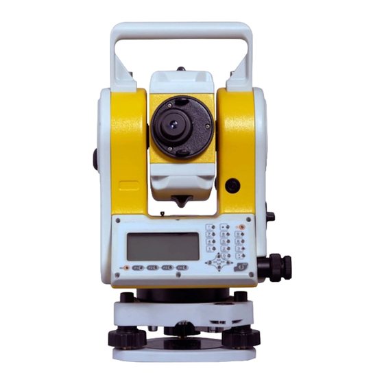
Page 17: Basic Functions
All manuals and user guides at all-guides.com 3. 3. 3. 3. Basic Basic Basic Functions Functions Basic Functions Functions 3 3 3 3 .1 .1 .1 .1 Nomenclature Nomenclature Nomenclature Nomenclature Optical sight Handle Objective Vertical motion clamp Plate level Vertical tangent screw Screen... - Page 18 All manuals and user guides at all-guides.com Handle screw Focusing knob Eyepiece Horizontal motion clamp Battery Horizontal tangent screw - 14 -...
-
Page 19: Power On/Off
All manuals and user guides at all-guides.com Basic Basic Operation Operation 3.2 Basic Basic Key Key Operation Operation Keys Description F1~F4 Select the functions matching the softkeys 1.Input number when numeric input 2.Input characters when alphabetic input . Input a decimal point Power Power on/off ±... - Page 20 All manuals and user guides at all-guides.com Note: 1 1 1 1 .."Power" indicate 2. 2. 2. 2. Basic measurement is composed of angle and dist and coordinate measurement mode Display Display 3.3 Display Display The LCD could display 6 lines with 24 characters per line. In measurement mode, it displays some common information in above 5 lines and displays soft functions in the last line.
- Page 21 All manuals and user guides at all-guides.com 92°18′22″ HR: 187°07′15″ Angle mode/basic measurement mode Save Set0 SetA P1/2 --Surveying-- ▲ 1.Select file [DIST] [ANG] 2.STA Setting 3.Orientation by Coordinates Dist mode/basic measurement mode 4.Orientation by angle ▼ 5.Sequence of Surveying Vz: 92°18′22″...
- Page 22 All manuals and user guides at all-guides.com Power Power On/Off On/Off 3.5 Power Power On/Off On/Off I. I. I. I.Power on 1. 1. 1. 1. Confirm the instrument is leveling, press the red [POWER]. 92°18′22" 2. 2. 2. 2. Release [POWER], 187°07′15"...
- Page 23 All manuals and user guides at all-guides.com How to to to to Input Input Input Number Number Alphabet Alphabet 3.6 How Input Number Number and and Alphabet Alphabet All Number and alphabet inputing must be carried out in a dialog box.for example, input point name SUN1A and STN -123.456 in "Setup station"...
-
Page 24: How To Configure
All manuals and user guides at all-guides.com 7. 7. 7. 7. Press [F3], switch into Alphabet input mode. 8. 8. 8. 8. press [1],'SUN1A' will present in input box. 9. 9. 9. 9. press [F4],the cerat will shift into STN input box, because the STN coordinate is Number attribute, the prompt "Alph."... - Page 25 All manuals and user guides at all-guides.com 3. 3. 3. 3. Laser Press [F3],to switch on or switch off the laser direction. 4. 4. 4. 4. Reflecting object Press [ ◀ ] , the EDM mode will be switched between "prism", "no prism"...
- Page 26 All manuals and user guides at all-guides.com Able 3-1 List of measurement condition setting Item Options 1.Units DMS*/GON/MIL; Meter*/feet/feetinch; ℃*/℉; hPa*/mmHg; 2.Type of feet InterFeet*/US Feet 3.HA display HAR*/HAL 4.VA display Zenith*/Horizon 0/V90(+/-)/slope 5.EDM mode Single*/repeat/Continue/Track 6.Min Readout(angle) 1"*/5"/10" 7.K option(earth curvature) 0*/0.14/0.20 8.Serial port option 2400/4800/9600/19200/38400/57600/11...
-
Page 27: Angle Measurement
All manuals and user guides at all-guides.com 4. 4. 4. 4. Angle Angle Angle Measurement Measurement Angle Measurement Measurement Measure Measure Measure a a a a Horizontal Horizontal Horizontal Angle Angle Angle of of of of Two Points Points 4.1 Measure Horizontal Angle Two Points Points... - Page 28 All manuals and user guides at all-guides.com The range and format of the input value: 92°18’22" 0 ~ 399..9999 gon: 123°00’05" degree: 359.5959 mil: 0 ~ 6399..999 Hold L/R V mode P2/2 3.
- Page 29 All manuals and user guides at all-guides.com 【Procedure Procedure Procedure distance distance measurement measurement Procedure of of distance distance measurement measurement】 1. 1. 1. 1. Aim at the target. Press 92°18’22" F2: [Meas] at P1 in the 187°07’15" measure mode. Press F1: [Save] will start measuring and save the Save Meas...
- Page 30 All manuals and user guides at all-guides.com wipe it with your special cloth (in your carrring case) before putting away. ◆If an object with a high reflective factor (metal, white surface) exists between the instrument and the target when measuring, the accuracy of the measured results will be affected.
- Page 31 All manuals and user guides at all-guides.com Input Input Occupied Occupied Point Point Data Data 6.1 Input Input the the Occupied Occupied Point Point Data Data 【Procedure Procedure Procedure Procedure of of inputting inputting inputting inputting occupied occupied occupied occupied point point point point data...
- Page 32 All manuals and user guides at all-guides.com press F4:[List] browse the coordinate file Set bss Save record? >BSS: and find out the point that Code ENT-->save you need. Press F3:[Info.] T.H.: 1.800 ESC-->No * file list Input Info. List information of the station if you have got the point.
- Page 33 All manuals and user guides at all-guides.com shown as the picture on the left. 2. 2. 2. 2. Press F4: [List] the list of Pt.(B.COO) 1/15 A001:100.0 100.0 existed coordinate swill be A002:100.0 100.0 got; If the point name is A003:100.0 100.0 error then system prompt A004:100.0 100.0...
- Page 34 All manuals and user guides at all-guides.com Azimuth Instrument Station Angle see "§6.1 Input the occupied point data". NOTE: NOTE: NOTE: NOTE: ◆ You can input the azimuth angle directly in angle measurement mode. Coordinate Coordinate Measurement Measurement 6.3 3D 3D Coordinate Coordinate Measurement Measurement...
-
Page 35: Input The Occupied Point Data
All manuals and user guides at all-guides.com Zenith angle Target Target (N-E-Z) N0-E0-Z0 Azimuth angle 【Procedure Procedure Procedure coordinates coordinates measurement measurement Procedure of of 3D 3D coordinates coordinates measurement measurement】 1. 1. 1. 1. Aim at the target point. 2. - Page 36 All manuals and user guides at all-guides.com is "Cont", "Rept" or "Track". 6. 6. 6. 6. It will display the distance and coordinate information after clicking the "CORD" key again in the "CORD" mode. See the picture above: 7. 7. 7. 7. Stake Stake Stake Measurement...
- Page 37 All manuals and user guides at all-guides.com ◆EDM settings could be set in this mode. 7 7 7 7 ..1 1 1 1 Distance Distance Distance Distance Setout Setout Setout Setout The point to be found based on the horizontal angle from the reference direction and the distance from the instrument station.
- Page 38 All manuals and user guides at all-guides.com Stack-out by distance B.S. Clear Mode Enter Stack-out by distance B.S. Clear Mode Enter 3. 3. 3. 3. Press F2: [Meas] to start EDM, when the error is less than 0.002mm then the 92°18’...
-
Page 39: Coordinate Measurement
All manuals and user guides at all-guides.com Distan Back sight station Point to be Setout Instrument Angle station 【Procedure Procedure Procedure coordinate coordinate Setout Setout measurement measurement Procedure of of coordinate coordinate Setout Setout measurement measurement】 ---Menu--- 1. 1. 1. 1. Press [MENU] in the 1.Surveying ▲... - Page 40 All manuals and user guides at all-guides.com 4. 4. 4. 4. If you can remember the point then you input the point name, else you can Pt.name 1001 press directly [ENT]. Alph. Clear Pt.(B.coo)1/19 5. 5. 5. 5. The point list will 1A: 100.000 120.000 appear.
-
Page 41: Distance Setout
All manuals and user guides at all-guides.com 8. 8. 8. 8. Distance setout mode, 0°00’18" we expect that dHR and dHR: -50°11’22" dHD tend to zero. dHD: Meas Mode T.H Next 9. 9. 9. 9. Coordinate setout mode, 0°00’18" dHR: -50°11’22"... - Page 42 All manuals and user guides at all-guides.com … NOTE: NOTE: NOTE: NOTE: ◆The number of points: 3 ~ 20. ◆Make sure these points must be measured or listed clockwise or anticlockwise, or mistake will result. Area Area Calculation Calculation Measured Measured Data Data...
- Page 43 All manuals and user guides at all-guides.com 2. 2. 2. 2. Area measurement Survey area Pt01: 100.000 120.000 interface is shown as the picture on the left. You can press F1: [Input] a point or call an existing point. Input Meas Del Point/Area 3.
-
Page 44: Offset Measurement
All manuals and user guides at all-guides.com 6. 6. 6. 6. Press F4: [Enter] Survey area Pt01: 100.000 120.000 accept the measured point Pt02: 100.000 100.000 coordinate. Pt03: 200.000 290.000 7 7 7 7 ..After the numbers of Input Meas DEL Calc points is more than 2, the calculation is possible.Then... - Page 45 All manuals and user guides at all-guides.com to measure (target point) by installing the target at a location (offset point) a little distance from the target point and measuring the distance and angle from the surveying point to the offset point. The target point could be found in the following four ways.
- Page 46 All manuals and user guides at all-guides.com 【Procedure Procedure Procedure dist dist dist1 1 1 1 offset offset offset m m m easurement easurement easurement Procedure of of dist offset m easurement】 1. 1. 1. 1. Input the known offset distance.
- Page 47 All manuals and user guides at all-guides.com 【Procedure Procedure Procedure dist dist dist2 2 2 2 offset offset offset m m m easurement easurement easurement Procedure of of dist offset m easurement】 1. 1. 1. 1. Input the known offset Offset(dist2)-Distance Offset Distance: distance.
- Page 48 All manuals and user guides at all-guides.com Angle Angle Offset Offset Measurement Measurement 9.2 Angle Angle Offset Offset Measurement Measurement Sometimes we need to measure a coordinate of a point such as A1 whose position cannot place a prism. Assume that we know that the horizontal distance from CI to A1 and the distance from CI to prism are equal.
-
Page 49: Angle Offset Measurement
All manuals and user guides at all-guides.com 【Procedure Procedure Procedure angle angle offset offset measurement measurement Procedure of of angle angle offset offset measurement measurement】 Offset 1. 1. 1. 1. Select the function of 1.Offset(Angle) ▲ angle offset measurement. 2.Offset(Dist1) 3.Offset(Dist2) 2. - Page 50 All manuals and user guides at all-guides.com Plane Plane Offset Offset Measurement Measurement 9.3 Plane Plane Offset Offset Measurement Measurement Sometimes we wish to obtain the coordinate of some points where we cannot measure directly distance. Fortunately, we can measure the distances of another points, and all these points are in a plane.
-
Page 51: Plane Offset Measurement
All manuals and user guides at all-guides.com 【Procedure Procedure Procedure Plane Plane offset offset measurement measurement Procedure of of Plane Plane offset offset measurement measurement】 1. 1. 1. 1. Press F1:[Meas], start Offset(plane)-Pt.1 1°55’42" EDM to obtain the Azimuth 4.847 m and distance of P1. - Page 52 All manuals and user guides at all-guides.com Column Column Offset Offset Measurement Measurement 9.4 Column Column Offset Offset Measurement Measurement Sometimes we wish to obtain the coordinate of column center where we cannot find out directly. Fortunately, we can measure the distances of another points on the column.
- Page 53 All manuals and user guides at all-guides.com 2. 2. 2. 2. Aim at the left edge of Offset(Column)-left edge 0°14’19" the column, get its data. 4.836 m 4.832 0.193 Enter Offset(Column)-Rightedge 3°35’23" 4.836 m 3. 3. 3. 3. Aim at the left edge of 4.832 the column, get its data.
- Page 54 All manuals and user guides at all-guides.com 10. MLM MLM is used to directly measure slope distance, horizontal distance and the height difference from one base point to other points without moving the instrument. MLM have two modes, one is MLM (A-B, A-C), the other is MLM (A-B, B-C), and the two modes are shown as follow.
-
Page 55: Mlm
All manuals and user guides at all-guides.com 【Procedure Procedure Procedure measurement measurement Procedure of of MLM MLM measurement measurement】 [Menu]—>4.Program—>2.MLM Grid scale 1. 1. 1. 1. If considering the effect 1.Considering Grid scale 2.Ignore Grid scale of grid scale you should select menu item 1, else you should select menu item 2. - Page 56 All manuals and user guides at all-guides.com 3. 3. 3. 3. Press F1: [Meas] to start MLM(A-B,A-C)-Step 1 EDM then you can obtain 88°18’22" the coordinates of the base 1°46’31" point, or Press F3: [Coord] then call Meas T.H coord Mode existing coordinate from current coordinate file.
-
Page 57: Height Measurement (Rem)
All manuals and user guides at all-guides.com Height Height measurement measurement (REM) (REM) 11. Height Height measurement measurement (REM) (REM) REM is a function used to measure the coordinate and height to a point where a target (prism) cannot be directly installed such as power lines, overhead cables or bridges, etc. - Page 58 All manuals and user guides at all-guides.com Height of ins.&prism 2. 2. 2. 2. Setting height I.H: 1.500 instrument and the height T.H: 1.000 of prism. B.S Clear Save Enter 3. 3. 3. 3. Press F1: [Meas] to start EDM then you can obtain REM-Prism 88°18’22"...
- Page 59 All manuals and user guides at all-guides.com 【Procedure TH) ) ) ) 】 Procedure Procedure REM( REM( Without Without Procedure of of REM( REM(Without Without TH [Menu]—>4.Program—>1.REM 1. 1. 1. 1. Select menu item 2 when -REM-- 1.With TH ▲ you need the difference of 2.Without TH height between any two...
- Page 60 All manuals and user guides at all-guides.com Intersection Intersection 12. Intersection Intersection Intersection program is used to determine the coordinates of an instrument station (unknown) by measuring several known points. Coordinate data in memory could be read. Input Coordinates of known points: Xi, Yi, Zi Measured HA: Hi Measured VA: Vi Measured distance: Di...
-
Page 61: Intersection-Pt.1
All manuals and user guides at all-guides.com NOTE: NOTE: NOTE: NOTE: ◆ All N, E, Z value or only Z value of the occupied point is calculated by measuring known points. ◆Coordinate intersection measurement overwrite the N, E, Z data of the instrument station. ◆Inputted known coordinate data and calculated data could be recorded in the current coodinate file. - Page 62 All manuals and user guides at all-guides.com 3. 3. 3. 3. If you have selected the Intersection-Pt.1 distance mode then you need 80°00′13″ to press F4: [Dist] starting 340°56′50″ 4.890 EDM and obtaining the slope T.H: 1.000m distance. After measuring Next distance, you press F1: [Next] to measure next point.
- Page 63 All manuals and user guides at all-guides.com 12.2 12.2 Elevation Elevation Intersection Intersection Intersection— — — — Coor Coor Coor Coord d d d .Z .Z .Z .Z 12.2 12.2 Elevation Elevation Intersection Only Z (elevation) of an instrument station is dertermined by this measurement.
- Page 64 All manuals and user guides at all-guides.com Coord.Z-Pt.1 1°46’36" 4.897m 4. 4. 4. 4. One or more known point 4.837 0.767 can calculate the coordinate Next Mode calc Coord.Z-Pt.2 5. 5. 5. 5. Another known point will 23°42’19" be measured. 6.408m 6.362 0.767...
- Page 65 All manuals and user guides at all-guides.com 12.3 12.3 Precautions Precautions When When Performing Performing Intersection Intersection 12.3 12.3 Precautions Precautions When When Performing Performing Intersection Intersection In some cases, it is impossible to calculate the coordinates of occupied point if the unknown point and three or more known points are arranged on the edge of a single circle.
-
Page 66: Point Projection
All manuals and user guides at all-guides.com (2)Measure one more known point which is not on the circle. (3)Perform a distance measurement on at least one of the three points. Point Projection 13. Point Point Point Projection Projection Projection Point projection is used for projecting a point to an established baseline. -
Page 67: Define Baseline
All manuals and user guides at all-guides.com 13.1 13.1 Define Define Baseline Baseline 13.1 13.1 Define Define Baseline Baseline 【Procedure Procedure Procedure Procedure of of defining defining defining defining baseline baseline baseline baseline】 [MENU]—>4.Program—>5.Project Projection 1. 1. 1. 1. Select the menu item 2 to 1.Height of Ins.&Targe ▲... -
Page 68: Inverse
All manuals and user guides at all-guides.com 【Procedure Procedure Procedure Procedure of of point point point point projection projection projection projection】 Projection 1. 1. 1. 1. Select the menu item 3 to 1.Height of Ins.&Targe ▲ 2.Setup Baseline define a baseline. 3.project 2. -
Page 69: Roadway
All manuals and user guides at all-guides.com Input: Output: Coordiante of start point: N0, E0, Z0 Distance: D Coordinate of end point: N1, E1, Z1 Azimuth: AZ End point Start point This function can be implented in MLM MLM when all coordinates is called from the coordinates file. - Page 70 All manuals and user guides at all-guides.com A roadway can be described as a Horizontal curve and a Vertical curve. We describe a horizontal element by line、circle、 spiral and point of intersection, these shape have some attribute as follow: Length of line Azimuth Line Length of arc...
- Page 71 All manuals and user guides at all-guides.com 15.1 15.1 Define Define Horizontal Horizontal Curve Curve Curve of of of of Roadway Roadway Roadway 15.1 15.1 Define Define the the Horizontal Horizontal Curve Roadway 【Procedure Procedure Procedure Procedure of of defining defining defining defining Horizontal...
- Page 72 All manuals and user guides at all-guides.com 5. 5. 5. 5. For example,input a Define(H)_Circle circle whose radius is 100 and length is 20. Radius: Length: Clear Enter 6. 6. 6. 6. Calculate the mileage Define(H)_03 and azimuth of the fan-out Mileage: 170.000 point.
- Page 73 All manuals and user guides at all-guides.com 9. 9. 9. 9. Max number of element is 20. Press [ENT] to pop List of H curve 01Start: 100 up the list box of all 02Line: inputed element. Press 03Circle: 170 04Spline: 215 F1:[Save] save element...
- Page 74 All manuals and user guides at all-guides.com 3. 3. 3. 3. Input another I.P. one N:(Pt.1) by one.press [ENT] to accept a dialog box. Radius: 4. 4. 4. 4. Press [ESC] to stop B.S Clear Enter inputing, and then pop up a list box of I.P.
-
Page 75: Roadway Setout
All manuals and user guides at all-guides.com mileage 508.306 1000.48 altitude 324.325 329.247 325.689 length 84.56 52.806 The input method of defining vertical curve is just same as the see 【 Procedure Procedure defining Procedure Procedure defining defining defining horizontal I.P., Horizontal Horizontal... - Page 76 All manuals and user guides at all-guides.com Stake-out road 1.Select file ▲ 2.STA Setting 3.Orientation by Coordi 4.Stake out The figure for road setout is shown as follow : center Left dH(-) Right dH(-) Right distance Left distance Space between stake 【Procedure Procedure...
- Page 77 All manuals and user guides at all-guides.com parameter 2/2 2. 2. 2. 2. Input left distance, right Left dist Right dist distance etc. Left dV: Right dV: B.S. Clear Enter 3. 3. 3. 3.Use [ ▲ ][ ▼ ]to set the Roadway-Center mile on the stake that you Mileage:...
-
Page 78: Fileman
All manuals and user guides at all-guides.com 24°32’ 20" 6. 6. 6. 6.The mathod is same as dHR: -60°16’00" "§7. Setout Measurement" dHD: Press F4: [Next] to setout the next stake. Meas Mode T.H Next Fileman 16. Fileman Fileman Fileman 16.1 File management... - Page 79 All manuals and user guides at all-guides.com SVY.COD ▲ 1. 1. 1. 1. The file operation B.MEA dialog box is shown as B.COO the picture of the left. BAA.MEA V.LSH ▼ New Del Browse Select 2. 2. 2. 2. Press F1: [New] to create a new file.
- Page 80 All manuals and user guides at all-guides.com 4. 4. 4. 4. Press F3: [Browse] to Pt.name DA browse the highlight file. If Code: B the file is coordinate file or T.H. 1.500 HA: 24°32’ 20" measurement file then the VA: 89°12’30" record is shown as the Begin PgUp PgDn End picture...
- Page 81 All manuals and user guides at all-guides.com 6. 6. 6. 6. Measurement file can be exported from the RS232; Baudrate: 115200 Filename: A.MEA The operation is same as the No: 33 importing. Fast Slow File Export 7. 7. 7. 7. Sometimes, many files --Fileman-- 1.Fileman ▲...
- Page 82 All manuals and user guides at all-guides.com 16.2 16.2 Parameters Parameters calibration calibration menu menu 16.2 16.2 Parameters Parameters calibration calibration menu menu The option in the parameters calibration are as follows: Calibrate 1.Calibrate Index ▲ 2.Calibrate compensator 3.Add const 4.Mul.Const ▼...
- Page 83 All manuals and user guides at all-guides.com switch off the compensator, and the index difference is small. Process as follows: set the instrument as shown, collimator is above, it is convenient to use feet spiral C to adjust the slant state of instrument.
- Page 84 All manuals and user guides at all-guides.com on the target as the collimator directs ,record the current vertical angle V1; Set the vertical angle as V1-3 ′ by slow motion screw, adjust the angle spiral C to focus on target accurately , stay for a stable reading , press "confirm"...
-
Page 85: Grid Factor
All manuals and user guides at all-guides.com 1) elevation factor Elevation factor = R / (R + elevation) R: the earth's average curvature radius Elevation: Elevation above the mean sea level 2) scale factor Scale factor: the measurement station scale factor 3) grid factor Grid factor = elevation factor ×... -
Page 86: Level Tube
All manuals and user guides at all-guides.com so you must input again. Use "ESC button" to escape without saving. 1 1 1 1 7. 7. 7. 7. Checkout Checkout Checkout calibration calibration Checkout and and calibration calibration The instrument is under strict test and calibration, the quality is accord with the standard demand. -
Page 87: Circular Level
All manuals and user guides at all-guides.com 3. 3. 3. 3. Turn the instrument for 90 ° , use the third foot screw to adjust the bubble to the center. · Repeat the steps of checkout and calibration until the bubble in the center in every directions . - Page 88 All manuals and user guides at all-guides.com 3. 3. 3. 3. If A moves along the vertical line of the crosshair, but A point is still in the vertical line, as the left picture, the crosshair doesn't need to calibrate. If A point deviate from vertical line center, as the right pictured, the crosshair is slant, so need to calibrate the reticle.
-
Page 89: (2 C)
All manuals and user guides at all-guides.com Set screw eyepiece 1 1 1 1 7 7 7 7 .4 .4 .4 .4 The verticality verticality verticality of of of of collimation collimation collimation axis axis horizontal horizontal The verticality collimation axis axis and and horizontal horizontal... - Page 90 All manuals and user guides at all-guides.com horizontal angle to the right reading which has eliminated the R + C = 190°13 '40 "-15 "= 190°13' 25". 2. 2. 2. 2. Take down the reticle bed cover between the telescope eyepiece and focusing handwheel, adjust the calibration screw of the crosshair on the left and right.
- Page 91 All manuals and user guides at all-guides.com instrument and any of the foot screw. 2. 2. 2. 2. The vertical plate index change to zero after switching on, tighten the vertical brake handwheel, the instrument display the current telescope vertical Angle. 3.
- Page 92 All manuals and user guides at all-guides.com right. 3. 3. 3. 3. If the vertical zenith angle is 0°, then i = (L + R-360°) / 2, if the vertical Angle level is 0 . Then i = (L + R-180°) / 2 or (L + R-540 °) / 2.
- Page 93 All manuals and user guides at all-guides.com 4. 4. 4. 4. Rotate alidade, every turn of 90°, observe the contact ratio of the optical plummet and cross center . 5. 5. 5. 5. When rotate the alidade, the center of the optical plummet always coincide with the cross center, there is no need to calibrate.Otherwise you should calibrate as the following methods.
- Page 94 All manuals and user guides at all-guides.com requirements. 6. 6. 6. 6. With the laser plummet, unbolt the laser cover, using 1 # hex wrench to adjust the three screws, fasten one side and loosen the other side, and adjust the laser flare to point O. 7.
- Page 95 All manuals and user guides at all-guides.com changing after strict inspection , you need to calibrate it, set the instrument additive constant according to the comprehensive constant K value . Such as: the K has been measured as -5 according to the method above, and the original instrument constant is -20, so the new value should be set as -20-(5) =-15;...
- Page 96 All manuals and user guides at all-guides.com the emission photoelectricity axis center, if they coincide on the whole we can say it qualified. ·Calibration Calibration Calibration Calibration If the telescope crosshair center deviate from emission photoelectricity axis center largely, send it to professional repair and calibration department.
-
Page 97: Specifications
All manuals and user guides at all-guides.com eyes cann′t see laser point through the telescope, you can see the offset between the red laser point and the reflector crosshair center, you can observe this above the telescope or at the side face of reflector. - Page 98 All manuals and user guides at all-guides.com @white board reflectivity 18% Mini-reading Fine mode 1mm Accuracy ±(2mm+2ppm·D)@prism ; ±(5mm+3ppm· D)@no prism Measurement time Fine mode: 2 sec @single mode; 1.2sec @continue mode Tracking mode: 0.5 sec Temperature unit ºC/ºF, selectable Pressure unit hPa/mmHg, selectable Temperature input range -20ºC to +60ºC (1ºC steps) Refraction and earth curvature correction OFF/0.14/0.2,...
- Page 99 All manuals and user guides at all-guides.com Internal memory 20000 points Data Data communication communication Data Data communication communication I/O RS-232C Power Power Power Power Battery Li-ion Rechargeable battery Voltage 7.4V DC Continuous operation tine ~9 hrs Distance & angle, ~24 hrs Angle only Chargers 100V to 240V 50/60Hz Charging time (at +20℃) Approx.
- Page 100 All manuals and user guides at all-guides.com 1 1 1 1 9 9 9 9 ..Prompt Prompt Prompt Warning Warning Error Error Messages Messages Prompt,Warning Warning and and Error Error Messages Messages " " " " Tilt Tilt Tilt Over"...
- Page 101 All manuals and user guides at all-guides.com "Select "Select coor.file" coor.file" coor.file"— — — — assign assign assign assign a a a a coordinates coordinates coordinates file file "Select "Select coor.file" coordinates file file " " " " Overtop" Overtop" Overtop"—...
- Page 102 All manuals and user guides at all-guides.com "Open "Open error" error" error"— — — — cannot cannot cannot open open file file "Open "Open error" cannot open open file file "T.H. overtop" overtop"— — — — the height height of of of of the prism prism is is is is out out of of of of range...
- Page 103 All manuals and user guides at all-guides.com "Max "Max elements elements should should should be be be be less less less than than 20!" 20!" 20!"— — — — there there there are 20 20 20 20 or or or or "Max "Max elements elements should...
- Page 104 Surveying Instrument to be free from manufacturing defects in materials and workmanship. For claims to be made under this warranty the instrument must be inspected by Hi-Target and the defect must be proven to Hi-Target’s satisfaction. At the time that it is proven to the Hi-Target’s satisfaction that the instrument is defective, it shall be repaired or replaced, at the Hi-Target’s option and returned to the original purchaser at no...
- Page 105 Hi-Target determines that additional repair services are required and not covered under this warranty, Hi-Target shall notify the Buyer of such repair charges and proceed only after authorization has been received. C. This warranty does not apply to instruments damaged in transit to or from Hi-Target Instrument or any authorized repair center.
Need help?
Do you have a question about the ZTS Series and is the answer not in the manual?
Questions and answers