Table of Contents
Advertisement
Quick Links
Advertisement
Chapters
Table of Contents

Subscribe to Our Youtube Channel
Related Manuals for Hi-Target HTS-420R


Summary of Contents for Hi-Target HTS-420R
- Page 2 Total Station Manual Preface Thanks a lot for purchasing our total station! This manual is your good helper, please read it carefully before using the instrumentand keep it safely. Product affirms: In order to get the best service from our company, please feedback your instruments’ versionincludingnumber, purchasing date and your suggestions to us after the purchasing of the product.
- Page 3 Total Station Manual Features: Rich Feature: Our Total Station is equipped with a wealth of measurement applications including data storage, parameter settings and other functions for a 1. Absolute coded dial With absolute digital dial, instrumentscan be measureddirectlywhen it powers on. The measured azimuth angle result will not be lost even when the instrument shut off.
- Page 4 Total Station Manual NOTE: Avoid look directly into the sun with the eyepiece when measuring. Recommended to use solar filter to reduce the impact 1. Avoid extreme temperature when storing equipment and sudden changes in temperature when using the instrument. 2.
- Page 5 Total Station Manual Security Guide Pay attention to the following safety matters when you use the laser ranging free of prism. Warning: Total station fit out laser level 3R/Ⅲa which is recognized by the loge, which is above: the verticallocking screw saying: “3A laser product ”.This product belongs to Class 3R levellaser .According to the following standards IEC 60825-1:2001Class 3R/Ⅲa laser product can reachfive times of emission limits of the Class 2/Ⅱ...
- Page 6 Total Station Manual F: properly store and safekeep the laser products when they it is not used, unauthenticated personals are not allowed using it. G: Do not point laser beams at surfaces such as plane mirror, metal surface, window, especially the surface of plane mirror and concave mirror. Harmful Distance is the maximum distance from the starting point of the laser beams to where people are right safe.The built-in harmful idstance of the Class 3R/ Ⅲa laser is 1000m(3300ft) and the laser intensity will reduce to that of Class 1...
-
Page 7: Table Of Contents
Total Station Manual CONTENTS 1. Name and function of each part ................10 1. Name ......................10 2. Keys Functions and information display ............12 2. Preparation before measurement ................ 13 1. Unpack and store instrument ................ 13 2. Setting up the instrument ................13 3. - Page 8 Total Station Manual 6. Free Coding ....................52 7. Laser Pointer ....................52 8. Light ........................ 52 9. Unit Setting ....................53 Main Setting .................... 53 EDM Tracking ..................54 5. Applications ......................55 1. Setting the Job ....................55 Create a new Job ................
- Page 9 Total Station Manual 11.4 Bearing-Distance Intersection ............112 11.5 Distance-Distance Intersection ............115 11.6 Line-Line Intersection ..............118 11.7 Distance-Offset................120 11.8 Set Point ..................122 11.9 Extension ..................124 Road ...................... 126 12.1 Road Manage ................. 126 12.2 Horizontal curve definition ............127 12.3 Vertical curve definition ..............
- Page 10 Total Station Manual Adjust Tilt X ..................170 Instrument constant setting ............171 Factory setting ................171 2. System infomation ..................172 View System Information ............... 172 Set System Date ................172 Set System Time ................172 Firmware Upgrade ................. 173 3.
-
Page 11: Name And Function Of Eachpart
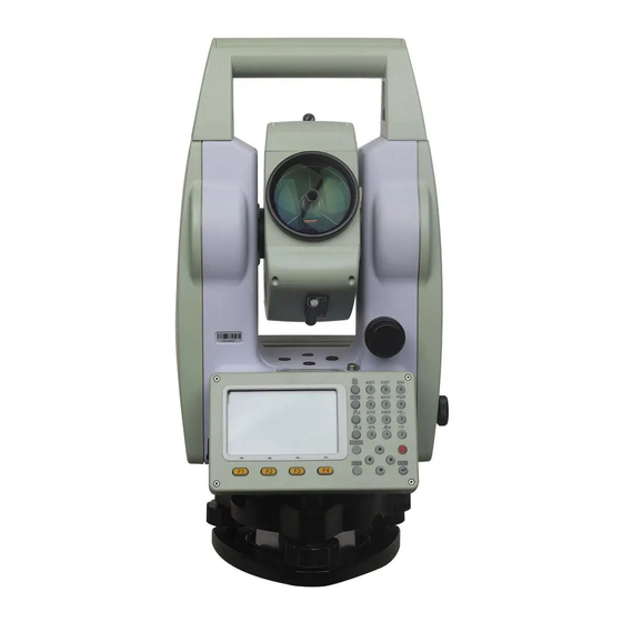
Total Station Manual 1. Name and function of eachpart Name - 10 -... - Page 12 Total Station Manual - 11 -...
-
Page 13: Keys Functions And Information Display
Total Station Manual Keys Functions and information display Function Power ON/ Power OFF. MEAS Trigger key, depends on setting, maybe disting& save, disting or none. Cancel or exit. Confirm or commit editing. Switch pages Hot key to enter function menu in measuring interface. User defined function key 1. -
Page 14: Preparation Before Measurement
Total Station Manual 2. Preparation before measurement Unpack and store instrument Unpack Put down the box gently and turn up the cover then turn on the lock, open the cover and take out the instrument. Deposit Cover up the telescope mirror and make the vertical motion of alidade upwards then put the instrument horizontally (keep the objective upwards) into box. - Page 15 Total Station Manual ②Rotate instrument 90°by vertical axis, then use foot screw C to center the bubble. ③Repeatsteps above until the bubble is at the same place in all directions. 2. Centering by centering tool ( optional or laser ) 1) Set up a tripod Extend a tripod to the appropriate height make sure the legs are spaced at equal intervals and the head is approximately level .Set the tripod so that the head is...
-
Page 16: About The Battery
Total Station Manual instrument aim at station accurately. Tighten the center connection screw and leveling instrument accurately again. This operation should be repeated till the plumb aims at station accurately. About the battery Mounting the battery ☆Fully charge the battery before measurement. ☆Cut off the power before removing the battery. -
Page 17: Reflecting Prism
Total Station Manual Charging range from 0°~±45℃. Abnormal responds of instrument occurs over this range. Rechargeable for300—500 times, it may shorten Service time of the battery completely. Charge the battery once a month no matter if it is used to prolong its longevity. Reflecting prism When using a prism mode for measuring distance, reflection prism should be placed where the target is. -
Page 18: Input Characters
Total Station Manual Input box: Each digit key defines 3 letters and 1 number. Depends on the properties of input box, input process varies. Number input box: In number input box, user can only input numbers, include “1-9”,“.”, “-+”. Number will appear in box when user presses the key. -
Page 19: Delete Characters
Total Station Manual [Q-Survey] 1/3 ○ 2 Press key 1, key 2, key 123| T.H. 1.500 m 3. Then press key F4, Code active text input [1],[2],[3],[F4] 13°29′59″ 90°59′23″ mode.Icon should 10.044 m appear in right bottom B.S. Clear Digit screen. -
Page 20: Point Search
Total Station Manual [Q-Survey] 1/3 PT|001 T.H. 1.500 m Code ○ [F1] 2 Press key F1(Delete). 13°29′59″ 90°59′23″ 10.044 m B.S. Clear Alpha [Q-Survey] 1/3 PT001 T.H. 1.500 m ○ 3 Press key ENT to confirm Code [ENT] 13°29′59″ input. Press Key ESC to [ESC] 90°59′23″... - Page 21 Total Station Manual ○ searching result [Find Pt.] Station window, using arrow key ↑ ↑ ↓ Station Meas. PT [F4] Meas. PT ↓ to move cursor to select Fix Pt. [ENT] point number. Press key F4 or View Coord. ENT to conirm selecting. Soft keys introduction: [View] Show the coordinate of selected point.
- Page 22 Total Station Manual [Input Coord.] DEFAULT ○ 4 Input point number and N, 3.012 m E, Z values, by pressing ENT to [ENT] 15.012 m 4.215| move cursor to next input box. B.S. Clear Alpha ○ 5 After all values finishing [F4] input, pressing key F4 to save the point to the job.
-
Page 23: Wildcard Search
Total Station Manual [Find Pt.] Fix Pt. ○ 6 Press key F4 to search the [F4] point in the selected job. View Coord. ※ [F2](Zero):Set N, E, Z to 0. [F3](Coord.):Input point manually. [OK] Commit selected point. Wildcard search The wildcard search is indicated by a “*”. The asterisk is a place holder for any following sequence of characters. -
Page 24: Q-Survey
Total Station Manual 3. Q-Survey Notes in the distance measurement After the placement of instrumentand turned on the power, total station is ready, can start measuring. In measurement display, user can call the function of set key, the functionkeys and hotkey. The show is an example. - Page 25 Total Station Manual When start the distance measurement, EDM will measure distance for the object in the light path.If there are temporary obstacles in the light path (such as by car, or the heavy rain, snow, or filled with fog), the distance measured by EDM is the distance to the nearest obstacle.
-
Page 26: Edm Setting
Total Station Manual EDM Setting Set the mode of EDM Select the mode of distance measurement,there are 6 modes : Single,Repeat,Tracking,3 Times,4 Times,5 Times. Steps Display [Q-Survey] 1/3 ○ 1 Press[F4](↓)and show the T.H. 1.500 m Code second soft [F4] 13°29′59″... - Page 27 Total Station Manual refer to “Technical Parameters”. Steps Display [EDM Setting] ○ After entering to the EDM Mode: Single interface of EDM Setting,using Reflector: Prism ↓ P.C. -30.0 mm the direction of ↓ to move the cursor to the setting item ATOMS Pointer of Reflector.
-
Page 28: Atomosphere Setting
Total Station Manual Steps Display [EDM Setting] ○ 1 After entering to the EDM Mode: Single interface of EDM Setting,using Reflector: Prism ↓ P.C. 30.0 mm the direction of ↓ to move the cursor to the setting item ATOMS Pointer of P.C. - Page 29 Total Station Manual Steps Display [EDM Setting] ○ 1 After entering to the Single EDM Mode: interface of EDM Setting, Reflector: Prism [F1] P.C. 30.0 mm press [F1] (Atoms) to enter the interface of Atomspheric Data. ATOMS Pointer ○ Interface displays current setting, using the [Atomspheric Data]...
- Page 30 Total Station Manual press:1013hPa temperature:20℃ If the atmospheric correction is not required, please set PPM to zero. Steps Display [EDM Setting] ○ After entering to the Single EDM Mode: interface of EDM Setting. Reflector: Prism [F1] P.C. 30.0 mm Press [F1] (Atoms) to enter the interface of Atomspheric Data.
-
Page 31: Grid Factor Setting
Total Station Manual ○ 5 After finishing setting, [EDM Setting] press [F4](OK) to save settins Single EDM Mode: back previous Reflector: Prism [F4] P.C. 30.0 mm menu.Then press the key of [F3] [F3](OK) to save the setting of EDM and back to the function ATOMS Pointer of measurement. - Page 32 Total Station Manual 2. The enter range of the average height above sea level: -9999.9999~9999.9999. The average altitude retained after the decimal point one, the default value is 0. Steps Display ○ [EDM Setting] 1 After entering to the Single EDM Mode: interface of EDM Setting,press Reflector:...
-
Page 33: Edm Signal
Total Station Manual EDM signal The function of signal is to display the intensity of signal received by total station.If the target is hard to be found or can’t see, using the function can achieve the best sighting accuracy. Steps Display ○... -
Page 34: Start Measurement
Total Station Manual Start measurement Q-Survey has 3 pages menu, including all measuring functions commonly used, such as angle measurement, distance measurement and coordinate measurement. As shown below: [Q-Survey] 1/3 [Q-Survey] 2/3 T.H. T.H. 1.500 m 1.500 m Code Code 13°29′59″... - Page 35 Total Station Manual ○ 2 Press [F2](Zero) , the Set HA=0? [F2] screen give a prompt to set HA as 0 or not. [Q-Survey] 1/3 ○ 3 Press [F4](Yes), the screen T.H. 1.500 m [F4] Code backs to Q-Survey and HA is 0°00′00″...
- Page 36 Total Station Manual to go back. [SetHA] 359°39′01″ If want other value of angle as Zero orientation angle,you need to enter the wanted [F4] B:Input angle value of angle and press [SetHA] [ENT],then press [F4](OK). Example: enter 121.2030 121°20′30″ (121°20′30″). Zero C:...
-
Page 37: Set Station And Instrument Height
Total Station Manual Set Station and instrument height After set the coordinate of station (the site of instrument) relatives to the origin, the instrument can calculate the coordinate of the location to your position (the site of prism). You can set station and the instrument height conveniently in the Q-Survey. Steps Display [Q-Survey] 1/3... -
Page 38: Measurement
Total Station Manual Measurement After all settings have been finished, you can start to measure. There are 3 pages to display the result of measurement, including all measurement data and you can press [PAGE] to view. Steps Display [Q-Survey] 1/3 ○... -
Page 39: Code
Total Station Manual Code The code contains the information about the recording points, in the process of post-processing, with the help of encoding function , you can process conveniently according to the specific group.The function of “File Manager” also contains the information of code. - Page 40 Total Station Manual Before REC:Record code data before recording the actual measurement data. After REC:Record code data following after the actual measurement data. Soft key of Code After starting the function of soft key (Code), Screen displays the following: [View Code] Code CODEA Note...
-
Page 41: Funtions
Total Station Manual 4. Funtions Bring the total station’s common functions and settings together, they can be used in the process of measurement conveniently. In the function of Q-Survey which in the Main menu or other interface of measuremen in the program,you can press [FNC] to enter the menu of Function The menu of Function has 4 pages, you can press 【PAGE】... -
Page 42: Offset
Total Station Manual [Function] ※ F1 Level X: 0'14" F2 Offset 【F1】 Y: -0'15" F3 NP/P F4 HT. Transfer Single ◆ Press [On] to open the compensator and press [Off] to close the compensator. ◆ Press [X Only] to open the compensator of X direction. ◆... -
Page 43: Cylinder Offset
Total Station Manual Steps Display [Function] ○ program F1 Level F2 Offset Q-Survey, press [FNC] to [F2] F3 NP/P open the menu of Function, next pressing [F2] to enter F4 HT. Transfer the program of Offset. [Dist. Offset] ○ Input offset data! 2 Input the values of Trav.OFS: 2.000 m... - Page 44 Total Station Manual angle that station point with cylinder in Hz Left and Hz Right, thus can measure the distance between cylinder and station. Steps Display [Function] ○ program F1 Level F2 Offset Q-Survey, press [FNC] to [F2] F3 NP/P enter the menu of Function, then pressing [F2] to enter F4 HT.
-
Page 45: Angel Offset
Total Station Manual Cylinder Offset-Result. [Cylinder Offset-Result] Note ○ 12.215 m 5 Display the result of 25.325 m cylinder offset. 0.000 m Radius : 8.125 m Done Angel Offset Instrument station Measured point Target point α1 The HA of the point P α2 The HA of the point C α2 α1... - Page 46 Total Station Manual [Dist. Offset] Input offset data! Trav.OFS: 2.000 m ○ LengthOFS: 1.000 m 2 Press [F3] to enter the [F3] HeightOFS: 0.000 m subprogram of Angel Offset. Mode Rec/Reset 偏置模式 : 偏置模式 : Reset Cylinder Angle [Angle Offst] T.H.
-
Page 47: Np/P Toggle
Total Station Manual NP/P Toggle Switch the mode of reflector quickly. (P is the mode of Prism and NP is the mode of Non-Prism) Set P! [Function] F1 Level F2 Offset 【F3】 F3 NP/P F4 HT. Transfer Set NP! Open the first page of Function Menu and press [F3] to switch the mode of reflector. Height Transfer The functions of HT. -
Page 48: [Function]
Total Station Manual Steps Display [Function] F1 Level F2 Offset F3 NP/P ○ F4 HT. Transfer 1 Press [F4] or [4] in the [F4] first page of [Function] to enter the function of [Height Transfer] 1 Height Transfer Select target and meas.! :... - Page 49 Total Station Manual ○ 3 Selcet the fixpoint and [Height Transfer] Select target and meas.! input the height of Prism. : Pt.1 numbers T.H. : 1.200 m : 2.500 m measured fixpoints are : displayed in the top right 偏置模式 : [F4] corner.
- Page 50 Total Station Manual ○ 4 After finishing setting [Height Transfer] 1 up the fixpoint, the height Select target and meas.! [F1] of fixpoint is displayed in : Pt.1 the screen and press [F1] T.H. : 1.200 m [F2] : 2.500 m (ALL)...
-
Page 51: Hidden Point
Total Station Manual Hidden Point The function of Hidden Point is using a specia hidden point measuring rod to measure the points which are not intervisible. P0 Instrument station P1 Hidden point R1 Prism 1 R2 Prism 2 d1 Distance between prism 1 and 2 d2 Rod length The length of measuring rod is known, by measuring the position information of... - Page 52 Total Station Manual [Rod Length] ○ 3 Inputting the correct Rod length : 3.000 m value of Rod length and R1-R2 1.000 m [F4] Error Limits: 0.001 m pressing [F4] to back to measure the first prism 偏置模式 : 偏置模式 : point.
-
Page 53: Free Coding
Total Station Manual [Hidden Point-Result] Note ○ 4.325 m 7 Display the result of 4.365 m hidden point measurement. 2.235 m 偏置模式 : Done Free Coding Please refer to “3. Q-Survey”→“3. Start Measurement”→“3.4 Code” Laser Pointer Open or close the laser fastly. [Function] F1 Hidden Point F2 Free Coding... -
Page 54: Unit Setting
Total Station Manual Unit Setting Set the common Unit fastly. Angle Unit : °′″ [Function] Dist. Unit : Meter F1 Unit Setting Temp. Unit : ℃ F2 Main Setting (01) Press. Unit : 【F1】 F3 EDM Tracking (02) Reset Open the third page of Function Menu and press [F1] to enter the interface of unit setting. -
Page 55: Edm Tracking
Total Station Manual 11. EDM Tracking Open or close the mode of EDM Tracking fastly. [Function] F1 Unit Setting F2 Main Setting (01) F3 EDM Tracking (02) EDM Tracking On! EDM Tracking Off! Open the thied page of Function Menu, press [F3] to open or close the mode of EDM tracking. -
Page 56: Applications
Total Station Manual 5. Applications Prepare setting before measuring: Before startingthe application, there are some preparations needed to set up. The Pre-Settingsscreenwill beshown after the user selects an application. User can select and set the content of the Pre-Settings menu successively. [Surveying] [*] F1 Set Job... - Page 57 Total Station Manual ○ 2 Press [F2](New) and then [Set Job] enter the Create a New Job DEFAULT screen. Operator: Press [F4](OK), the displayed [F1] Date 20150515 Time 14:10:20 job will be set as current job and then back to Pre-Settings List screen.
-
Page 58: Select Anexisting Job From Memory
Total Station Manual [Surveying] [*] F1 Set Job [ ] F2 Set STA [ ] F3 Set B.S. Start ※ :The instrumentsystem will create and add date and time automatically. Select anExisting Job from Memory If there is any job existing in the memory, user can select this job and set it as the current job. -
Page 59: Setting The Station
Total Station Manual is set as current job. [Surveying] [*] F1 Set Job ○ Back Pre-Setting [ ] F2 Set STA [F4] [ ] F3 Set B.S. screen.The completed setting Start item is marked with *. Note:Don’t pull out the SDCard when it is in operating state, otherwise it will cause the SDCard’sdata loss or damage. -
Page 60: Select The Coordinate From Memory [Find]
Total Station Manual Select the coordinate from memory [Find] Steps: 1、 Select the coordinate from memory. 2、 Input instrument height. 3、 [OK] Set station. Steps Display [Surveying] [*] F1 Set Job ○ 1 Press [F2] in the Pre-Settings [ ] F2 Set STA [F2] [ ] F3... - Page 61 Total Station Manual name and press [F4](Find). If [Input Coord.] the point is found, press [OK] in DEFAULT the [Find Pt.] list screen to set it 0.000 m as station. Program enter input 0.000 m 0.000 m instrument height screen. If the point doesn’t exist,...
-
Page 62: Select The Fix Point In The Memory [List]
Total Station Manual Select the Fix Point in the Memory [List] User can select the fix point in the memory's jobs to set station without inputting the point name. Steps Display [Set STA] Input STA PT! ○ 2 Press [F2](List) in the [F2] Station : [Set STA] screen. -
Page 63: Input The Coordinates Manually
Total Station Manual [Find Pt.] DEFAULT Select job or input coord.! Zero Coord. Find [F4] ○ [Set STA] 5 After selecting needed input Input I.H! point, press [F4](OK) and instrument enter input instrument height 1.400 m height screen. Complete all settings and then back to [ENT] Back... -
Page 64: Setting The Orientation
Total Station Manual [Input Coord.] DEFAULT ○ 4 Press [F4](OK) to save 3.102 m [F4] 15.012 m coordinates this 4.215 m point. Back ○ Program [Set STA] Input prompts"Saved!" Then enter instrument Input I.H! input instrument height height 1.400 m screen. - Page 65 Total Station Manual Steps Display [Surveying] [*] F1 Set Job ○ Press [F3] [*] F2 Set STA [F3] [ ] F3 Set B.S. Pre-Settings screen. Then Start enter the Set STA function. [Set B.S.] ○ 2 Press [F1] and select the F1 Angle Setting [F1] F2 Coordinates...
-
Page 66: Set Orientation With Coordinates
Total Station Manual Set orientation with coordinates The determination of the direction value can also be carried out using a point with a known coordinate. Steps: 1. Press [F2] to go to set orientation with coordinates 2. Input the name of orientation point and find the point. 3. -
Page 67: Starting The Applications
Total Station Manual Meas. BS BS PT DEFAULT1 T.H. 1.400 m 1.500 45°00'00" Press the [PAGE] key to switch Azimuth : 45°00'00" 10.000 m display measured 1.726 m values screen and backsight DIST inspection values screen. [EDM]: Meas. BS settings. BS PT DEFAULT1 T.H. -
Page 68: Surveying
Total Station Manual Steps: 1. Go to the MAIN MENU. 2. Move the focus to [Program] or press the Numeric key 2 to select and go to the PROGRAM MENU. 3. Press [PAGE] to browse the application menu. Press [F1]-[F4] to select and start an application. - Page 69 Total Station Manual [Surveying] 1/3 Input ○ 2 Input the point name, and T.H. 1.500 m point Code then press [ENT] to move to name 13°29′59″ 90°59′23″ next input item to input prism height. [ENT] DIST [Surveying] 1/3 Input ○ 3 Input the prism height and T.H.
-
Page 70: Individual Point
Total Station Manual Individual Point [IndivPt]: In the data acquisition, point can be recorded individually. Press this key to switch the screens of Individual Point Measurement and Consecutive Point Measurement. Steps Display [Surveying] 1/3 T.H. 1.500 m Code ○ 1 Press [F4]( ↓ ) twice to 13°29′59″... -
Page 71: Data
Total Station Manual [Surveying] 1/3 IndivPt : ○ 4 Press [F1](ALL) or press T.H. 1.500 m [F1] Code [F2](DIST) and [F3](REC) to 13°29′59″ 90°59′23″ start measuring and record [F2]+[F3] <<<<<< the measured data. Data IndivPt [Surveying] 1/3 ○ Finish measuring, IndivPt : T.H. - Page 72 Total Station Manual ○ 3 After inputting the target Input [View Meas Pt] point’s name or wildcard (*), point DEFAULT press [ENT] and then press name/ [F4](View) to look over the wildcard datas. If there is no match point, program [ENT] prompts“Pt.
-
Page 73: Stakeout
Total Station Manual Stakeout The Stakeout Application can calculate lofting elementsbase on lofting point’s coordinate or manually input angle or horizontal distance. The application can continuously display differences, between current position and desired stake out position. Steps of Stakeout : 1. - Page 74 Total Station Manual ○ A: The program searchs the point name in the job and [Find Pt.] 1/20 show the result dialog. Fix PT The match points will be Meas. PT Meas. PT listed, press [F4](OK) to Meas. PT identify selected point Meas.
- Page 75 Total Station Manual Manual input stakeout point Press key [Coord.] or [SO-PT] to manual input stakeout point coordinates and then continue staking out. [Coord.]: Press [Coord.] and then input a target point’s coordinates. Saved this point into job and continue staking out. Steps Display [Stakeout] 1/3...
- Page 76 Total Station Manual [SO-PT]: Press [SO-PT] to input a stakeout point without point name and being saved into job. Steps Display [Stakeout] 1/3 Search 1.500 m : ← -13°29′60″ ○ 1 Press [F4] (↓) to view : --- ------ [F4] : --- ------ the third page of soft keys.
-
Page 77: Polar Stakeout Mode
Total Station Manual Polar Stakeout Mode The meanings of the differencesin thePolar Stakeout mode: △Hz Difference in direction:If the measured point is located in the right side of stakeout point, the value is positive. △ Difference in horizontal distance: If the measured point is farther than stakeout point, the value is positive. - Page 78 Total Station Manual [PAGE] ○ 2 Press [PAGE] to go to page [Stakeout] 1/3 Search ↓ 1/3(Default page). Press direction key and move the 2.000 m : ← 13°39′10″ cursor to input prism height Input : --- ------ item. Input the prism height prism : --- ------...
- Page 79 Total Station Manual direction of the prism need to move. ○ 6 Move the prism according to the direction of the arrow to make the value of △ equal 0m. Arrows Meaning: [Stakeout] 1/3 ↓:Move the prism close to Search the station.
-
Page 80: Orthogonal To Stationstakeout Mode
Total Station Manual [Stakeout] 1/3 Search ○ 8 Now itfinishes staking out 2.000 m : ← 23°22′10″ a point.Repeat the previous : --- ------ steps to stake out next point. : --- ------ DIST Orthogonal to StationStakeout Mode Use longitudinal difference and perpendicular difference to indicatethe position differences of stakeout point and current prism position. - Page 81 Total Station Manual ↓ [Stakeout] 2/3 ○ Search 2 Press direction key and move the cursor to input Input 1.800 m Length: --- ------ prism height item. Input the prism Trav. : --- ------ prism height and then press height : --- ------ [ENT] to confirm.
- Page 82 Total Station Manual ○ Turn instrument telescope to find the direction where makes the △ Trav. [Stakeout] 2/3 equal 0m and command the Search staff to move the prism at the same time. 1.800 m Length: * 0.000 m Arrows Meaning: Trav.
-
Page 83: Cartesian Stakeout Mode
Total Station Manual Cartesian Stakeout Mode Stake out point based on the Cartesian coordinate system. The deviation values are the coordinate differences. The meanings of the differencesin theCartesian Stakeout Mode: △Y/E The difference in East coordinate between measured point and stakeout point. - Page 84 Total Station Manual ↓ [Stakeout] 3/3 ○ Search 2 Press direction key and move the cursor to input Input 2.000 m ------ prism height item. Input the prism ------ prism height and then press height ------ DIST [ENT] to confirm. [ENT] [Stakeout] 3/3 ○...
- Page 85 Total Station Manual In the process of staking out, using Repeat Measurement Tracking Measurement, the calculation of the differences between measured point and stakeout point can be displayedin real time and convenient. ○ 6 It means the current prism position is effective stakeout point while both the△Y/E and [Stakeout] 3/3 △X/N are 0.
-
Page 86: Polar]
Total Station Manual [Polar] Press [Polar], then input the polar stakeout elements: Azimuth and Horizontal distance. Start to stake out after finishing inputs of Azimuth and Horizontal distance. Steps Display [Stakeout] 1/3 Search 1.500 m ○ 1 Press [F4]( ↓ ) twice to : ←... - Page 87 Total Station Manual [Polar Stakeout] ○ 4 Aim at the prism. Press P001 [F2](DIST) to start measuring [F2] ← 39°15′12″ and calculate the differences ↑ -6.132 m between measured point and DIST Back stakeout point. ○ Turn instrument telescope to make the △Hz equal 0°00’00”...
- Page 88 Total Station Manual ○ 7 Move the prism along the arrow direction to make the value of △ equal 0m. [Polar Stakeout] In the process of staking out, P001 using Repeat 0°00′00″ Measurement Tracking 0.000 m Measurement, calculation of the differences DIST Back between measurement point...
-
Page 89: Resection
Total Station Manual Resection Resection measurement is an application used to determine the coordinate of the instrument station by measuring multiple known points. A minimum of 2 and a maximum of 5 known points can be used to determine the station. It should be used at least 2 known points by distance measurement or at least 3 known points by angle measurement. - Page 90 Total Station Manual ○ 5 Press [◄] \ [►] to turn on [Set Error Limits] Input error limits! Input the error limits status and use Status error the key [▲] \ [▼] to move 0.010 m e(Y/E) limits 0.010 m e(X/N) the focus down to input the 0.010 m...
- Page 91 Total Station Manual [Resection-Target PT] 1 ○ 9 When finish a known 1.500 m T.H. point measurement, press [F2] (NEXT PT) to start next [F2] known point measurement. Find List ○ ○ Repeat steps 7 and Coord. Back [Resection-Obserrve] 1.500 m T.H.
-
Page 92: Tie Distance
Total Station Manual Tie Distance Tie Distance is an application used to compute slope distance, horizontal distance, height difference and azimuth of two target points which are either measured, selected from the memory, or input using the keypad. The user can choose between two different methods: •... - Page 93 Total Station Manual [Tie Distance] ○ 2 After finishing setting [*] F1 Set Job job, station and orientation, [*] F2 Set STA [F4] [*] F3 Set B.S. press [F4] in the Pre-Setting F4 Start menu to go to Select Tie 偏置模式...
-
Page 94: Radial
Total Station Manual [Polygonal] T.H. 1.500 m 3.563 m 3.563 m 偏置模式 : 偏置模式 : DIST ↓ ○ [Polygonal] 5 Start to measure the PAGE1 Press second target point. Aim at T.H. 1.500 m [F1] the second target point and 3.563 m press [F1](ALL) or [F2](DIST) 3.563 m... -
Page 95: Radial
Total Station Manual Radial α4 α3 α2 α1 While Radial tie distance measuring continuous points, the new tie distance’s first point continues usingthethe previous tie distance’s first point(P1-P2、P1-P3、 P1-P4……). Steps Display [Program] F1 Surveying ○ 1 Press [F4] in the Program F2 Stakeout [F4] F3 Resection... - Page 96 Total Station Manual [Tie Distance] F1 Polygonal ○ F2 Radial 3 Press [F2] to select the [F2] Polygonal tie distance. 偏置模式 : [NewPt1] T.H. 1.500 m 3.563 m 3.563 m 偏置模式 : 偏置模式 : DIST ↓ ○ [NewPt1] 4 Start to measure the first PAGE1 Press target point.
- Page 97 Total Station Manual [NewPt2] T.H. 1.500 m 3.563 m 3.563 m 偏置模式 : 偏置模式 : Find List Coord. ↓ [NewPt2] T.H. 1.500 m 125°14′53″ 85°35′42″ 3.563 m 偏置模式 : 偏置模式 : |← ○ 6 Show the result of Radial tie distance. [NewPt1]: Start a new Radial tie distance.
-
Page 98: Area
Total Station Manual Area Area is an application used to calculate the polygon areas to a maximum of 20 points which connected by straights. The target points coordinate can be measured, selected from memory or entered via keypad in same direction. And the following three methods can be alternately performed. - Page 99 Total Station Manual ○ [Area] 2 After finishing the [*] F1 Set Job pre-settings (know [F4] [*] F2 Set STA more details at the [*] F3 Set B.S. beginning of chapter F4 Start 偏置模式 : 偏置模式 : 5), press [F4] to start Area app.
- Page 100 Total Station Manual point is in memory, if [F4](OK) [Find Pt.] exist, then press Station [F4](OK) Meas. PT Fix Pt. selected calculating; exist, then need to View Coord. input or measure the point. D: Input the point through keyboard. [F2](Coord.) [Input Coord.] Job : DEFAULT...
-
Page 101: Remote Height
Total Station Manual ○ [Area Result] target PT Count: Area : 12.362 sqm points are set, then Area : 0.001 ha can press [F3] (Result) [F3](Result) Area : 144.125 sqfi to show the [Area Perimeter: 15.654 m 偏置模式 : Result] window to Graph Add PT New Area... - Page 102 Total Station Manual Steps Display ○ 1 Select “Program” from [Program] [PAGE] F1 Area the [Main Menu] window, F2 Remote Height then press [PAGE] switch to [F2] F3 COGO second program list and press [F2] or number key [6] F4 Road enter Area application.
-
Page 103: Prism High Unknown
Total Station Manual 10.1 Prism High Unknown If the high of prism is unknown, the calculation formula of the remote height is: H = S * cosα * tanα – S * sinα * tanα Height difference between the base point and the remote point Prism High Slope distance between instrument and prism α... -
Page 104: Cogo
Total Station Manual [Base Pt.] ○ Aim and meas. base PT! 4 Move the prism just Base Pt.: standing below the remote point, then aim at the [F1] or 4.086 m bottom of prism rod and [F2]+[F3] 偏置模式 : press [F1] (ALL) or [F2] + [F3] DIST ↓... - Page 105 Total Station Manual Figure 11.1 Traverse Diagram Known known point Direction from P1 to P2 Distance between P1 and P2 Positive offset to the right Negative offset to the left Unknown COGO point without offset COGO point with negative offset COGO point with positive offset Steps Display...
- Page 106 Total Station Manual ○ [COGO] 2 After finishing the [*] F1 Set Job pre-settings (know [F4] [*] F2 Set STA more details at the [*] F3 Set B.S. beginning of chapter F4 Start 偏置模式 : 偏置模式 : 5), press [F4] to start COGO app.
- Page 107 Total Station Manual the “T.H.” field in COGO-Meas. [COGO-Meas], then [COGO-Meas] aim the prism and : 1.500 m T.H. : press [F1] (ALL) or : 153°15′10″ [F2] (DIST) + [F3] : 22°35′40″ : -----.--- m (REC) to measuring and saving the point DIST traverse calculation.
-
Page 108: Inverse
Total Station Manual ○ After setting known point, press [▼]\[▲] key to move [Traverse] [▲]\[▼] focus to the “AZ”, : “ ” : 15°34′20″ Input : 10.536 m content “Transverse” field, Transverse: 8.361 m input the content, 偏置模式 : [F2] Meas. - Page 109 Total Station Manual Known First known point Second known point Unknown Direction from P0 to P1 Slope distance between P0 and P1 Horizontal distance between P0 and P1 Height difference between P0 and P1 Steps Display [Traverse&Inverse] ○ 1 In the [Traverse & F1 Inverse [F1] F2 Traverse...
- Page 110 Total Station Manual B: Select the point by list in the B: Press [F1](List) in instrucment. [Traverse] screen, use the key [▲]\[▼] [Find Pt.] 1/50 DEFAULT Station to select a Known [F1](List) STN1 Station point in the point list 200007 Meas.
-
Page 111: Bearing-Bearing Intersection
Total Station Manual calculate the inverse point and show the result. [Inverse Result] ○ From : 4 Input the name : of result point in the : 23°34′43″ [F4](REC) : 2.913 m [Traverse Result] and : 2.032 m press [F4](REC) to ;... - Page 112 Total Station Manual Steps Display [COGO Menu] F1 Traverse&Inverse [F2] F2 Intersection ○ In [COGO Menu] F3 Offsets F4 Extension screen, press the [F2] 偏置模式 : 偏置模式 : 偏置模式 : 偏置模式 : or number key [2] to enter the [Intersection] screen.
-
Page 113: Bearing-Distance Intersection
Total Station Manual [BRG-BRG] Input data! [▼] : ○ 4 Move the focus to : 26°15′52″ “PT2” by using [▼] to : second setting second point. : 0°0′0″ 偏置模式 : point Meas. Result Find ↓ [BRG-BRG] ○ Input data! [▼] 5 Move the focus to :... - Page 114 Total Station Manual Figure 11.4 BRG-DST Diagram Known First known point Second known point Direction from P0 to P2 or P3 Radius, as the distance from P1 to P2 or P3 Unknown First COGO point Second COGO point Steps Display [Intersection] ○...
- Page 115 Total Station Manual calculation. Please refer to the step ○ 2 in the “COGO Traverse”. [BRG-DST] Input data! ○ [▼] 3 Move the focus to : 26°15′52″ : “AZ1” by using [▼] and Input : input the bearing after bearing :...
-
Page 116: Distance-Distance Intersection
Total Station Manual [BRG-DST Result] and press [F4](REC) to save the point. Press [F1] to switch to view results. ※ In all of the above operation, press [ESC] to return to the previousmenu. ※ The result point is plane data. 11.5 Distance-Distance Intersection Use the distance-distance (DST-DST) subapplication to calculate the intersection point of two circles. - Page 117 Total Station Manual Steps Display [Intersection] ○ F1 BRG-BRG 1 In the [Intersection] [F3] F2 BRG-DST screen, press [F3] or [3] F3 DST-DST to enter the DST-DST F4 LNLN 偏置模式 : 偏置模式 : subapplication. ○ 2 Input the name of first point in “PT1”...
- Page 118 Total Station Manual [DST-DST] ○ Input data! [▼] 5 Move the focus to : “HD2” by using [▼] : 3.152 m Input and input the second : second radius after set second : 4.654 m 偏置模式 : radius point. Meas. Result Find ↓...
-
Page 119: Line-Line Intersection
Total Station Manual 11.6 Line-Line Intersection Use the line-line (LNLN) subapplication to calculate the intersection point of to lines. A line is defined by two points. Figure 11.6 LNLN Diagram Known First known point Second known point Third known point Fourth known point Line from P1 to P2 Line from P3 to P4... - Page 120 Total Station Manual ○ known point one by one. [LNLN] Input data! ※ There are four ways : : to get the known known point LNLN : points calculation. Please : 偏置模式 : refer to the step Meas. Result Find ↓...
-
Page 121: Distance-Offset
Total Station Manual 11.7 Distance-Offset Use the distance-offset (DistOff) subapplication to calculate the foot point (COGO point) coordinates of offset point to baseline, the baseline is defined by two known points, and the longitudinal and offset distance of the offset point in relation to the line. - Page 122 Total Station Manual [Offsets] F1 DistOff [F1] F2 Set Pt 偏置模式 : 偏置模式 : ○ 2 Set the start point, end point and offset point one by one. [Get Foot PT] Define baseline! : ※There are four ways : to get the known known Input Offset PT! point for DistOff...
-
Page 123: Set Point
Total Station Manual 11.8 Set Point Use the Set Point (Set Pt) subapplication to calculate the coordinate of a new point in relation to a line from known longitudinal and offset distance. Figure 11.8 Set Point Diagram Known Start Point End Point △Line △Offset... - Page 124 Total Station Manual ○ 2 Set the start point and end point. [Get Side PT] Define baseline! ※There are four ways : : to get the known Set known Input Length&Trav.! point for Set Point points EndW.OS.: 0.000 m calculation. Please Transverse:...
-
Page 125: Extension
Total Station Manual 11.9 Extension Use the Extension subapplication to calculate the coordinate of extended point from a known baseline. Figure 11.9 Extension Diagram Known Baseline Start Point Baseline End Point L1, L2 Extension Distance Unknown P2, P4 Extended COGO Point Steps Display [COGO Menu]... - Page 126 Total Station Manual ○ refer to the step 2 in the “COGO Traverse”. ○ [Extension] Then baseline is Define line! : defined, press [▼] key [▼] : to move the focus Select & Input! Base Pt.: down and use [◄]\[►] [◄]\[►] ;...
-
Page 127: Road
Total Station Manual 12. Road Using this program, user can simplely define a straight line, circular curve or transition curve as reference, to do surveying or staking out. Setting job, setting station and setting backsight must be done before road define and staking out. -
Page 128: Horizontal Curve Definition
Total Station Manual ○ 3 Program shows roads list in memory, and current used [Road List] road. ROAD0 [Delete]: Delete selected road. ROAD1 ROAD2 ※ [New]:Create new road。 Current: ROAD0 [Close] : Close current used Close Open Delete road. [Open]: Open selected road to use. - Page 129 Total Station Manual Straight line includes azimuth and distance, and the distance should nobe negative. Circular curve Curcular curve includes radius and arc length. The rules of radius definition:。 Along the arc direction, radius is positive if arc is clockwise; radius is negative if arc is anti-clockwise.
- Page 130 Total Station Manual HC list ○ 3 Progam shows current road’s hroziton curve data. [F3] Pressing key [F3](Add) enter editing. Save View Delete Horizon Curve ○ 4 If haven’t input start poin, Chain : 0.000 m it will enter start point Azimuth : 0°00′00″...
- Page 131 Total Station Manual HC-Transition ○ 8 Pressing F3 enter editing [F3] 120.000 m Radius: transition curve window. [ENT] 360.000 m Length: Pressing [F4] return [F4] previous window when input finished. ○ HC list When finished 01 STAPT: 0.000 elements input, pressing [ESC] 02 STR: 0.000 03 ARC:...
- Page 132 Total Station Manual ○ 13 Pressing [Save] will save road data and return back to Road Saved! [F1] road menu.。 Pressing [ESC] will also save road data. ※ :Cannot delete start point. Using intersection method define horizontal curve. The intersection point includes coordinate, radius, parameter A1 and A2 of transition curve.
- Page 133 Total Station Manual [Road] Road Manage HC list ○ Pressing key [F2] enter [F2] Vert. curve list horziontal curve list. Road Stakeout HC list ○ 3 Progam shows current road’s hroziton curve data. [F3] Pressing key [F3](Add) enter editing. Save View Delete Horizon Curve...
- Page 134 Total Station Manual HC list ○ 7 When finished all points 01 START: 250.000 02 PT: 4524.897 input, pressing [ESC] return 03 PT: 5467.876 [ESC] back to horizontal curve list 04 PT: 6784.362 window. In list, display type + Save View Delete N value for every point.
-
Page 135: Vertical Curve Definition
Total Station Manual ※ :When input A1, A2 according to curve length L1, L2, use follow formula to calculate A1, A2: ※ :Cannot delete start point. 12.3 Vertical curve definition Vertical curve consist of a set of intersection points. Intersection point includes chain number, elevation and curve length. - Page 136 Total Station Manual [Road] Road Manage HC list ○ Pressing key [F3] enter [F3] Vert. curve list vertical curve list. Road Stakeout Vert. curve list ○ 3 Progam shows current road’s vertical curve data. [F3] Pressing key [F3](Add) enter editing. Save View Delete...
-
Page 137: Road Stakeout
Total Station Manual Vert. curve-07 Chain : ○ Pressing [Add] can add Elevat.: [F3] Length : more vertical curve data in road. Vert. curve list 06 PT: 1699.888 Pressing [Delete] will delete 03交点: 5467.876 [F2] selected element. ※ 04交点: 6784.362 Save View Delete... - Page 138 Total Station Manual In doing stakeout, center pile should be done first, then left and right pile. Like point stakeout, there are three methods to do stakeout: Method Definition Display △Hz Direction difference: Positve if measuring point being right side of target point.
- Page 139 Total Station Manual △Length Longitudinal distance: Positive measuring [Road Stakeout] 2/3 point far away target point. : K+12.0 Orthogonal T.H. : 2.000 m station Length: --- ------ △Trav Trav. : --- ------ stakeout Perpendicular distance: : --- ------ DIST Positve if measuring point being right side of target point.
- Page 140 Total Station Manual Road SO para. 1/2 ○ 3 Input road parameters and StartC. : 0.000 m [F4] Incre. : 20.000 m press [F4] entering chain parameters editing window. Road SO para. 2/2 OffsL : 20.000 m OffsR : 20.000 m ○...
- Page 141 Total Station Manual Road SO--Right Pt.: K+80.0R ○ 7 Press [REC] to save the 113.170 m [F3] 462.883 m point coordinate data. User 12.079 m can edit the point’s number. Stakeout [Road Stakeout] 1/3 : K+80.0 ○ T.H. : 2.000 m 8 Press [Stakeout] to do the [F4] :...
-
Page 142: File Manage
Total Station Manual 6. File manage File manager contains all functions of input data, edit data and view data. [Job Manage] Fix Pt. Meas. PT Code [Job Manage] Mem. Stat. All kinds of measurement data are saved in the selected job. Such as Fix Pt., Meas. -
Page 143: New A Job
Total Station Manual [Job list] ○ 2 The interface displays the JOB1 JOB2 job list in the current storage. JOB3 [SD] The jobs in the SD card have JOB4 [SD] the mark of “[SD]” and the current job have the mark of View Delete “*”. - Page 144 Total Station Manual ○ 3 If the instrument has [Select Disk] loaded the SD card, there is an interface of Select Disk. In the A:Local Disk interface, selecting the disk B:SD Card which is used to new a job by pressing the key of up or down and press [F4] to make sure.
-
Page 145: Delete A Job
Total Station Manual Delete a job Steps Display [Job Manage] ○ In the menu of Job Fix Pt. [F1] Meas. PT Manager, press [F1] to enter Code the menu of job function. [Job list] ○ 2 The interface displays the JOB1 JOB2 job list in the current storage. -
Page 146: Fix Pt
Total Station Manual Fix Pt. The function can view, edit and delete the fixpoints in all jobs. Steps Display [Job Manage] ○ In the menu of Job Fix Pt. Manager, press [F2] to enter [F2] Meas. PT interface Code function. ○... -
Page 147: Search Fix Pt
Total Station Manual Search Fix Pt. Input the name of point or “*” to view the fixpoints in the selected job. Steps Display [View FixPoint] JOB1 ○ 1 In the intertface of View 1.000 m FixPoint, pressing [F1] (Find) [F1] 1.000 m 1.000 m to enter the function of... -
Page 148: Add Fix Pt
Total Station Manual Add Fix Pt. Steps Display ○ 1 In the interface of View [View FixPoint] JOB1 FixPoint, pressing [F2] (New) to enter the function of 1.000 m [F2] 1.000 m newingfixpoint. If you want to 1.000 m change the job which need to Find Edit new points, you can press... -
Page 149: Edit Fix Pt
Total Station Manual ○ 4 After finishing newing a [New FixPoint] JOB1 fixpoint, the program makes the point plus 1 automatically 100.000 m 100.000 m and you can continue to input 100.000 m other fix points, as shown in Back the picture on the right.Press [F1] (Back) or [ESC] to go back. -
Page 150: Delete Fix Pt
Total Station Manual ○ [Edit FixPoint] 3 Press [F4] (OK) to save the JOB1 edited data after finishing 12.000 m inputing. Program gives a 13.000 m 5.000 m prompt wheter to overwrite or not and press [F4] (OK) to Back overright and save. -
Page 151: Meas. Pt
Total Station Manual [View FixPoint] 7/22 JOB1 ○ 2.000 m 3 The interface backs to the 3.000 m 1.000 m previous menu. Find Edit Meas. Pt. The measurement data in the job can be searched, displayed, and part of them can be deleted. -
Page 152: Delete Measurement Data
Total Station Manual press [F4] to view. [View Meas Pt] 1/28 ○ 4 The screen starts to display DEFAULT information Type Meas. measurement data from the 226°43′06″ 89°26′11″ first piece of data in the Date 2015.05.23 job.Press the direction key of Delete Search left or right can view the... -
Page 153: Code
Total Station Manual [View Meas Pt] 1/27 DEFAULT ○ 3 After the data is deleted, Type Meas. [F4] 220°40′06″ the screen displays the next 90°20′11″ piece of data. Date 2015.05.23 Delete Search Code. Here can make operations on the code library, such as newing, finding and deleting. - Page 154 Total Station Manual [View Code] Code TREE Note ○ 2 In the interface of View Info 1 : GREEN [F2] Info 2 : Code, pressing [F2] to enter Info 3 : the function of newing code. Info 4 : Find Delete [Input code] Code...
-
Page 155: View Code
Total Station Manual View Code Steps Display [Job Manage] ○ In the menu of Job Fix Pt. Manage, pressing [F4] to enter [F4 ] Meas. PT the function of Code. Code [View Code] Code TREE Note ○ 2 Press the direction key of Info 1 : GREEN Info 2 :... -
Page 156: Delete Code
Total Station Manual ○ Program displays searching result, if there are [View Code] more than codes Code Note LIGTH matching searching Info 1 : condition, you can view them Info 2 : Info 3 : one by one by pressing the Info 4 : direction key of left or right. - Page 157 Total Station Manual finded by press the key of [View Code] [Find], after the code deleted, Code Note interface displays Info 1 : empty code, it means that all Info 2 : Info 3 : fields are empty. If there is Info 4 : more than one code matching Find...
-
Page 158: Memory Statistics
Total Station Manual Memory Statistics Display the information of the memory usage and format the memory. Format the memory can delete all data of job, code and road. The setting of application also can be reset, please operate carefully. Steps Display [Job Manage] ○... -
Page 159: Data Transfer
Total Station Manual 7. Data Transfer This function is doing data transmission between instrument and computer, or between instrument and removable device. This function includes 2 parts, import and export. The data transmission between instrument and removable device must have UDisk plugged in. - Page 160 Total Station Manual [Import Fix PT] ○ “Import Mode : RS232C [F1] Data”mene, press [F1] or [1] entering “Import Target Job; DEFAULT Fix Pt” window. Import [Select Job] ○ JOB1 3 Press [F1](Job) to [F1] JOB2 select the job you want JOB3 transfer data into, then [F4]...
-
Page 161: Data Export
Total Station Manual [►] key to select the data file’s format. 4. Press [F4] (Import) to start import. [Import Code] ○ 6 Import code can Mode : RS232C Data Type; Code only RS232C [F4] method. This is same ○ to Step Import Data Export User can use this function to transfer internal data (fixed points, measurement... - Page 162 Total Station Manual [Job Data] ○ 2 In “Export Data” ; DEFAULT [F1] Data Type: Meas. PT menu, press [F1] or Mode : RS232C [1] entering “Export job data” function. Export [Select Job] JOB1 ○ 3 Press [F1] to select [F1] JOB2 JOB3...
- Page 163 Total Station Manual export. [Job Data] : DEFAULT User can also use key Data Type: Fix Pt. [◄], [►] to select the UDisk Mode : format of export data. Format ; CASS Fmt(*.dat) CASS, GTS-7 for fixed Export points data; HTF, GSI for measure data.
-
Page 164: Instrument Setting
Total Station Manual 8. Instrument Setting General Setting In Setting Menu, choose “1 General” to enter “General Setting”. Ligh : Tilt : High Contrast : Hz Increment: Right Trigger Key: DIST V-Setting : Zenith User Key1 : Level Angle Unit : °′″... - Page 165 Total Station Manual Key Beep The beep is an acoustic signal after each key stroke. On: Enable beep. Off: Disable beep. Sector Beep On: Sector Beep sounds at right angles(0°, 90°, 180°, 270° or 0, 100, 200, 300 gon). Off: Sector Beep diabled. Tilt On: Tilting compensation enable.
- Page 166 Total Station Manual 90° 0° 0° -90° Slope: Zenith 45°=100%; Horizon = 0%. Positive above horizon, negative below horizon. Exceed 300% shows “--.--%”. 300% 71°34′ --.--% 100% 45° -100% -50gon --.--% -300% -79.5gon Angle Unit Sets The units shown for all angular fields. °′″Degree sexagesimal, 0°to 359°59'59".
- Page 167 Total Station Manual 0.005 / 0.02 / 0.05 DIst. Unit Sets the units shown for all distance and coordinate related fields. Meter Meters [m]. US-ftUS feet [ft]. INT-ftInternational feet[fi]. ft-in1/8US feet-inch-1/8 inch [ft]. Dist.Decimal Setes the number of decimal places shown for all distance fields. This is for data display and does not apply to data export or storage.
-
Page 168: Edm Setting
Total Station Manual Disable auto-off. Port RS232C Use serialport as communication interface. Bluetooth UseBluetooth as communication interface. If instrument does not support Bluetooth, there will be no Bluetooth option here. Baudrate Sets the serialportbaudrate. 9600/19200/115200 Language Changes the software’s interface language. EDM Setting See Chapter “3.2 EDM Setting”. -
Page 169: Adjust And Tools
Total Station Manual 9. Adjust and Tools Adjust Through Main Menu →“6 Tools”→“1 Adjust”, entering adjust menu,Like below: [Adjust] F1 View Adjust Param. F2 Adjust Index Error [Tools Menu] F3 Adjust Tilt X F4 Const. Setting 1 Adjust 2 Info. 【F1】... -
Page 170: Adjust Index Error
Total Station Manual Adjust Index Error In Tools Menu, choose “1 Adjust”, then press [F2] to enter “Adjust Index Error”. Steps: Steps Display [Adjust Index Error] F1 reading: 342°11′59″ ○ 1 After leveling the F2 reading: total station, aim at [F4] Vert. -
Page 171: Adjust Tilt X
Total Station Manual Adjust Tilt X In Tools Menu, choose “1 Adjust”, and then press [F2] to enter “Adjust Tilt X”. These are the calibaration of x-diretion of compensator’s vertical axis. Steps Display ○ [Adjust Tilt X] Level instrument, : 10°12′02″... -
Page 172: Instrument Constant Setting
Total Station Manual pressF4(OK). ○ [Adjust Tilt X] 5 Use fine tuning to set : 342°11′59″ the vertical angle as : 269°29′46″ V1+3’, focus on [F4] Tilt: reticle center accurately, F2 down 3′ wait for stable value, 偏置模式 : press [F4](OK). ○... -
Page 173: System Infomation
Total Station Manual System infomation View System Information In Tools Menu, choose “2 Info.” to enter “Info”. In this window, user can view detail information about the instrument, includes instrument type and SN, firmware version and date time. [Info.] Inst.Type: HTS-420 series Inst.No. -
Page 174: Firmware Upgrade
Total Station Manual [Time Setting] Time(24h): 13:58:30 Input as‘hhmmss' 偏置模式 : Back Time Setting Firmware Upgrade This function is prepared for the users to upgrade theinstrument software. 1. Input PIN code (82543), and then press key ENT, the instrument will be turned off. - Page 175 Total Station Manual 3. Press the power key of the instrumentin Hyper Terminal , shown as follows: Note: Software upgrade operation must be carefulonce you select the instrument into the upgrade status; if press "3" in the picture below, you can also resume running the previous program.
- Page 176 Total Station Manual 5. Select the new edition total station software, click on "send" button. 6. It will display the sending application process, and then close the super terminal, starting up after removing theinstrument battery and then putting in again. The current software is the new version updated previously.
-
Page 177: Checkout And Calibration
Total Station Manual Checkout and calibration The instrument at the factory has to undergo a rigorous inspection and correction, meeting the quality requirements. However, after long transport or environmental change, its internal structure will be some impact. Therefore, the new purchased instruments should be checked and calibrated before surveying to ensure the precision. -
Page 178: Telescope Reticle
Total Station Manual If the bubbles is not in the center, use the correction needle or six angle wrench to adjust the correction screw which under the bubble to make the buble to the center. For calibration, you shall first loosen the calibration screw (1 or 2) which opposite to the direction of the bubble offset, then tighten the other correction screw in the offset direction to make the bubble in the center. -
Page 179: The Verticality Of Collimation Axis And Horizontal Axis(2C)
Total Station Manual The verticality of collimation axis and horizontal axis(2C) Checkout 1. Set a target A in about 100m away, and make sure the vertical angle of the target is within ± 3 °. Precisely level the instrument and switch on it. 2. -
Page 180: Vertical Plate Index Zero Automatic Compensation
Total Station Manual Vertical plate index zero automatic compensation Checkout 1. Set up and level the instrument, make the direction of the telescope consistent with the line between the center of the instrument and any of the foot screw. 2. -
Page 181: Plummet
Total Station Manual Plummet Checkout 1. Set up the instrument to the tripod, draw a cross on a white paper and put it on the ground below the instrument. 2. Adjust the focal length of the optical plummet (for the optical plummet) or switch on laser plummet, move the white paper to make the cross in the center in the field of view (or laser flare). -
Page 182: Instrument Additive Constant (K)
Total Station Manual Instrument additive constant (K) The instrument constant is inspected when it out, and correct it inside the machine, make K = 0. Instrument constant change rarely, but we suggest that check it this way for one or two times each year. The checkout should be done in the standard baseline, or you can take the following simple method. -
Page 183: No Prism Ranging
Total Station Manual 3. Open EDM signal, observe maximum value of the signal, and find the center of the launch axis. 4. Check whether the telescope crosshair center coincide with the emission photoelectricity axis center, if they coincide on the whole we can say it qualified. ... -
Page 184: Technical Parameters
Total Station Manual Technical parameters Model HTS-420R Angle measurement Angle measuring method Absolutely code Minimum readout 1″ Angleaccuracy 2″ Telescope Magnification Field of view 1°30′ Minimum sight 1.5m Reticle illuminated Compensator System Single-axis liquid-electric (Dual-axis Optional) ±3’ Working range Setting Accuracy 1”... -
Page 185: Laser Plummet
Total Station Manual Display Graphics:280*160 Pixels 3.2 inch Keyboard(Second Keyboard) Alphanumeric Keyboard Laser Plummet Type Laser spot, step brightness Adjustment Beam Accuracy 1 mm(1.5m instrument height) Environmental Operation Temperature -20℃~﹢50℃ Storage Temperature -40℃~﹢70℃ IP54 Dust &Water proof(IEC60529) Weight 5.5kg Incl.Battery&Tribrach Power supply Battery Type High capacity Lithium battery... -
Page 186: Attachment A Road Calculation Example
Total Station Manual Attachment A Road calculation example Horizontal Curve 1.Element ⑴Input elements Element Start X Start Y Azimuth Length Radius Line 1099877.123 4578452.654 120.30250 88.12 Tran.Curve Circular Curve Tran.Curve Tran.Curve -150 Circular Curve -150 Tran.Curve -150 Line ⑵Calculate Middlepile coordinate interval:25 Calculated value Pile 0.000... - Page 187 Total Station Manual 325.000 1099654.388 4578670.891 350.000 1099630.474 4578678.158 363.120 1099618.263 4578682.949 375.000 1099607.584 4578688.147 400.000 1099586.640 4578701.745 425.000 1099568.243 4578718.630 450.000 1099552.901 4578738.333 475.000 1099541.041 4578760.307 488.120 1099536.325 4578772.546 500.000 1099532.962 4578783.937 525.000 1099528.087 4578808.446 550.000 1099524.876 4578833.238 550.120 1099524.862 4578833.357 575.000...
- Page 188 Total Station Manual 2000.000 126892.623 328501.469 2500.000 126793.052 328990.623 2749.107 126707.910 329224.621 2949.107 126625.526 329406.849 3000.000 126604.016 329452.973 3099.107 126563.629 329543.472 3500.000 126444.885 329925.686 4000.000 126406.074 330422.894 4483.815 126485.817 330898.918 4500.000 126490.455 330914.423 5000.000 126703.815 331364.622 5500.000 127038.580 331733.585 6000.000 127465.969 331989.592 6365.804...
- Page 189 Total Station Manual 2749.107 126707.910 329224.621 2949.107 126625.526 329406.849 3000.000 126604.016 329452.974 3099.107 126563.629 329543.472 3500.000 126444.885 329925.686 4000.000 126406.074 330422.895 4483.815 126485.817 330898.918 4500.000 126490.455 330914.424 5000.000 126703.815 331364.622 5500.000 127038.580 331733.585 6000.000 127465.969 331989.592 6365.804 127816.349 332092.209 6500.000 127949.037 332112.201 6515.804...
- Page 190 Total Station Manual Piles elevation Mileage (Pile) Calculated Theoretical Value Value 0.000 324.325 324.325 100.000 325.293 325.293 200.000 326.261 326.261 300.000 327.230 327.230 400.000 328.198 328.198 500.000 329.051 329.051 600.000 328.584 328.584 700.000 327.861 327.861 800.000 327.138 327.138 900.000 326.415 326.415 1000.000 325.636...
-
Page 191: Attachment B File Format Introduction
Total Station Manual Attachment B File format introduction These following example to instruct exported file format: STAST001,1.205,AD 100.000,100.000,10.000 BS001,45.2526,50.0000 BS001,1.800 HVD98.2354,90.2314,10.235 A1,1.800,CODE1 104.662,99.567,10.214 A2,1.800,CODE1 78.3628,92.4612,4.751 A3,1.800,CODE1 63.2349,89.2547 NOTE this note The first record consists of two lines: The information of first line: record type, name, elevation, code Such as: refers to test site refers to back sight Angle data...
Need help?
Do you have a question about the HTS-420R and is the answer not in the manual?
Questions and answers
La estación me solicita un código de registro