Table of Contents
Advertisement
Quick Links
ISO Registered Company
I. DESCRIPTION AND SCOPE
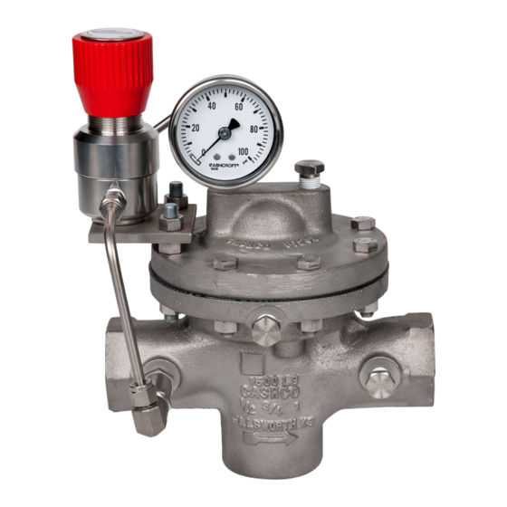
The Model SLR-1 uses the pressure set point of a self-relieving loader to control the outlet pressure of the
main reducing regulator. Sizes are 1/2" (DN15), 3/4" (DN20), 1" (DN25), 1-1/4" (DN32), 1-1/2" (DN40), 2" (DN50),
3" (DN80) and 4" (DN100). This model is suitable for gaseous applications.
II. REFERENCES
Refer to Technical Bulletin SLR-1-TB for tech ni cal
specifications for this reg u la tor.
III. INSTALLATION
For welded installations, all internal trim parts, seals
and diaphragm(s) must be removed from reg u la tor
body prior to welding into pipeline. The heat of fusion
welding will dam age non-metallic parts if not re moved.
1. This regulator may be rotated around pipe axis
360 degrees. For ease of maintenance, the
rec om mend ed position is with the cover dome
(25) up wards.
2. Provide space below, above, and around reg u la-
tor for removal of parts during maintenance.
3. Install block valves and pressure gauges to pro-
vide means for adjustment, operation, bypass,
or removal of the regulator. A pipeline strainer
is recommended before inlet to remove typical
pipe line debris from entering valve and damaging
internal "soft goods", primarily the dynamic seal.
4. Downstream Sensing Installation Considerations
– Internal or External Sensing:
a. The regulator may be installed with inter-
nal or external sensing. Unless otherwise
INSTALLATION, OPERATION & MAINTENANCE MANUAL (IOM)
MODEL SLR-1
DIRECT-ACTING, PRESSURE LOADED,
PRESSURE REDUCING REGULATOR
with SELF-RELIEVING LOADER
CAUTION
SECTION I
SECTION II
CW
CCW –
SECTION III
Installation of adequate overpressure pro tec tion is recom-
mended to pro tect the reg u la tor from overpressure and
all down stream equip ment from damage in the event of
regulator failure.
spec i fied, the regulator is supplied by factory
with internal sensing. The regulator may be
con vert ed in the field to external sensing. (See
Section VII Maintenance, Part G – Converting
Internal/External Sensing.
b. Reference SLR-1-TB, Table -11 for rec om-
men da tions when to apply external sensing.
c. For internal sensing, no external line is re-
quired. For external sensing, use an external
control line. The line is connected from the
1/4" (DN8) NPT tap (Port 5 – See Fig. 5) on
the side of the body di a phragm flange to a
pressure tap down stream of the regulator. Use
1/4" or 3/8" (DN8 or 10) outer di am e ter tubing
or 3/8" (DN10) pipe having an inner di am e ter
equiv a lent to Schedule 40 pipe.
ABBREVIATIONS
–
Clockwise
Counter Clockwise
ITA
–
Inner Trim Assembly
CAUTION
IOM-SLR-1
02-20
Advertisement
Table of Contents

Related Manuals for cashco SLR-1


Summary of Contents for cashco SLR-1
- Page 1 I. DESCRIPTION AND SCOPE The Model SLR-1 uses the pressure set point of a self-relieving loader to control the outlet pressure of the main reducing regulator. Sizes are 1/2" (DN15), 3/4" (DN20), 1" (DN25), 1-1/4" (DN32), 1-1/2" (DN40), 2" (DN50), 3"...
-
Page 2: Principle Of Operation
In ad di tion, note Loader & PI on the nameplate that the Inlet and Outlet pres sure and temperature ratings are at different levels. Model SLR-1 - External Sense Recommended Piping Schematic For Pressure Reducing Station Loader Relieves to atmosphere SECTION IV IV. -
Page 3: Maintenance
Step 9 for a Model regulator to the desired outlet pressure by adjust- SLR-1. The max i mum rise in outlet pres sure on ing the knob on the loading regulator. de creas ing flow should not exceed the 10%. If it does, consult factory. - Page 4 6. Place matchmarks on body (23) and cover dome (25) flanges. Remove cover dome (25). 10. Re move lower diaphragm plate (10). IOM-SLR-1...
- Page 5 If the dy nam ic side seal (27) shows signs 1. 16 rms finish on bore. of sig nif i cant leakage, de ter mine if op er at ing 2. Max 0.015 inch (0.38 mm) clearance IOM-SLR-1...
- Page 6 (27.4). Using thumbs, work the o-ring of the guide bearing (13) until the cap seal (27.4) up and into the groove seal (27.1) “slips into” the cage (19). of the guide bearing (13). NOTE: DO NOT USE TOOLS, LU BRI CANT, IOM-SLR-1...
- Page 7 (20) to rotate against seat ring and a torque wrench on the upper end (21) during tightening. of valve plug (20). Hold torque wrench sta tion ary and rotate diaphragm lock nut 8. This completes ITA preliminary reassembly. (7) to the following torque values: IOM-SLR-1...
- Page 8 TO INTERNALS THAT COULD REN DER THE UNIT IN OP ER A BLE. 2. Inboard Leakage Test. Figure 5: Location of Auxiliary Ports a. Release all loading pressure in cover dome. b. Pressurize inlet to 30 psig (2.1 Barg) with air or GN IOM-SLR-1...
-
Page 9: Diaphragm Replacement
Brass and SST Loaders. For Aluminum new diaphragm sub-assembly if replacement Loaders - contact Cashco Inc. is needed. 4. Remove cap screws that secure loader to 5. Remove di a phragm gas ket (10). - Page 10 6. Inspect all parts for damage and replace if necessary. NOTE: Use only parts man u fac tured and supplied by Cashco, Inc. for these products. See Section X. 7. Place the body (1) into a soft-jawed vise, grasp the flats on the body.
-
Page 11: Section Viii
SECTION VIII VIII. PRESSURE LOADING 2. The Model SLR-1 exhibits a deviation in outlet 1. The Loading pressure for the SLR-1 is supplied controlled pressure when the inlet pressure var- from the inlet (P1) and is regulated by the Pres- ies;... -
Page 12: Troubleshooting Guide
Remedies Differential pressure across diaphragm may A1. Be aware of limits as well as where the various pressures are acting. have exceeded limits. (See Table 6 in SLR-1- Install pressure safety equipment as necessary. Leakage at diaphragm flange. Possible Causes Remedies Body bolts not torqued properly. -
Page 13: New Replacement Unit
(last digit is alpha character that reflects revision level for the product). PARTS "KIT" for FIELD REPAIR: – – Contact your local Cashco, Inc., Sales Rep re sen- NEW REPLACEMENT UNIT: ta tive with the Serial Number and Product code. Identify the parts and the quantity required to repair Contact your local Cashco, Inc., Sales Rep re sen-... - Page 14 Cashco, Inc. does not assume responsibility for the selection, use or maintenance of any product. Responsibility for proper selection, use and maintenance of any Cashco, Inc. product remains solely with the purchaser.
- Page 15 Brass & SST Loader If Aluminum Loader Item No. Repair Parts for Brass & SST Loaders Contact Cashco for Body Replacement Adjusting Screw Knob Nut Knob Spring Button Spring Chamber Diaphragm Subassembly Mounting Bracket for 7.1 ** Diaphragm Brass & SST Loader...
- Page 16 ATEX 2014/34/EU: Explosive Atmospheres and Cashco Inc. Products Cashco, Inc. declares that the products listed in the table below has been found to comply with the Essential Health and Safety Requirements relating to the design and construction of products intended for use in potentially explosive atmospheres given in Annex II of the ATEX Directive 2014/34/EU.
- Page 17 MPRV-H, MPRV-L PBE, PBE-L, PBE-H CA-1, CA-2 CA1, SA1, CA4, SA4, CA5, SA5 DA2, DA4, DA5, DA6, DA8 DA0, DA1, DAP, SAP SLR-1, SLR-2, PTR-1 ALR-1, ULR-1, PGR-1 BQ, BQ(OPT-45), BQ(CRYO) 123, 123(CRYO), 123(OPT-45), 123(OPT-46G) 123-1+6, 123-1+6(OPT-45), 123-1+6(OPT-46G), 123-1+6+S, 123-1+6+S(OPT-40) REGULATORS...
Need help?
Do you have a question about the SLR-1 and is the answer not in the manual?
Questions and answers