Table of Contents
Advertisement
Advertisement
Table of Contents

Subscribe to Our Youtube Channel
Related Manuals for Life Fitness FS4


Summary of Contents for Life Fitness FS4
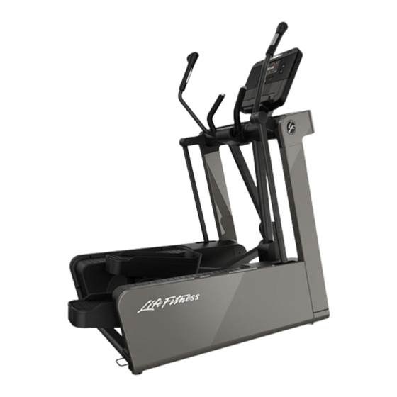
- Page 1 FS4 and FS6 Cross-Trainers Service Manual...
- Page 3 Latin America and Caribbean* Spain Hong Kong Life Fitness, Inc. Life Fitness IBERIA Life Fitness Asia Pacific LTD Columbia Centre III C/Frederic Mompou 5,1º1ª 32/F, Global Trade Square 9525 West Bryn Mawr Avenue 08960 Sant Just Desvern Barcelona 21 Wong Chuk Hang Road Rosemont, IL 60018 U.S.A.
-
Page 4: Table Of Contents
..............37 © Copyright 2018, Life Fitness, LLC. All Rights Reserved. Life Fitness, Hammer Strength, Cybex, ICG and SCIFIT are registered trademarks of Life Fitness, LLC and its affiliated companies and subsidiaries. Brunswick and related trademarks used under license from Brunswick Corporation. -
Page 5: Using This Manual
1. Introduction Using this Manual This service manual provides safe and efficient test and service procedures. Descriptions using the words "left" and "right" refer to the orientation of a user using the product, facing the console. "Front" is the area of the product with the console. The "Rear" of the product is behind the user. Page 3 of 39... -
Page 6: Maintenance
2. Maintenance Maintenance Schedule Item Weekly Monthly Biannually Console Overlay Clean Inspect Bottle Holder Clean Inspect Console Mounting Bolts Inspect Frame Clean Inspect Plastic Covers Clean Inspect Side Panels Clean Inspect Lifepulse Sensors Clean / Inspect Pedals and Straps Clean Inspect Page 4 of 39... -
Page 7: Theory Of Operation
2. Magnets inside this drum move closer and further away from the drum. This creates the variation in user resistance. Detailed Operation The FS4 and FS6 are two models of Rear Entry Cross-Trainers. The FS6 uses electric motors to adjust the stride length. A Hercules console is the user interface. The Console uses two PCBs. - Page 8 The FS6 console has two switches, the left switch adjusts the Stride Length and the right switch adjusts the User Resistance. The FS4 console has one switch on the right that adjusts the User Resistance. The adjustments must be calibrated with the console. The “How To's” section of the Service Manual contains the step by step process for making these calibrations.
-
Page 9: How To's
4. How To's Knowledge Base Knowledge Base for more detailed information. Cup Holder Tools Required: none Time: 15 minutes Remove Cup Holder 1. Place one hand above the cup holder. 2. With the other hand, gently tap the bottom of the cup holder. 3. -
Page 10: Console
Console Tools Required: Phillips screwdriver Time: 15 minutes Disconnect power source Unplug the power cord from the power outlet. WARNING: Shock and electrocution hazard. • Unplug unit and let sit 10 minutes before cleaning or performing maintenance. • Electrical charge can remain in unit after unplugging. •... - Page 11 Complete Installation Operate the unit at all levels to verify proper operation. Page 9 of 39...
-
Page 12: Console Mounting
Console Mounting Bracket Tools Required: • Phillips screwdriver • 17 mm Socket wrench with extension Time: 15 minutes Disconnect power source Unplug the power cord from the power outlet. WARNING: Shock and electrocution hazard. • Unplug unit and let sit 10 minutes before cleaning or performing maintenance. •... - Page 13 2. Install the grounding screw. Item Description Console Grounding screw Console bracket cover Phillips screw, M5 x 14 mm 3. Install console using the four Phillips screws that secure the console bracket to the console. Be careful not to pinch the wires when installing the console.
-
Page 14: Cup Holder
Cup Holder Bracket Tools Required: • Phillips screwdriver • 5 mm Allen wrench Time: 15 minutes Disconnect power source Unplug the power cord from the power outlet. WARNING: Shock and electrocution hazard. • Unplug unit and let sit 10 minutes before cleaning or performing maintenance. •... -
Page 15: Ergo Bar Assembly
Ergo Bar Assembly Tools Required: • Phillips screwdriver • 5 mm Allen wrench Time: 30 minutes Disconnect power source Unplug the power cord from the power outlet. WARNING: Shock and electrocution hazard. • Unplug unit and let sit 10 minutes before cleaning or performing maintenance. •... -
Page 16: Upright Covers
Upright Covers Tools Required: Phillips screwdriver Time: 15 minutes Remove Upright Covers 1. Remove four Phillips screws that secure either the left or right upright cover to the frame. 2. Remove the upright cover. Install Upright Covers Install upright cover using four Phillips screws that secure either the left or right to the frame. Page 14 of 39... -
Page 17: Pedal Lever Clevis
Pedal Lever Clevis Covers Tools Required: Phillips screwdriver Time: 15 minutes Remove Pedal Lever Clevis Covers 1. Remove two Pan Head screws that secure the clevis covers to the rocker arms. Item Description Pan Head screw, M3 x 8 mm Front Clevis Cover Rear Clevis Cover 2. -
Page 18: User Handle
User Handle Tools Required: • Phillips screwdriver • Metric Allen wrench set Time: 15 minutes Remove User Handle 1. Remove the deadshaft covers. Item Description Bolt Deadshaft cover Screw User handle 2. Unplug the connectors wrapped around the deadshaft. 3. Remove the four bolts that hold the user handle to the rocker arm. 4. -
Page 19: Resistance Servo
Resistance Servo Motor Tools Required: • Phillips screwdriver • Ratchet • 6 mm Deep socket Time: 60 minutes Disconnect power source Unplug the power cord from the power outlet. WARNING: Shock and electrocution hazard. • Unplug unit and let sit 10 minutes before cleaning or performing maintenance. •... - Page 20 Install Resistance Servo Motor 1. Install the resistance servo motor with the rear screw and nut. Item Description Resistance Servo Motor Screws Nuts Frame 2. Connect the resistance servo motor cable to the lower controller PCB. 3. Power up unit. This procedure sets the initial starting point for the resistance range of the motor. 4.
-
Page 21: Lower Control
Lower Control Board Tools Required: • Phillips screwdriver Time: 30 minutes Disconnect power source Unplug the power cord from the power outlet. WARNING: Shock and electrocution hazard. • Unplug unit and let sit 10 minutes before cleaning or performing maintenance. •... - Page 22 Install Lower Control Board 1. Install the four screws securing the lower control board to the frame. Item Description Frame Lower control board Screws 2. Connect all cables to the motor control board. 3. Install the screws that secure the left shrouds. Item Description Left outer shroud...
-
Page 23: Mechanism
Eddy Current Brake Mechanism Tools Required: • Phillips screwdriver • 17 mm Socket wrench Time: 30 minutes Disconnect power source Unplug the power cord from the power outlet. WARNING: Shock and electrocution hazard. • Unplug unit and let sit 10 minutes before cleaning or performing maintenance. •... -
Page 24: Eddy Current Brake
5. Remove idler bracket bolts. Item Description Idler bracket bolts Idler bracket 6. Remove the idler bracket and J-hook. Item Description J-hook Idler bracket 7. Remove the nut and washer from the left side of the eddy current brake mechanism threaded shaft. Item Description Nut and washer, for brake... - Page 25 Install Eddy Current Brake Mechanism 1. Loosely install the new eddy current brake to the side brackets. Do not install the nut and washer on the left side of the eddy current brake assembly until the drive belt has been re-installed. Item Description Nut and washer, for brake...
- Page 26 6. Return the hex nut on the J-hook to the distance measured in removal procedure. This will set the tension on the drive belt to approximately 140 - 150 lbs. (63.5 - 68.0 kg). Item Description Adjust distance here Hex nut J-hook 7.
-
Page 27: Servo Calibration
Servo Calibration 1. Go to SELECT WORKOUT screen. 2. Enter MAIN MENU by pressing the following sequence: Right Arrow Up, Right Arrow Down, Right Arrow Up, Right Arrow Down, Pause key. 3. Select Manufacturer Configuration. 4. The next screen displayed is the password screen. Enter password 919. Page 25 of 39... - Page 28 5. The next menu displayed is MANUFACTURER'S CONFIGURATION. Select System Diagnostics from the menu. 6. The SYSTEM TESTS is the next menu to display. Select Servo Calibration from the menu. 7. The last menu to display is SERVO CALIBRATION. When ready press the Calibrate Button. You should hear the servo motor running while it is calibrating.
-
Page 29: Calibrate Eddy Current Brake And Servo
Calibrate Eddy Current Brake and Servo Motor Tools Required: • Phillips screwdriver • 17 mm Socket wrench • 8 mm Open end wrench Time: 30 minutes Disconnect power source Unplug the power cord from the power outlet. WARNING: Shock and electrocution hazard. •... - Page 30 4. Test the servo motor, console function, and cables to console before reinstalling the brake cable. All wire connectors must be plugged in. a. Plug the power back into the machine. b. The servo motor should move to the Level 1 resistance position after the console initializes. If an error on the console is displayed check continuity end to end on all cables from the console to the servo motor.
- Page 31 6. Insert the other end of the brake cable into the pulley on the servo motor. Wrap the cable around counterclockwise and then clip the cable into the slot on the servo motor housing. 7. Clip the end fitting of the brake cable housing into the slot at the bottom of the slide block channel. 8.
- Page 32 11. Install the screws that secure the left shrouds. Item Description Left outer shroud Left inner shroud Screws Complete Installation Operate the unit at all levels to verify proper operation. Page 30 of 39...
-
Page 33: Troubleshooting
Using a voltmeter, verify power at outlet. If no power exists, reset circuit breaker at panel. Line cord is damaged. Replace line cord. Contact Life Fitness Customer Support Services. Line cord is improperly seated Inspect power connection at wall outlet and at in socket. -
Page 34: Mechanical
Mechanical Fault Probable Cause Solution FS4 / FS6 unit moves around Unit is placed on a hard surface. • Place unit on an equipment mat or carpeted during workout. floor. • Adjust the front levelers. Page 32 of 39... -
Page 35: Ecb Led's
ECB LED's LED Number LED Color LED Function Active State Troubleshooting Power In On Solid If LED 1 isn't ON then the ECB isn't getting power. Follow these steps: 1. Check all the cables between the wall outlet and the equipment base. 2. -
Page 36: Reed Switch
Reed Switch 1. Disconnect the Reed Switch Cable from mating ECB P6 connector. 2. Use an ohm meter set on the lowest ohm range. Measure across pin 1 and pin 2 on ECB connector P6. 3. Spin the drum slowly. The ohm meter should change from high ohms to low ohms then back to high ohms. 4. -
Page 37: Schematics
6. Schematics FS4 Schematic Page 35 of 39... -
Page 38: Fs6 Schematic
FS6 Schematic Page 36 of 39... -
Page 39: Glossary
Levelers Adjustable supports located under the unit, used to stabilize the unit. Lifepulse ™ Life Fitness' proprietary hardware and software system designed to measure user's heart rate by making electrical contact at user’s palms. Printed Circuit Board Polar Receiver A device directly in front of the operator that monitors heart rate. Designed by the Polar ®... -
Page 40: Warranty
Who Pays Transportation and Insurance For Service If the Product or any covered part must be returned to a service facility for repairs, We, Life Fitness, will pay all transportation and insurance charges for the first year. You are responsible for transportation and insurance charge after the first year. -
Page 41: Effects Of State Laws
This warranty gives you specific legal rights, and you may have other rights which vary from state to state and country by country. Warranty Information Lifetime 5 years 1 Year FS4 and FS6 Bases Frame Electrical and Mechanical Labor Parts Page 39 of 39...
Need help?
Do you have a question about the FS4 and is the answer not in the manual?
Questions and answers