Life Fitness Axiom Series Assembly Instructions Manual
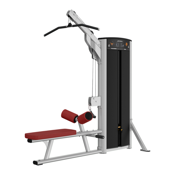
Pulldown/row
Hide thumbs
Also See for Axiom Series:
- Owner's manual (48 pages) ,
- Assembly instructions manual (44 pages) ,
- Owner's manual (44 pages)
Table of Contents
Advertisement
Quick Links
Advertisement
Table of Contents


Need help?
Do you have a question about the Axiom Series and is the answer not in the manual?
Questions and answers