Sign In
Upload
Manuals
Brands
Vacon Manuals
Media Converter
NXP
Vacon NXP Manuals
Manuals and User Guides for Vacon NXP. We have
8
Vacon NXP manuals available for free PDF download: User Manual, Hardware Manual, Manual
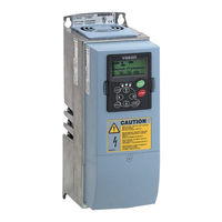
Vacon NXP User Manual (165 pages)
wall-mounted drives standalone drives
Brand:
Vacon
| Category:
Controller
| Size: 2 MB
Table of Contents
11 Appendix
1
About this Manual
3
Start-Up Quick Guide
4
Table of Contents
5
1 Approvals
8
2 Safety
12
The Safety Symbols Used in the Manual
12
Warning
12
Caution
13
Grounding and Earth Fault Protection
14
Electro-Magnetic Compatibility (EMC)
15
Using an RCD or an RCM Device
15
3 Receiving the Delivery
17
Package Label
17
Type Designation Code
18
Storage
21
Removing the Packaging and Lifting the AC Drive
21
Weight of the AC Drive
21
Accessories
22
FR4-FR6 Cable Accessories
22
FR7-FR8 Cable Accessories
24
Product Modified" Label
27
Disposal
27
4 Mounting
28
General Information about Mounting
28
Dimensions for Wall Mounting
29
Wall Mounting of FR4-FR6
29
Wall Mounting of FR7
30
Wall Mounting of FR8
31
Wall Mounting of FR9
32
Dimensions for Flange Mounting
33
Flange Mounting of FR4 to FR6
33
Flange Mounting of FR7 and FR8
35
Flange Mounting of FR9
38
Dimensions for Standalone
39
Standalone (FR10 and FR11)
39
Cooling
40
Cooling of FR4 to FR9
40
Cooling of Standalone AC Drives (FR10 to FR11)
43
5 Power Cabling
44
Cable Connections
44
UL Standards on Cabling
46
Cable Dimensioning and Selection
46
Cable and Fuse Sizes for 208-240 V and 380-500 V, FR4 to FR9
47
Cable and Fuse Sizes for 500-690 V, FR6 to FR9
51
Cable and Fuse Sizes for 380-500 V, FR10 to FR11
53
Cable and Fuse Sizes for 500-690 V, FR10 to FR11
55
Understanding the Power Unit Topology
56
Brake Resistor Cables
57
Preparing for the Cable Installation
58
Cable Installation
58
Frames FR4 to FR7
58
Frames FR8 to FR9
64
Frames FR10-FR11
69
6 Control Unit
70
Control Unit Components
70
Control Unit Cabling
71
Selection of the Control Cables
71
Control Terminals
71
Installation of Option Boards
75
Galvanic Isolation Barriers
76
7 Control Panel
77
Control Keypad
77
Display
78
Navigation on the Control Panel
79
Using the Monitoring Menu (M1)
81
Using the Parameter Menu (M2)
82
Finding the Parameter
82
Editing the Text Values
83
Editing the Numerical Values
84
Using the Keypad Control Menu (M3)
85
Control Place
85
The Keypad Reference Submenu (P3.2)
86
Changing the Rotation Direction
87
Disabling the Stop Motor Function
87
Special Functions in the Keypad Control Menu
87
Using the Active Faults Menu (M4)
88
The Fault Time Data Record
88
Using the Fault History Menu (M5)
90
Resetting the Fault History Menu
91
Using the System Menu (M6)
91
Changing the Language
95
Changing the Application
95
Copy Parameters (S6.3)
96
Comparing the Parameters
99
Security
101
Keypad Settings
105
Hardware Settings
107
System Info
112
Using the Expander Board Menu (M7)
117
Examining the Connected Expander Boards
118
Finding the Expander Board Parameters
119
Further Keypad Functions
120
8 Commissioning and Additional Instructions
121
Commissioning Safety
121
Commissioning of the Drive
122
Operation of the Motor
122
Checks before Starting the Motor
122
The Run Test Without the Motor
123
Start-Up Test
123
Identification Run
123
Connecting the Motor to the Process
123
Measuring the Cable and Motor Insulation
124
Installation in an IT System
124
Frames FR4, FR5, and FR6
124
Frame FR7
125
Frames FR8 - FR11
127
Maintenance
127
Capacitor Reforming
128
9 Technical Data for NXS and NXP
129
AC Drive Power Ratings
129
Mains Voltage 208-240 V
129
Mains Voltage 380-500 V
131
Mains Voltage 500-690 V
133
Overload Capability
135
Brake Resistor Ratings
136
Vacon ® NXS and NXP - Technical Data
140
The Compliance with the Product Standard IEC/EN 61800-3 + A1
145
Environment Definitions in Product Standard IEC/EN 61800-3 + A1
147
10 Fault Tracing
148
Resetting a Fault
148
Fault Codes
150
Power Losses for 380-500 V
157
Appendix 1
157
Power Losses of 500-690 V
162
Advertisement
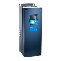
Vacon NXP Manual (55 pages)
Frequency converters
Brand:
Vacon
| Category:
Media Converter
| Size: 0 MB
Table of Contents
Table of Contents
2
Index
2
1 General
3
Heat Exchanger Application
3
2 Control I/O
4
3 Parameter Lists
5
Monitoring Values (Control Keypad: Menu M1)
5
FB Monitor
6
Status Word, ID43
6
Status Word 2, ID1800
6
Fault Word 1, ID1172
7
Fault Word 2, ID1173
7
Warning Word 1, ID1174
7
Fault Word 10, ID1202
8
Warning Word 10, ID1269
8
Basic Parameters (Control Keypad: Menu M2 G2.1)
9
Input Signals (Control Keypad: Menu M2 G2.2)
10
Output Signals (Control Keypad: Menu M2 G2.3)
11
Analogue Output 1
11
Analogue Output 2
11
Analogue Output 3
12
Relay Output 1
12
Relay Output 2
13
Relay Output 3
13
Relay Output 4
13
Relay Output 5
14
Relay Output 6
14
Drive Control Parameters (Control Keypad: Menu M2 G2.4)
15
Prohibit Frequency Parameters (Control Keypad: Menu M2 G2.5)
15
Motor Control Parameters (Control Keypad: Menu M2 G2.6)
16
Protections (Control Keypad: Menu M2 G2.7)
17
PID Control Parameters (Control Keypad: Menu M2 G2.9)
18
Flow Control Parameters (Control Keypad: Menu M2 G2.10)
19
Fieldbus Parameters (Control Keypad: Menu M2 G2.11)
20
Keypad Control (Control Keypad: Menu M3)
21
System Menu (Control Keypad: M6)
21
Expander Boards (Control Keypad: Menu M7)
21
4 Description of Parameters
22
Current Limit
22
Minimum/Maximum Frequency
22
U/F Ratio Selection
22
Linear and Squared Change of Motor Voltage
23
Programmable U/F Curve
23
U/F Optimisation
23
Nominal Speed and Current of Motor
24
Nominal Voltage and Frequency of Motor
24
Parameter Conceal
24
I/O Frequency Reference Selection
25
Keypad/Fieldbus Frequency Reference Selection
25
PID Controller Gain
25
PID Controller I-Time
25
PID Controller Function as I-Controller
26
PID Activation
27
PID Output Curve with the Values of Example 2
27
PID Output with the Values of Example 3
27
Analogue Output 1 Function
28
DIN3 as DC-Brake Command Input
28
DIN3 Function
28
Analogue Output 1 Filter Time
29
Analogue Output 1 Inversion
29
Analogue Output 1 Minimum
29
Analogue Output 1 Scale
29
Output Frequency Limit Supervision Function
30
Output Frequency Limit Supervision Value
30
Output Signals Via Relay Outputs RO1 and RO2
30
Relay Output 1 Function
30
Actual Value 1 Minimum and Maximum Scale
31
Actual Value Selection
31
Example of Actual Value Signal Scaling
31
PID Controller Reference Signal
31
AI1 Custom Setting Minimum Maximum
32
AI1 Signal Filter Time
32
AI1 Signal Range
32
PID Error Value Inversion
32
AI1 Signal Inversion
33
AI2 Signal Filter Time
33
AI2 Signal Range
33
AI2 Custom Setting Minimum/Maximum
34
AI2 Signal Inversion
34
Acceleration/Deceleration Ramp 1 Shape
35
Brake Chopper
35
Start Function
35
DC-Braking Current
36
DC-Braking Time at Stop
36
Stop Function
36
Prohibit Frequency Area 1; Low and High Limit
37
Acceleration/Deceleration Ramp Speed Scaling Ratio between Prohibit Frequency Limits 23457
38
DC-Braking Frequency at Stop and Start
38
Flux Brake
38
Flux Braking Current
38
Motor Control Mode
39
Switching Frequency
39
U/F Curve, Middle Point Frequency and Voltage
39
Voltage at Field Weakening Point
39
Overvoltage Controller
40
Undervoltage Controller
40
Earth Fault Protection
41
Output Phase Supervision
41
Response to External Fault
41
Response to the 4Ma Reference Fault
41
Motor Thermal Protection: Motor Ambient Temp. Factor
42
Motor Thermal Protection: Motor Duty Cycle
42
Motor Thermal Protection: Time Constant
42
Motor Temperature Calculation
43
Stall Characteristics Settings
43
Stall Current Limit
43
Stall Protection
43
Stall Frequency Limit
44
Stall Time
44
Underload Protection
44
Underload Protection, Field Weakening Area Load
44
Automatic Restart: Trial Time
45
Automatic Restart: Wait Time
45
Underload Protection, Zero Frequency Load
45
Underload Time
45
Automatic Restart
46
Automatic Restart: Start Function
46
Input Phase Supervision
46
Response to Undervoltage Fault
46
Actual Value Supervision Delay
47
Actual Value Supervision Function
47
Actual Value Supervision Limit
47
Response to Fieldbus and Slot Fault
47
Fieldbus Data out Selections 1 to 8
48
Some Typical Values
48
Constant Speed
49
Coolant Inlet Pressure, Minimum and Maximum
49
Delayed Fault
49
Relay Output 3 Function
49
AI3 Signal Selection
51
Coolant Inlet Pressure Alarm Limit
51
Coolant Inlet Pressure Supervision
51
DIN2 Input
51
Autochange Interval
52
Control Place
53
Keypad Control Parameters
53
Keypad Direction
53
Stop Button Activated
53
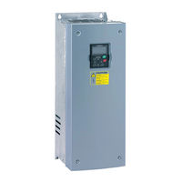
vacon NXP Hardware Manual (78 pages)
system drive
Brand:
vacon
| Category:
Controller
| Size: 16 MB
Table of Contents
Table of Contents
5
1 Introduction
7
Scope of Supply
7
Definitions and Abbreviations
7
Related Brochures and Manuals
7
Project Specifications
8
Parameters
8
Sections and Options
9
2 Available Sections
10
Auxiliary Device Section
10
Main Incoming Section
11
Non-Regenerative Front-End Section
13
Active Front-End Section
15
Inverter Unit Section
17
Drive Sizes FR4-FR8
17
Drive Sizes FI9-FI14
20
Dynamic Brake Section
23
Transport Split Unit
24
3 Installation
25
Safety Notes
25
Warnings
25
Cautions
26
Earthing and Earth Fault Protection
27
Storage
28
Lifting and Moving the Sections
29
Fixing the Sections
30
Free Space Around the Cabinet
30
Fixing the Cabinet to the Floor or Wall
31
Back-To-Back Installation
32
Connecting Sections
33
Fixing Cabinets to each Other
33
Common Busbars
34
Cabling
35
Earthing
35
Mains and Motor Connection
35
Control Connections
40
Screw Tightening Torques
41
4 Service
42
Warranty
42
Maintenance
42
Removing the Drives from the Cabinet
43
Ius_4 / Ius_6
43
Ius_7 / Ius_8
44
Ius_9 / Ius_10
45
Ius_12
48
Ius_13 / Ius_14
51
5 Technical Information
54
Control and Interface
54
Control Without Speed Feedback (Open Loop)
54
Control with Speed Feedback (Closed Loop)
54
Load Definitions
54
Pump and Fan Load
55
Ol( ) > Ol
56
OL( Base ) > OL( N Max ) for Constant Torque Load
56
OL( N Base ) > OL
56
Starting Torque >> OL( N Max ) for Constant Torque Load
57
OL( N Base ) < OL
58
N Max ) for Constant Power Load
58
Max ) for Constant Power Load
59
Technical Specifications for VACON ® Drives
60
NXN - Non-Regenerative Front End Units
60
Technical Specifications for VACON 5.3.1 NXN - Non-Regenerative Front End Units
60
NXA - Active Front-End Units
62
NXI - Inverter Units
64
NXB - Brake Chopper Units
69
6 Supplied Documentation
70
Documentation Examples
71
Cable Connection Table
71
Parts List
72
Wiring List
73
Circuit Diagram
74
Switchgear Layout Drawing
75
Device Layout Drawing
76
Advertisement
Vacon NXP User Manual (94 pages)
frequency converters, shaft synchronization
Brand:
Vacon
| Category:
Media Converter
| Size: 1 MB
Table of Contents
Table of Contents
3
1 Introduction
5
Requirements
6
Trial Time Period
6
2 Control I/O
7
3 Connection of Signals between Master and Follower Drive (OPT-A7)
8
4 Jumper Setting on the OPT-A7 Board
9
5 Terminal to Function" (TTF) Programming Principle
10
Defining an Input/Output for a Certain Function on Keypad
10
Defining a Terminal for a Certain Function with Ncdrive Programming Tool
11
Defining Unused Inputs/Outputs
12
6 Shaft Synchronization Application - Parameter Lists
13
Monitoring Values (Control Keypad: Menu M1)
13
Basic Parameters (Control Keypad: Menu M2 G2.1)
14
Input Signals
15
Basic Settings (Control Keypad: Menu M2 6.3.2 G2.2.2)
15
G2.2.1)
15
Analogue Input
15
Analogue Input 2 (Control Keypad: Menu M2 G2.2.3)
16
Free Analogue Input, Signal Selection (Keypad: Menu M2 G2.2.4)
16
Digital Inputs (Control Keypad: Menu M2 G2.2.5)
17
Output Signals
18
Delayed Digital Output 1 (Keypad: Menu M2 G2.3.1)
18
Delayed Digital Output 2 (Keypad: Menu M2 G2.3.2)
18
Digital Output Signals (Control Keypad: Menu M2 G2.3.3)
19
Limit Settings (Control Keypad: Menu M2 G2.3.4)
20
Analogue Output 1 (Control Keypad: Menu M2 G2.3.5)
21
Analogue Output 2 (Control Keypad: Menu M2 G2.3.6)
21
Analogue Output 3 (Control Keypad: Menu M2 G2.3.7)
22
Mechanical Brake (Control Keypad: Menu M2 G2.3.8)
22
Drive Control Parameters (Control Keypad: Menu M2 G2.4)
23
Motor Control Parameters (Control Keypad: Menu M2 G2.5)
24
PMSM Settings (Control Keypad: Menu M2 G2.5.19)
25
Protections (Control Keypad: Menu M2 G2.6)
26
Fieldbus Parameters (Control Keypad: Menu M2 G2.7)
28
Torque Control Parameters (Control Keypad: Menu M2 G2.8)
29
Shaft Synchronization Parameters (Control Keypad: Menu M2 G2.9)
30
License Key (Control Keypad: Menu M2 G2.10)
31
Keypad Control (Control Keypad: Menu M3)
31
System Menu (Control Keypad: Menu M6)
31
Expander Boards (Control Keypad: Menu M7)
31
7 Description of Parameters
32
Vacon Shaft Synchronization Application
32
Keypad Control Parameters
85
Application Specific Variables in the Monitor Menu and Fieldbus Interface
86
8 Shaft Synchronization Operation
87
Shaft Synchronization Fieldbus Interface
90
9 Appendices
91
Closed Loop Parameters (ID's 612 to 621)
91
Note on Use of Permanent Magnet Motors ("AC Brushless" Motors)
91
Parameters of Motor Thermal Protection (ID's 704 to 708)
92
Parameters of Stall Protection (ID's 709 to 712)
92
Fieldbus Control Parameters (ID's 850 to 859)
92
10 Shaft Synchronization Application Specific Fault Codes
93
11 Commissioning of Shaft Synchronization Application
93
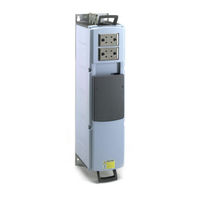
Vacon NXP Hardware Manual (60 pages)
liquid cooled enclosed solutions
Brand:
Vacon
| Category:
Controller
| Size: 11 MB
Table of Contents
Table of Contents
4
Vacon
5
1 Introduction
6
Scope of Supply
6
Related Brochures and Manuals
6
Available Drive Sizes
7
2 Enclosed Solution Sections
8
Incoming Section
9
Drive Section
10
DU/DT and Internal Cooler Section
11
Heat Exchanger Section
12
3 Installation
13
Safety Notes
13
Danger
13
Warnings
14
Earthing and Earth Fault Protection
15
Storage
16
Lifting and Moving the Cabinets
17
Fixing the Cabinets
18
Free Space Around the Cabinet
18
Fixing the Cabinet to the Floor or Wall
19
Cabling
20
Earthing
20
Mains and Motor Connection
20
Cooling Pipe Connections
22
Control Connections
23
Screw Tightening Torques
24
4 Service
25
Warranty
25
Proactive Maintenance as Recommended by Manufacturer
25
Replacement Instructions
29
Drives
29
Fuses
35
Cabinet Fans for Du/Dt and Internal Cooler
36
Internal Cooler
38
5 Technical Information
40
Control and Interface
40
Control Without Speed Feedback (Open Loop)
40
Control with Speed Feedback (Closed Loop)
40
Load Definitions
40
Pump and Fan Load
41
OL( Base ) > OL
42
N Max ) for Constant Torque Load
42
Starting Torque >> OL( Max ) for Constant Torque Load
43
N Max ) for Constant Power Load
44
Max ) for Constant Power Load
45
Technical Specifications for VACON ® NXP Liquid Cooled Drives
46
6 Supplied Documentation
50
Documentation Examples
51
Cable Connection Table
51
Parts List
52
Wiring List
53
Circuit Diagram
54
Switchgear Layout Drawing
55
Device Layout Drawing
56
Appenix
57
P&ID Drawings
58
Vacon NXP User Manual (32 pages)
Brand:
Vacon
| Category:
Media Converter
| Size: 0 MB
Table of Contents
Table of Contents
2
General
3
Lonworks OPTION BOARD TECHNICAL DATA
4
General
4
Physical Media and Wiring
5
Profiles
6
Lonworks FIELDBUS BOARD LAYOUT and CONNECTIONS
7
Lonworks OPT-C4 Option Board
7
Grounding of Bus Cable Shield in OPT-C4
8
Bus Termination Resistors
10
LED Indications
10
INSTALLATION of VACON NX Lonworks BOARD
12
Board Information Sticker
14
Commissioning
15
Fieldbus Board Parameters
15
Start-Up Test
16
Lonworks INTERFACE
17
General
17
Input Network Variables
19
Output Network Variables
22
Network Configuration Variables
25
Process Data
27
Fault Tracking
28
Vacon NXP User Manual (24 pages)
AC DRIVES, add-on instruction for ethernet/ip
Brand:
Vacon
| Category:
DC Drives
| Size: 0 MB
Table of Contents
Table of Contents
3
1 Introduction
4
Purpose of this Document
4
Compatibility
5
2 Available Add-On Instructions and Features
5
Vacon_Drive_20_70
5
Vacon_Drive_21_71
6
Vacon_Nxp_111_117
7
Vacon_100_111_117
9
3 Configuration of the AC Drive
12
Ethernet/Ip Parameterization
12
AC Drive Parameterization
13
4 Using the Add-On Instruction (AOI)
13
Importing the AOI
14
Configuring the PLC I/O
16
Creating a Task/Program/Routine in Rslogix5000
19
Setting up the AOI
21
Vacon NXP User Manual (16 pages)
Brand:
Vacon
| Category:
Controller
| Size: 0 MB
Table of Contents
Table of Contents
2
1 ENDAT/SSI, Sin-Cos Option Board OPT-BE
3
OPT-BE Layout and Description
3
OPT-BE Jumpers
4
OPT-BE Leds
5
I/O Terminals on OPT-BE, Encoder Terminal X6
5
OPT-BE Parameters
6
OPT-BE Monitored Values
6
2 Sin-Cos Option Board OPT-AK
7
OPT-AK Layout and Description
7
OPT-AK Jumper Settings
8
I/O Terminals on OPT-AK, Encoder Terminal X6
8
OPT-AK Parameters
9
OPT-AK Monitored Values
9
3 Sin-Cos with Pulse Output Option Board OPT-AR
10
OPT-AR Layout and Description
10
OPT-AR Jumper Settings
11
I/O Terminals on OPT-AR, Encoder Terminal X6
11
I/O Terminals on OPT-AR, Pulse Output X3
12
OPT-AR Parameters
12
OPT-AR Monitored Values
12
4 Installation
13
Installing Option Boards
13
Advertisement
Related Products
Vacon NXP/C 5 Series
Vacon NXP/C 6 Series
Vacon NXL series
Vacon NX_0590 5
Vacon NX_0730 5
Vacon NX_0650 5
Vacon NX_0300 5
Vacon NX_0920 5
Vacon NX_0170 6
Vacon NX_0385 6
Vacon Categories
Controller
Media Converter
DC Drives
Inverter
Power Supply
More Vacon Manuals
Login
Sign In
OR
Sign in with Facebook
Sign in with Google
Upload manual
Upload from disk
Upload from URL