
Subscribe to Our Youtube Channel
Related Manuals for Bentone ST 120


Summary of Contents for Bentone ST 120
- Page 1 CR00118 178 172 15-1 2020-12-10 Providing sustainable energy solutions worldwide Installation- and maintenance instruction ST 120 R RV LMO14 AS 47 Translation of the original instructions.
- Page 2 Beispiel Manualer på övriga språk www.bentone.com\nedladdning 352011030141 Serial no. 1234567 Man.Year 2019 Designation BF 1 KS 76-24 eller scanna QR-koden BF 1 Type Model BF 1 KS 76-24 Cap. Min-Max LIGHT OIL 35-90kW 1,25-6,0 cSt 7-14bar Skriv in brännarens artikelnummer som finns på din...
-
Page 3: Table Of Contents
1. General Information __________________________________ 4 6. Instructions Pump __________________________________ 24 6.1 SUNTEC AS ____________________________________ 24 2. Technical data _______________________________________ 7 2.1 Dimensions ST 120 _______________________________ 7 7. Oil burner control ___________________________________ 30 2.2 Dimensions, flanges _______________________________ 8 7.1 Wiring diagram _________________________________ 30 2.3 Burner installation _________________________________ 8... -
Page 4: General Information
• Burner pipes, fan wheels and air dampers may contain sharp edges. • The surface temperature of the burner’s components can exceed 60 °C. • Caution: The burner has moving parts, and there is risk of crushing injuries. 165 105 01 Bentone... - Page 5 - flue gas ducts and combustion air ducts are not blocked - all actuators and control and safety devices are in working order and correctly set • After commissioning, if a steady red light on the burner control is displayed, contact your installation technician. Bentone...
- Page 6 Delivery check • Make sure everything is delivered and the goods have not been damaged during transit. • If something is wrong with a delivery, report it to the supplier. • Transport damage must be reported to the shipping company. Bentone...
-
Page 7: Technical Data
• Light oil, B10 heating oil/biofuel blend (as defined in DIN V51603-6) and is used for: • Water heating generators • Hot air generators (these require LMO 24 255 C2E) 2.1 Dimensions ST 120 * Min. recommended distance to floor. Ø B ST120... -
Page 8: Dimensions, Flanges
Length of blast tube Flange Flange 1 Flange 2 ø89,7 ø90 130-150 125-150 2.3 Burner installation 2.3.1 Hole patten Make sure the hole pattern on the boiler is designed for burner flange. Combustion device ST 120 R,RV ø 90 ø 125-150 Bentone... -
Page 9: Working Field St 120R/Rv
2.5.1 Electric Specification Burner correspond to IP 20 Type Motor Complete Sound burner ST 120 R, RV 90W 0,75A 230V 230V 0,8A 70 dBA ± 0,5 50/60Hz 4µF 50Hz 2.4 Setting of brake plate and air flow *NB It is important that... -
Page 10: Recommended Nozzles And Pressures
/s (cSt) at a density of 830 kg/m 2.7.1 Burner with preheater Allow for a reduction in oil quantity of 5–20% with preheating owing to: • Temperature increases at the nozzle. • Nozzle design. • Capacity (the higher the capacity the lower the difference). Bentone... -
Page 11: Description
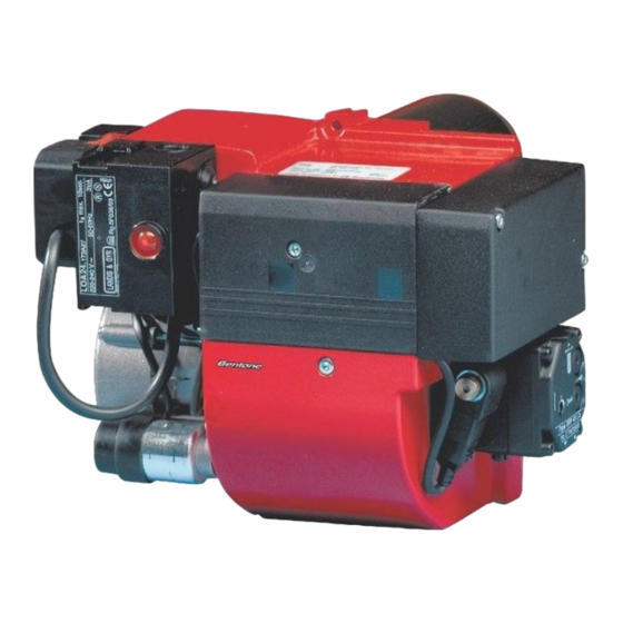
17. Adjustment, air damper Control box 10. Connecting pipe 18. Photoresistor Ignition transformer 11. Air damper 19. Motor Ignition cables 12. Solenoid valve 13. Pump Nozzle assembly Nozzle 14. Drive coupling Brake plate 15. Indication, air damper Blast tube 16. Fan wheel Bentone... -
Page 12: General Instructions
Otherwise, there is a risk of soot build up, poor efficiency or condensation in the chimney. The system must be fine- tuned at start-up. The temperature in the chimney at a depth of 0.5 m must be at least 60 °C to prevent condensation. 165 205 19 Bentone... -
Page 13: Delivery Inspection
• Burners must be connected to an all-pole switch. • Connection must conform to the wiring diagram. • Use appropriately sized fuses. If any electrical connection is used other than that recommended by Enertech, there may be a risk of damage to property and personal injury. Bentone... -
Page 14: Burner Installation
3.6.5 Check oil line seals Once the burner has been installed and commissioned, the seals of the various coupling elements should be checked. When a leak is detected, it is usually sufficient to tighten the coupling element that is leaking. 165 205 20 Bentone... -
Page 15: Basic Settings
4. Basic settings 4.1 Example of basic settings 4.1.1 Choice of nozzle ST 120 R 69-16 Burner output 30 kW Estimated nozzle output: 30 / 11.86* 2.53 kg/h Choice of nozzle according to the table (refer to Technical data). According to the nozzle table, this provides the following nozzle. - Page 16 The setting value for 30 kW according to basic settings tables (Setting values). Air setting 10.0 Nozzle assembly setting * Energy value of EO1 fuel oil = 11.86 kWh/kg Nozzle assembly setting ST 120R, RV mbar Air setting ST 120R, RV mbar � Bentone...
- Page 17 4.1.5 Setting the air quantity Turn the air intake clockwise to increase airflow and anticlockwise to decrease airflow. Nozzle assembly control Air control Bentone...
-
Page 18: Burner Servicing
Fit the front cover and insert the burner into the boiler. Connect the Europlug and turn on the mains power. Start the burner and check the combustion. When servicing/replacing components that affect combustion, an analysis and soot test must be carried out on the installation 165 205 22 Bentone... - Page 19 (refer to Technical data). Connect the preheating and ignition cables. Fit the front cover and insert the burner into the boiler. Connect the Europlug and turn on the mains power. Start the burner and check the combustion. Bentone...
-
Page 20: Replacing The Oil Pump
Connect the Europlug and turn on the mains power. Turn on the burner, air the pump, adjust the pressure, and check the combustion. When servicing/replacing components that affect combustion, an analysis and soot test must be carried out on the installation Bentone... -
Page 21: Replacing The Fan Motor And Fan Wheel
Assemble the fan housing and front cover and insert the burner into the boiler. Connect the Europlug and turn on the mains power. Start the burner and check the combustion. When servicing/replacing components that affect combustion, an analysis and soot test must be carried out on the installation Bentone... -
Page 22: Servicing The Air Intake And Intake Cone
Turn on the burner control. Refit the cover. Connect the Europlug and turn on the mains power. Start the burner and check the combustion. When servicing/replacing components that affect combustion, an analysis and soot test must be carried out on the installation Bentone... -
Page 23: Replacing Individual Electrical Package Components
Remove the cable of the component to be replaced. Connect the new cable. Refit the electrical package (do not forget the Europlug). Turn on the burner control. Connect the Europlug and turn on the mains power. Start the burner and check the combustion. Bentone... -
Page 24: Instructions Pump
Components Suction line G 1/4” Return line G 1/4”and internal by- pass plug Nozzle outlet G 1/8” Pressure gauge port G 1/8” Vacuum gauge port G 1/8” Pressure adjustment 165 105 20 2020-11-03 Bentone... - Page 25 Gear-set Vacuum gauge port Oil under suction By-pass Oil under pressure By-pass plug plug removed By-passed oil inserted returned to tank, or to suction Return Inlet Return plugged One pipe installation Two pipe installation 165 105 20 2020-11-03/2 Bentone...
- Page 26 150 150 139 150 108 150 150 150 150 **Q = pump capacity @ 0 bar / Pumpenleistung bei 0 bar capacité de l'engrenage à 0 bar/portata della pompa a 0 bar. Two pipe lift system 165 105 20 2020-11-03/3 Bentone...
- Page 27 The tables state the total suction line length in metres at a nozzle capacity of 9,5 Gph. Max. permissible pressure at the suction and pressure side is 2,0 bar. 165 105 20 2020-11-03/2 Bentone...
- Page 28 Close the oil supply to the burner. Loosen the pump cover’s screws. Remove the filter and gasket. Mount new gasket and filter. Refit the cover. Open the oil supply. Start the burner and check seals and combustion. 165 105 20 2020-11-03/3 Bentone...
- Page 29 Shaft seal kit (lip seal + protective cone) By-pass plug G 1/4 gasket G 1/4 steel plug (1-pipe system) Filter Cover gasket Cover Pressure gauge port or vacuum gauge port screw, O-ring 10. Coil 11. Tube assy 165 105 20 2020-11-03/2 Bentone...
-
Page 30: Oil Burner Control
7. Oil burner control Wiring diagram Alt 2 Alt 3 Alt 4 Alt. 1 Enl DIN 4791 165 205 56 Bentone... - Page 31 Reaction time on flame failure: < 1 s < 1 s Ambient temperature: -5 +60°C -20 - +60°C Min. current with flame established: 45 µA dc 45 µA dc Max. photo current at start: 5,5 µA dc 5,5 µA dc Bentone...
-
Page 32: Colour Codes Lmo14/24
If the reset button is instead kept pressed a second time for at least 3 seconds, you can, via an interface, obtain the corresponding information on a computer or flue gas analyser. To return to normal operation: Press the reset button for 1 second. Bentone... -
Page 33: Fault Location
Check preheater function Preheater temperature too low Adjust the preheater‘s set operating tem- New oil type perature Check that the oil used has the physical parameters that the burner is rated for. If not, change the oil. 165 105 09 Bentone... -
Page 34: Delayed Ignition
Change the oil or the pump's oil parameters Pump worn Replace the pump Pump run using impure oil that has worn the Replace pump and install self-cleaning pump out prematurely filter in the oil system Blocked pump filter Check, clean pump filter Bentone... -
Page 35: Log Of Flue Gas Analysis
9. Log of flue gas analysis Owner Adresss Tel. no: Installation Tel. no: Boiler Type Make Power Bentone Burner Type Model Serial no. Fuel Step 1 Step 2 Step 3 Draught in fireplace Fan Press mbar Filter smoke number Flue gas temp. °C... -
Page 36: Oil Burners Maintenance Instructions
10. Oil burners maintenance instructions General information If the burner starts but does not ignite Keep the boiler room clean. Ensure that the boiler Make an attempt to start the burner. room has permanent fresh air intake. Switch off before Never make close repeated start attempts. - Page 40 Enertech AB. P.O Box 309, SE-341 26 Ljungby. www.bentone.se, www.bentone.com...
Need help?
Do you have a question about the ST 120 and is the answer not in the manual?
Questions and answers