Table of Contents
Advertisement
Advertisement
Table of Contents

Subscribe to Our Youtube Channel
Related Manuals for UNI-T UT620C


Summary of Contents for UNI-T UT620C
- Page 1 110401111444X...
-
Page 2: Table Of Contents
Contents Ⅰ. Safety Information ..................2 Ⅱ. Overview ....................2 Ⅲ. Range and Accuracy ................. 3 Ⅳ. Technical Specifications ................3 Ⅴ. External Structure ..................5 Ⅵ. Operating Instructions ................5 1. Power on/off ................... 5 2. Check battery voltage ..............5 3. -
Page 3: Safety Information
I. Safety Information Thank you for purchasing the product, for better use, please read the user manual carefully and follow the safety information below. Pay special attention to safety when using the product. Do not measure any live object. Make sure that the resistor or metal object to be measured is de-energized before measurement, otherwise, it may damage the product. -
Page 4: Range And Accuracy
Testing Current ±0.1%FS±20dgt 1.2A (18°C~28°C; 1.2A <70%rh) 1.2A 1.2A UT620C 0.5A 0.05A ~100.00 0.5mA 0.05mA Note: ±0.2%FS±20dgt (18°C~28°C; >70%rh / -10°C~50°C; <80%rh) IV. Technical Specifications The meter is mainly applied to measure resistance of conductor, contact resistance of switch, connector and relay, resistance and contact resistance of coil, motor and transformer winding. - Page 5 Communication Micro USB cable (1pc) cable Data storage Store 500 groups of data. “MEM” to indicate storage; “FULL” to indicate full storage. Data viewing Symbol “MR” appears Overrange Symbol “OL” appears indication Battery voltage Battery voltage is displayed in real time. Please charge the battery in time if the meter indicates low battery.
-
Page 6: External Structure
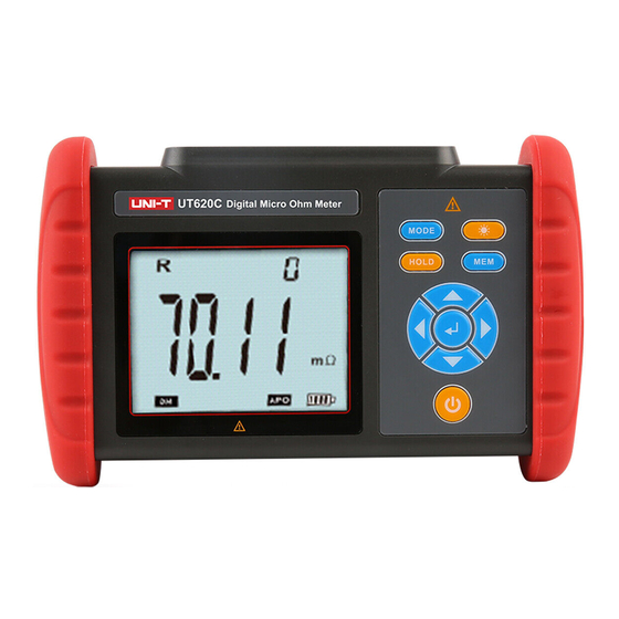
V. External Structure 1. USB transmission/charging port 2. Charging indicator light 3. Connectors for test leads 4. LCD display 5. Rubber insulation protector 6. Functional buttons 7. Test leads (red: 1pc; black: 1pc) VI. Operating Instructions 1. Power on/off Press “ ”... -
Page 7: Resistance Precision Testing
3. Resistance precision testing Please clear the insulation layer and the oxidation layer on the surface of the object to be measured before test. Do not perform live test for resistance or DC low resistance. Live test may damage the meter. Test clips may be oxidized after they are used for a long time. - Page 8 Measure the resistance between electric meter and down conductor Grounding wire of electric meter Copper busbar Black Equipment grounding wire Down conductor Measure the resistance between metal connectors Metal connectors Black...
-
Page 9: Backlight Control
Measure the resistance of contact points of relay Relay Black 4. Backlight control In power-on state, press “ ” to turn on/off backlight. The backlight function applies in dark environments. The default state of backlight is off when powering on the meter. 5. -
Page 10: Data Viewing/Deletion
6. Data viewing/deletion After the meter is powered on or measurement is completed, the meter switches to data viewing mode and “ ” appears on the LCD when “ ” is pressed. Press “◀” or “▶” to set the step as 1 (group), press “ ” or “ ” to set the step as 10 (groups). -
Page 11: Line Resistance Calibration (Clear Residual Resistance)
8. Line resistance calibration (clear residual resistance) Short-circuit both clips first, then long press “ ” for 2 to 3 seconds after the displayed value is stabilized, to complete calibrating line resistance, as shown below: Note: Only when the displayed value is stabilized can “ ” be pressed. Black VII. -
Page 12: Packing List
VIII. Packing List Meter 1 pc Carrying bag 1 pc USB cable (data transmission) 1 pc Test lead 2 pcs (red: 1pc; black: 1pc) Power Charger 1 pcs User manual 1 pcs Note: The content of this user manual cannot be used as a reason for using the product for special purposes.
Need help?
Do you have a question about the UT620C and is the answer not in the manual?
Questions and answers