Table of Contents
Advertisement
Quick Links
Advertisement
Table of Contents

Related Manuals for UNI-T UT255A


Summary of Contents for UNI-T UT255A
- Page 1 P/N:110401103626...
-
Page 2: Table Of Contents
Contents TITLE PAGE Warning I. Introduction II. Electrical Symbols III. Model Comparison IV.T echnical Specifications V. Meter Description VI. Display Mode 1. LCD Display 2. Special Icon Description 3. Display Examples VII. Operating Instructions 1. Measuring Instruction (1) Power On/Off (2) General Measurement... -
Page 3: Title Page
TITLE PAGE Warnings (3) PEAK Measurement Thank you for purchasing UNIT series high voltage clamp ammeter. (4) Data Hold In order to use the product properly, please follow instructions below: (5) Data Save -----Read this manual carefully and the operator is required to fully (6) Data Access understand the manual and operate skillfully before beginning (7) Data Delete... -
Page 5: Introduction
features such as moisture proof, high temperature resistance, anti-strike and I. Introduction bending, high insulation, extendibility ,ect. High voltage clamp ammeter stands out from traditional concept and is With the insulation rod, the meter can measure leakage current in high- especially designed for on-line measurement on current, leakage current of voltage lines below 60kV and on-line current, and identify if zinc oxide high-voltage lines and determining working status of zinc oxide arrester. -
Page 6: Electrical Symbols
Range Model Resolution Jaw Size Notes II. Electrical Symbols General Type UT255A 10uA 600A 10uA 33mm Extreme danger! To avoid personal injury or accidents in case of Special, with electric shock, observe safety rules strictly. wireless UT255B... - Page 7 IV. Technical Specifications Jaw Opening 33mm Sampling Rate 2 times per second To measure high-and low-voltage AC leakage current Measuring Range AC 0.01mA 600.0A 50/60Hz auto Functions and on-line current; indirectly obtain ratio of current Resolution 10uA transformer 0.01mA 600A automatically switch Function Switchover DC6V Alkaline dry battery 1.5V AAA 4 Power...
- Page 8 Tester 335g battery included ; total weight To measure line voltage below 60kV operate with Line Voltage Weight 2.5Kg insulation rod and battery included insulation rod Operating Press HOLD button to hold data under general 40 ; 80%Rh Temperature /Humidity Data Hold measuring mode, indicated by HOLD...
-
Page 9: Meter Description
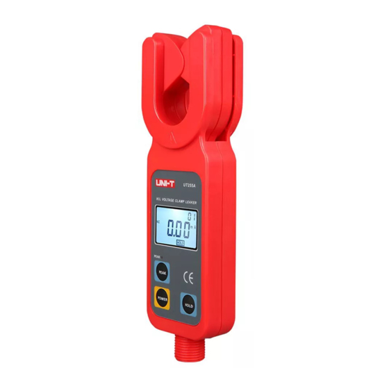
V. Meter Description 1. Clamp Jaw (Guide zone included) 2. UT255A Tester 3. LCD Display 4. PEAK Measuring Indication 5. PEAK Button 6. POWER Button 7. HOLD Button * 8. UT255B Receiver 9. Insulation Rod connection Terminal *10. POWER Indication *11. -
Page 10: Display Mode
VI. Display Mode 2. Special Icon Description Low battery displays with voltage lower than 4.8V, please change 1. LCD display batteries timely. . AC icon . OL A icon indicates measured current is out of limit. . Low battery icon . -
Page 11: Display Examples
3. Display Examples Access to data No.03 Measured current displayed 160.5A Measured current displayed 0.002A (2mA) Displayed data hold FULL icon flashes Saved data serial number 03 Max.99 is achieved. Measured current displayed 160.5A Memory needs clearing before resave. Measured current displayed 571A dEL to indicate data clearing. -
Page 12: Operating Instructions
End display to exit the operation VII. Operating Instructions Notes: Please Check if there is any damaged parts or not before safe use. Install the battery as required in the manual 1. Testing Instructions (1) Power On/Off no- - dynamic display No signal received. Press POWER to power on, display LCD and enter into general measuring mode. -
Page 13: General Measurement 22
General Measurement: LCD will display real-time measured current during Press POWER button to switch off under general measuring mode. measuring process. Displayed data on LCD varies with current flow and will Press POWER button to switch off under PEAK mode. be back to zero if no measuring result has been held after disconnecting the Under data access mode, long press HOLD button to exit and return to tester with measured lines. - Page 14 Locate conductor to be measured at the center of clamp guide zone after normally power on, see Figure A. Guide zone should be kept perpendicular Measuring Leakage Current of Zinc Oxide to the conductor when moving the meter forward to completely enclose it. If Arrester OL A displays on LCD, it indicates that measured current is out of limit Measuring Current in...
- Page 15 High-Voltage Notes: High-Voltage Terminal Terminal Given the fact that leakage current should be lower than 500uA for running arrester(Just for reference, specific data are subject to standards of target country /state), we can tell working status of arrester based on measured Arrester Arrester leakage current.
-
Page 16: Peak Measurement
Mode, indicated by PEAK light. Then the meter will display and Press PEAK button to return to general measuring mode if under PEAK automatically hold the maximum current value. mode If under other modes, you need to return to measuring mode before The meter will automatically return to general measuring mode after data starting PEAK measurement. -
Page 17: Data Access
testing results to send back to the receiver in a wireless way. So the Lear the memory for second save. (6) Data Access receiver can provide real-time data and is easy to observe. Send back Under general measuring mode, press both PEAK + POWER buttons to signals only under measuring mode. -
Page 18: Data Receive
when pressing HOLD button to keep data. MEM icon displays one Under HOLD mode, press POWER button to switch off. time during the process. The maximum storage is 99 sets and achieved If under data access mode, first long press POWER button (over 3 when FULL icon continuously flashes to indicate the memory needs seconds) to exit and return to receiving mode, then repress to power off, clearing for second save. -
Page 19: Battery Replacement
VIII. Battery Replacement Warning ! To avoid risks do not test if battery cover is not well placed. To avoid damage to the meter, please ensure right polarity of battery. Battery Cover Battery Cover Do not combine old batteries with new ones for use. Low battery icon displays with voltage lower than 4.8V, please change batteries timely.
Need help?
Do you have a question about the UT255A and is the answer not in the manual?
Questions and answers