
Related Manuals for Life Fitness FIT SERIES MULTI PRESS


Summary of Contents for Life Fitness FIT SERIES MULTI PRESS
-
Page 1: Assembly Instructions
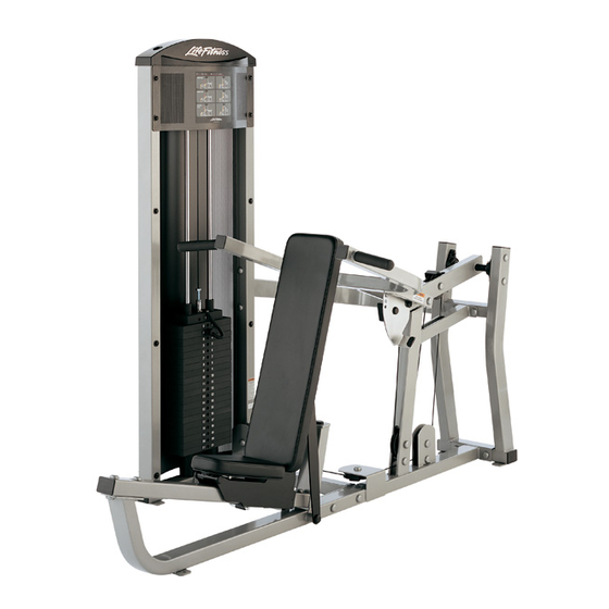
FIT SERIES MULTI PRESS ASSEMBLY INSTRUCTIONS Part # 7489101 Revision:5/06/03 Rev A. -
Page 2: Parts List
PARTS LIST DESCRIPTION PART # DESCRIPTION PART # TOWER ACU04-1647 ACU08-0078 3/8 X 3/4” FLANGE SPACER 3-1/2 X 1” CABLE CLIP ACU02-0078 ACU08-0077 3/8 X 1” FLANGE SPACER SEAT PAD SUPPORT ACU04-1361 ACUDA1C03802516NU 3/8 X 25mm BOLT PRESS ARM ACU04-1338 3/8 X 32mm BOLT ACUDA1C03803216NU PIVOT ARM... - Page 3 34 3/8 X 25mm BOLT 3/8” LOW HEIGHT LOCK 35 3/8 X 32mm BOLT 3/8” SAE WASHER 36 3/8 X 43mm BOLT 37 3/8 X 43mm BOLT W/NYLOCK 3/8” BLACK FLAT WASHER 38 3/8 X 61mm BOLT RH CAP (WHITE/PLATINUM/BLACK) 39 3/8 X 67mm BOLT 40 3/8 X 70mm BOLT WASHER...
- Page 4 45 3/8 X 25mm BUTTON HEAD BOLT 3/8” FLAT WASHER 46 3/8 X 76mm BUTTON HEAD BOLT 3/8 X 1/2” FLANGE SPACER 47 3/8 X 90mm BUTTON HEAD BOLT 3/8 X 3/4” FLANGE SPACER 3/8” ACORN NUT 3/8 X 1” FLANGE SPACER Bolt Length Ruler NOTE: BOLT LENGTH IS MEASURED FROM THE UNDERSIDE OF THE HEAD OF THE BOLT.
- Page 5 39 3/8 X 67mm 3/8 X 67mm 39 42 3/8 X 90mm 3/8 X 90mm 42 FIGURE 1 STEP 1: • LOOSELY assemble the BASE (13) to the PRESS FRAME (8) and TOWER (1) using eight RH CAPS (53), four 3/8 X 90mm BOLTS (42), eight 3/8”...
- Page 6 TIGHTEN! TIGHTEN! TIGHTEN! FIGURE 2 STEP 2: • Securely tighten all loose frame connections made to this point, then proceed to snap RH CAPS (53) over the RH WASHERS (51) on all tightened connections.
- Page 7 SPRING PIN FIGURE 3 STEP 3: • Pull back on the SPRING PIN and slide the SEAT ADJUST (6) over the SLIDE TUBE (12) as shown in FIGURE 3. • Assemble the SLIDE TUBE (12) to the PRESS FRAME (8) as shown in FIGURE 3. 34 3/8 X 25mm 3/8 X 61mm 38 3/8 X 67mm 39...
- Page 8 FIGURE 5 STEP 5: • Insert one 5-1/2” PIVOT SHAFT (27) into the PRESS FRAME (8) and one 5-1/2” PIVOT SHAFT (27) into the BACK PAD SUPPORT (7) as shown in FIGURE 5. 52 BLACK 44 3/8 X 164mm 43 3/8 X 106mm FIGURE 6 52 BLACK STEP 6:...
- Page 9 STEP 7: FIGURE 7 • SECURELY assemble the BACK PAD (16) to the BACK PAD SUPPORT (7) using two BLACK RH CAPS (52), two 3/8 X 73mm BOLTS (41), two 3/8” SAE WASHERS (50) and two 3/8” RH WASHERS (51) as shown in FIG- URE 7.
- Page 10 TIGHTEN! FIGURE 9 STEP 9: • SECURELY assemble the PIVOT ARM (5) to the REAR UPRIGHT (15) using four previously inserted 3/8 X 76mm BUTTON HEAD BOLTS (46), four RH WASHERS (51), four 3/8” SAE WASHERS (50), four 3/8” LOW HEIGHT LOCK NUTS (49) and four RH CAPS (53) as shown in FIGURE 9.
- Page 11 FIGURE 11 3/8 X 73mm 41 52BLACK 39 3/8 X 67mm STEP 11: • Finish assembling the PRESS ARM ADJUST PLATE (10) to the PIVOT ARM (5) using two RH CAPS (53), two BLACK RH CAPS (52), one 3/8 X 67mm BOLT (39), one 3/8 X 73mm BOLT (41), four 3/8” SAE WASHERS (50), four 3/8” RH WASHERS (51), one 3/8 X 3/4”...
- Page 12 FIGURE 12 37 3/8 X 43mm W/LOCTITE STEP 12: • SECURELY assemble the PRESS ARM (4) to the PIVOT ARM (5) using two RH CAPS (53), two 3/8 X 43mm BOLTS W/LOCTITE (37), two 3/8” SAE WASHERS (50) and two 3/8” RH WASHERS (51) as shown in FIGURE 12.
- Page 13 FIGURE 13 52 BLACK 3/8 X 70mm 40 39 3/8 X 67mm 3/8 X 61mm 38 STEP 13: • Route the MULTI PRESS CABLE (54) through the PRESS FRAME (8) and SECURELY assemble one 4-1/2” PULLEY (19) to the PRESS FRAME (8) using four RH CAPS (53), one 3/8 X 67mm BOLT (39), one 3/8 X 61mm BOLT (38), four 3/8” SAE WASHERS (50), four 3/8”...
- Page 14 3/8 X 43mm 36 36 3/8 X 43mm 3/8 X 43mm 36 52 BLACK FIGURE 14 STEP 14: • Route the MULTI PRESS CABLE (54) through the vertical bracket on the PRESS FRAME (8) and SECURELY assemble one 4-1/2” PULLEY (19) to the bracket using four RH CAPS (53), two 3/8 X 43mm BOLTS (36), four 3/8” SAE WASHERS (50), four 3/8” RH WASHERS (51) and two 3/8”...
- Page 15 39 3/8 X 67mm FIGURE 15 STEP 15: • Route the MULTI PRESS CABLE (54) through the TOWER (1) and SECURELY assemble two 4-1/2” PULLEYS (19) to the TOWER (1) using two 3/8 X 67mm BOLTS (39), four 3/8 X 1/2” FLANGE SPACERS (31) and two 3/8” LOW HEIGHT LOCK NUTS (49) as shown in FIGURE 15.
- Page 16 LUBRICATION NOTE: When finished assembling the Weight Stack, open the lube Pack provided with this unit and apply a thin film of Lubricant around the first 2 to 3 inches of each Guide Rod above the Head Plate Assembly. After the cables are installed, use of the ma- chine will spread the lubricant over the length of the Guide Rods and into the...
- Page 17 39 3/8 X 67mm TIGHTEN! FIGURE 17 STEP 17: • Route the threaded end of the MULTI PRESS CABLE (54) through the GUIDE ROD SUPPORT (9) and SECURELY assemble the GUIDE ROD SUPPORT (9) to the TOWER (1) using two 3/8 X 67mm BOLTS (39), four 3/8” FLAT WASHERS (60) and two 3/8” LOW HEIGHT LOCK NUTS (49) as shown in FIGURE 17.
- Page 18 ADJUSTMENT FIGURE 18 STEP 18: • Adjustments can be made in the above locations to set the correct amount of tension in the cables. • If upon completion of assembly, the HEAD PLATE (24) does not sit on top of the first WEIGHT PLATE (22), push the HEAD PLATE (24) down, insert the WEIGHT STACK PIN (25) and perform several repetitions.
- Page 19 BOLTS (47), twenty 3/8” BLACK FLAT WASHERS (48) and ten 3/8” ACORN NUTS (59) as shown above. Thank you for purchasing the LifeFitness FIT SERIES MULTI PRESS. If unsure of proper use of equip- ment, call your local LifeFitness distributor or call the LifeFitness customer service department at...
-
Page 20: Warranty Information
• Lube the Guide Rods. Apply the lubricant to a cotton cloth, then run the cotton cloth up and down the guide rods as needed. Do not spray lubricant directly on the Guide Rods. Thank you for purchasing the LifeFitness FIT SERIES MULTI PRESS. If unsure of proper use of equip- ment, call your local LifeFitness distributor or call the LifeFitness customer service department at...
Need help?
Do you have a question about the FIT SERIES MULTI PRESS and is the answer not in the manual?
Questions and answers