
Related Manuals for Motic PA43


Summary of Contents for Motic PA43
- Page 1 PA43 Operation Manual If the equipment is used in a manner not specified by the manufacturer, the protection provided by the Note equipment may be impaired. WWW.MOTIC.COM MOTIC HONG KONG LIMITED...
- Page 2 This instruction Manual has been prepared for users of the Motic PA43 Upright Microscope. For your own safety, read this manual carefully and thoroughly before using the product. Do not discard this manual. Always keep it near the product for easy reference.
-
Page 3: Table Of Contents
Instrument safety, FCC and EMC conformity Transporting, unpacking, storage of the Instrument Instrument Disposal Use of the Instrument Intended use of the Microscope Instrument warranty Nomenclature PA43 Setting up the Instrument Operating environment Assembling the Microscope Verifying input voltage Illumination 4.2.1 Halogen bulb 4.2.2 LED... - Page 4 Kohler Illumination alignment procedure: Centering the Condenser Kohler Illumination alignment procedure: Setting the Aperture Iris Diaphragm Brightness and contrast adjustment Illumination brightness adjustment 5.7.1 PA43 with light manager Standby mode 6. Photomicrographic Procedure 7. Using Oil Immersion Objectives 8. Care and Maintenance...
-
Page 5: General Notes On Instrument Safety
Please familiarize yourself with this Operation Manual before starting to use the Instrument. In case additional information or support is needed, please contact Motic after sales Service. To ensure safe operation and optimal function of the Instrument, strictly observe the precautions and warnings given in this Operation manual. -
Page 6: Instrument Safety, Fcc And Emc Conformity
UL, CE, FCC, EMC “Safety of equipment used for measurement control and laboratory use” PA43 Microscope Series Products are in conformity with the requirements of the CE Directive 98/79/EC Annex 1 and carries the CE mark accordingly. Conform to Class B Noise immunity is in compliance with EN 61326 and EMC and... -
Page 7: Transporting, Unpacking, Storage Of The Instrument
Please always observe the following safety notes when using the microscope: Motic cannot assume any liability for other applications then the intended use, including the included modules and components. This includes to service or repair work that is not carried out by authorized Motic service personnel. - Page 8 The operation of the instrument in explosion-risk environments is not allowed. Immersion Oil can be harmful. Please only use Motic immersion Oil and follow the safety Instructions given. Immersion oil is to be used for Microscope application only! Please avoid...
-
Page 9: Intended Use Of The Microscope
If possible defects Motic must be notified immediately and steps be taken to minimize damage. ● If notified of such a defect Motic will evaluate the defect and if within warrant, rectify it at his discretion, either by repairing the instrument or by delivering a replacement. -
Page 10: Nomenclature
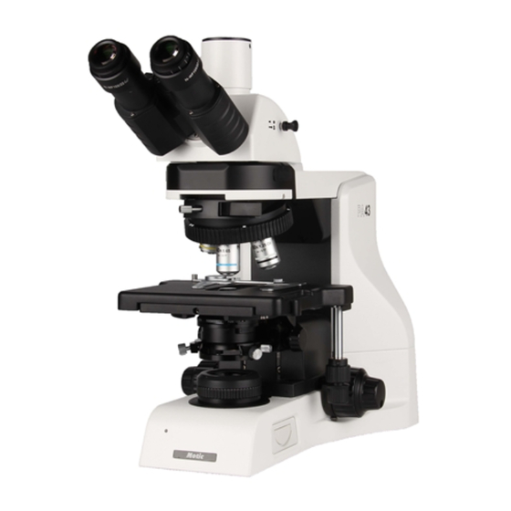
2. NOMENCLATURE 2.1 PA43 (Fig. 1) - Page 11 (Fig. 2)
-
Page 12: Setting Up The Instrument
Air pressure of 75kPa to 106 kPa ● Avoid frost, dew, percolating water, and rain. Please familiarize yourself with the instructions given in this Operation Manual. In case of unresolved questions, please contact Motic after sales Service or consult Motic Web services for further instructions. -
Page 13: Assembling The Microscope
4. ASSEMBLING THE MICROSCOPE 4.1 Verifying input voltage ● The automatic voltage selection works with a broad range of settings, please check the power rating of your country is admitted before the use of the Instrument under chapter specification. However, always use a power cord that is rated for the voltage used in your area and that has been approved to meet local safety standards. -
Page 14: Objectives
4.4 Objectives ● Lower the stage completely. Screw the objectives into the revolving nosepiece so that clockwise rotation of the nosepiece brings the next higher magnification objective into position. (Fig. 4) 4.5 Condenser ● Raise the stage by turning the coarse focus knob. ●... -
Page 15: Eyepiece Tube
4.6 Eyepiece tube ● Loosen the eyepiece clamp screw (Fig. 6-2). Insert the round dovetail mount on the eyepiece tube into the round dovetail mount on the microscope arm (Fig. 6-1). Tighten the eyepiece tube clamp screw to secure the eyepiece tube in place. (Fig. 6-2) (Fig. -
Page 16: Filters
4.8 Filters ● Remove the collector cover (Fig. 8-1) and place the filter in the filter holder located around the field lens (Fig. 8-2), screw back the collector cover (Fig. 8-1), taking care that dust, dirt and fingerprints do not get on the filter and the field lens. (Fig. -
Page 17: Installing The Polarzier With The Filter Holder
4.9 Installing the Polarzier with the filter holder ● Remove the collector cover (Fig. 9-1) and place the polarzier in the filter holder located around the field lens (Fig. 9-2), taking care that dust, dirt and fingerprints do not get on the filter and the field lens. -
Page 18: Installing The Analyzer With The Analyzer Slot
4.10 Installing the Analyzer with the analyzer slot ● Remove the dust cover (Fig. 10-1) and insert the Analyzer into the analyzer slot. (Fig. 10-2) (Fig. 10-1) (Fig. 10-2) (Fig. 10-3) 4.11 Power cord ● Connect the socket of the of the power cord to the AC inlet on the rear of the base of the microscope. -
Page 19: Usage Of Microscope Components
5. USAGE OF MICROSCOPE COMPONENTS 5.1 Focusing Block 5.1.1 Replacing the Fine Focus Knob ● The fine focus knob (Fig. 11) is designed detachable to prevent interference with hand during manipulation of the fine adjustment knob or XY-axis knob. ● Usually attach the knob on the opposite side to the XY-axis knob. -
Page 20: Pre-Focusing Lever
This adjustment will enable the user to observe the specimen with both eyes ● Depending on the working environment and its demands, the PA43 has a solution. Each eyepiece tube allows a 360°swiveling movement (Fig. 14-1) as well as a flexible adjustment of the interpupillary distance between 48 and 75mm. -
Page 21: Diopter Adjustment
360°swiveling movement Butterfly movement (Fig. 14-1) (Fig. 14-2) 5.3 Diopter adjustment Every human eye is different, to adjust the Instrument to best performance adjustment can be necessary. ● Set the diopter on both eyepieces to the “0” position. ● Change to 10x Magnification and the image of the specimen into focus using one eye only. ●... -
Page 22: Selecting The Light Path Of The Trinocular Tube
(Fig. 15) 5.3.1 Selecting the Light Path of the Trinocular Tube ● Slide the light path selector lever to select the desired light path. (Fig. 16) Light Path Selector Lever Indication Light Path Ratio Pushed-in position Binocular 100% Pulled-out position TV &... -
Page 23: Kohler Illumination Alignment Procedure: Centering The Condenser
5.4 Kohler Illumination alignment procedure: Centering the Condenser ● Turn the condenser height adjustment knob (Fig. 17-1) to raise the condenser to its upper limit. ● Focus on the specimen using the 10x objectives. ● Rotate the field iris diaphragm ring (Fig. 17-1) in the direction of the clockwise so that the diaphragm image comes inside the field of view. -
Page 24: Kohler Illumination Alignment Procedure: Setting The Aperture Iris Diaphragm
5.5 Kohler Illumination alignment procedure: Setting the Aperture Iris Diaphragm ● The aperture iris diaphragm determines the numerical aperture of the illumination system. It has an effect of adjusting image resolution and contrast. ● Since the contrast of microscope specimens is ordinarily low, setting the condenser aperture iris diaphragm to between 70 and 80% of the NA of the objectives in use is usually recommended. -
Page 25: Illumination Brightness Adjustment
5.7 Illumination brightness adjustment 5.7.1 PA43 with light manager ● To adjust the brightness, turn the brightness adjustment knob (Fig. 21-2) and observe change in brightness until the desired level has been reached. ● If the illumination has not been changed for 3 seconds, the actual value will be stored for this objective magnification. -
Page 26: Photomicrographic Procedure
6. PHOTOMICROGRAPHIC PROCEDURE ● To ensure vibration free operation, set the microscope on a sturdy vibration free table or a bench with a vibration proof device. ● Pull the optical path selection lever of the trinocular eyepiece tube all of the way out to the limit, the ratio of light entering the observation tube and standard phototube will be 20:80. -
Page 27: Using Oil Immersion Objectives
Oil immersion objectives are labelled with the additional engraving “Oil” and are to be immersed in oil between the specimen and the front of the objective. ● The immersion oil supplied by Motic is synthetic, non-fluorescing and non-resining oil, with a refractive index of 1.515. ●... -
Page 28: Care And Maintenance
Store the objectives, eyepieces and filters in a container or desiccators with drying agent. ● Proper handling of the microscope will ensure years of trouble free service. ● If repair becomes necessary, please contact your Motic agency or our Technical Service direct. -
Page 29: Bulb Replacement
Note: ● If equipment is used in a manner not specified by the manufacturer, the warranty may be void. ● To avoid getting wet, do not use the microscope near water. 8.5 Bulb replacement The lamp and the lamp drawer become very hot during and after a period of operation. Risk of burn –... -
Page 30: Electrical Specifications
(Fig. 22-3) (Fig. 22-4) 8.5.2 Electrical Specifications: Input: AC100-240V~, 50/60Hz, 1.5A (max) Reflected Lamp: 30W Halogen or 3W LED LED module, high color temperature: 5500K~ 6000K LED module, low color temperature: 3000K ~ 3500K Shifting of Instrument Caution: To avoid the risk of electric shock, this equipment must only be connected to a supply main with protective earth. -
Page 31: Specification
9. SPECIFICATION Model PA43 Optical System Colour Corrected Infinity Optical System (CCIS®) Trinocular - Light distribution (100:0 / 20:80), Observation Tube Incline angle 30° Wide-Field WF10X/22, Diopter adjustable +/- 5 dpt Eyepieces (option) Revolving Nosepiece 5-position nosepiece Plan UC 4X... -
Page 32: Troubleshooting Table
10. TROUBLESHOOTING TABLE As you use your microscope, you may occasionally experience a problem. The troubleshooting table below contains the majority of frequently encountered problems and the possible causes. 10.1 Optical Problem Possible Cause Lamp not installed properly Lamp not centred Diffuser is in intermediate position Condenser not mounted correctly Condenser is not centred... -
Page 33: Electrical
Stage installed on inclined plane Unequal focus Specimen holder not fixed securely on stage Specimen not secured in position Lamp voltage is set too low Image tinged yellow Blue filter is not being us Slide is upside down Focusing is not possible with high magnification objectives Cover glass is too thick Slide is upside down... -
Page 34: Selection Of The Power Supply Cord
Motic Instruments are certified and tested for safety and environmental conformity. Only power supply cords which are conform with below listed certification marks and countries are applicable. CAUTION : Do not use non-approved power cord for Motic products, Motic can no longer warrant the electrical safety of the equipment. - Page 35 Table 2 HAR Flexible Cord Approval Organizations And Cordage Harmonization Marking Methods Alternative Marking Printed or Embossed Utilizing Black-Red-Yellow Harmonization Marking (May Thred (Length of color Approval Organization be located on jacket or section in mm) insulation of internal wiring) Black Yellow Comite Electrotechnique Belge...
-
Page 36: Microscope Terminology
MICROSCOPE TERMINOLOGY Abbe Condenser Magnification A two-lens sub-stage condenser located below The number of times by which the size of the the stage of a microscope and functions to collect image exceeds the original object. Lateral light and direct it onto the object being examined. magnification is usually meant. - Page 37 Diopter adjustment Resolving Power The adjustment of the eyepiece of an instrument A measure of an optical system's ability to to provide accommodation for the eyesight produce an image which separates two points or differences of individual observers. parallel lines on the object. Depth of Focus Resolution The axial depth of the space on both sides of the...
- Page 38 Fax: 86-0592-562 7855 © 2002-2022 Motic China Group Co., Ltd. All rights reserved. Motic is a registered trademark and service mark of Motic China Group Co., Ltd. Microsoft Windows logo is a registered trademark of Microsoft Corporation. All other trademarks are the property of their respective owners.
Need help?
Do you have a question about the PA43 and is the answer not in the manual?
Questions and answers