Table of Contents
Advertisement
Quick Links
Motic PA53MET User Manual
Version 1.0.1
IMPORTANT NOTICE
This product may malfunction due to electromagnetic waves caused by portable personal telephone,
transceivers, radio-controlled toys, etc. Be sure to avoid having the above objects, which affect the
normal operation of the product, brought near the product. The information in this publication has been
carefully checked and is believed to be entirely accurate at the time of publication. MOTIC assumes no
responsibility, however, for possible errors or omissions, or for any consequences resulting from the use
of the information contained herein.
MOTIC reserves the right to make changes in its products or product specifications at any time and
without prior notices, and is not required to update this documentation to reflect such changes.
©2018 Motic China Group Co., Ltd.
All rights are reserved.
Under copyright laws, this manual may not be copied, in whole or in part, without the prior written
consent of Motic China Group Co., Ltd.
1
Advertisement
Table of Contents

Related Manuals for Motic PA53MET


Summary of Contents for Motic PA53MET
- Page 1 The information in this publication has been carefully checked and is believed to be entirely accurate at the time of publication. MOTIC assumes no responsibility, however, for possible errors or omissions, or for any consequences resulting from the use of the information contained herein.
-
Page 2: Table Of Contents
Base 8.1.1 Voltage Indication and Switch 8.1.2 Turn ON/OFF Power saving function 8.1.3 Turn ON/OFF Intelligent Light function 8.1.4 Using the built-in Filters [PA53MET-T, PA53MET-BD-T] Focusing Block 8.2.1 Replacing the Fine Adjustment Knob 8.2.2 Adjusting the Coarse Adjustment Knob Tension 8.2.3 Pre-focusing Lever... - Page 3 Installing the Bulb 11.2.2 Attaching the Lamp housing 11.2.3 Attaching the Condenser [PA53MET-T, PA53MET-BD-T] 11.2.4 Attaching the Stage 11.2.5 Attaching the Observation Tube 11.2.6 Attaching the Eyepiece 11.2.7 Attaching the Control Box and Control Pad [PA53MET-3D, PA53MET-BD-3D] 11.2.8 Attaching the Computer...
-
Page 4: Safety Information
1. SAFETY INFORMATION 1.1 Introduction Safety is everyone’s responsibility. The safe use of this equipment is largely dependent upon the installer, user, operator, and maintainer. It is imperative that personnel study and become familiar with this entire manual before attempting to install use, clean, service or adjust this equipment and any associated accessories. -
Page 5: Safety Symbols
1.2 Safety Symbols PA53MET Upright Compound Microscope The International Electro technical Commission (IEC) has established a set of symbols. The symbols are shown as below. This applies only to the instrument that has the certification symbol printed explicitly on the product label or sticker. -
Page 6: Environment Factors
1.3 Environment factors Avoid the following environments for operation or storage: ● Where the equipment is exposed to water vapor. Don’t operate an equipment with a wet hand. For indoor use only ● Where the equipment is exposed to direct sunlight. ●... -
Page 7: Safety Precautions
The equipment must be operated only by, or under direct supervision of a properly trained and qualified person. ● Modifications of this equipment may only be carried out by MOTIC’s service technicians or other authorized persons. ● Customer maintenance of this equipment may only be performed as stated in the User’s Manual and Service Manual. - Page 8 ● Before every operation, visually check the equipment for exterior mechanical damage(s) and for proper function. ● Immediately turn off and unplug any equipment that gives off smoke, sparks, strange noises, or odors. ● After the equipment has been used in an observation of a specimen that is accompanied with a potential of infection, clean the parts coming in contact with the specimen to prevent infection.
-
Page 9: Introduction
2. INTRODUCTION 2.1 Indication for use (Intended use) This instrument has been designed to be used to observe magnified images of specimens in routine and research applications. Do not use this instrument for any purpose other than its intended use. 2.2 Classification ●... -
Page 10: Operating Condition
3. OPERATING CONDITION ● As long as the device is in its original package it can be exposed to the following environmental conditions for up to 15 weeks for shipping and storage without risk of damage: Temperature range: from -40°C to +70°C; Relative humidity range: below 100%;... -
Page 11: Getting Ready
4. GETTING READY ● A microscope is a precision instrument. Handle it with care and avoid subjecting it to sudden or severe impact. ● When moving the microscope, first remove the specimens, eyepieces, and filters so that they will not drop. Also remove other modules (e.g. lamp housing, stage) for decreasing system weight. Then securely grasp the microscope by the rear of arms and the base. -
Page 12: Maintenance And Storage
5. MAINTENANCE AND STORAGE ● To clean the lenses and other glass components, simply blow dirty away using a commercially available blower and wipe gently using a piece of cleaning paper (or clean gauze). If a lens is stained with fingerprints or oil smudges, wipe it gauze slightly moistened with commercially available absolute alcohol. -
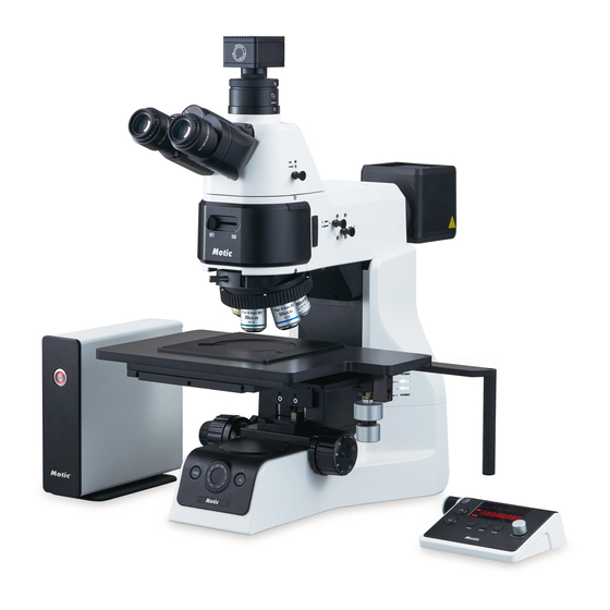
Page 13: Nomenclature
6. NOMENCLATURE... - Page 15 (Control box and control pad are provided PA53MET-3D, PA53MET-BD-3D only.)
-
Page 16: Observation Procedure
7. OBSERVATION PROCEDURE 7.1 Preparation ● If you have not assembled the microscope yet, please read “Chapter 11. Assembly”. ● For the reflected light observation, please refer its operation manual. 7.2 Procedure ● Set the main switch to T (ON). ●... -
Page 18: Operation
8. OPERATION 8.1 Base 8.1.1 Voltage Indication and Switch ● Push the brightness adjustment knob to switch transmitted / reflected light illumination. ● Turn the brightness adjustment knob counter-clockwise to increase the voltage and make illumination brighter, and vice versa. ●... -
Page 19: Turn On/Off Intelligent Light Function
To set new preset brightness, press IL button long while IL indicator LED turns on. Fig. 3 8.1.4 Using the built-in Filters [PA53MET-T, PA53MET-BD-T] ● Each of filter switch can engaged into the light path by push up the switch. Push down the switch disengages the filter from light path. -
Page 20: Focusing Block
8.2 Focusing Block 8.2.1 Replacing the Fine Adjustment Knob ● The fine adjustment knob is designed detachable to prevent interference with hand during manipulation of the fine adjustment knob or XY-axis knob. ● Usually attach the knob on the opposite side to the XY-axis knob. ●... -
Page 21: Pre-Focusing Lever
8.2.3 Pre-focusing Lever ● The pre-focusing lever ensures that the objectives does not come in contact with the specimen and simplifies focusing. ● After focusing on the specimen with the coarse adjustment knob, turn this lever clockwise and lock. The upper limit on coarse adjustment movement is set at the locked position. -
Page 22: Observation Tube
8.4 Observation Tube 8.4.1 Adjusting the Interpupillar Distance ● While looking through the eyepieces, adjust for binocular vision until the left and right fields of view coincide completely. ● The Index dot indicates the interpupillary distance. Fig. 9 8.4.2 Adjusting the Diopter ●... -
Page 23: Using The Eye Shades
8.4.3 Using the Eye Shades ● When wearing eyeglasses, use with the eyeshades in the normal, folded-down position. This will prevent the eyeglasses from being scratched. ● When not wearing eyeglasses, extend the folded eye shades in direction of the arrow to prevent extraneous light from entering between the eyepieces and eyes. -
Page 24: Condenser [Pa53Met-T, Pa53Met-Bd-T]
8.5 Condenser [PA53MET-T, PA53MET-BD-T] 8.5.1 Centering the Condenser ● Turn the condenser height adjustment knob to raise the condenser to its upper limit. ● Focus on the specimen using the 10x objectives. ● Rotate the field iris diaphragm ring in the direction of the clockwise so that the diaphragm image comes inside the field of view. -
Page 25: Setting The Aperture Iris Diaphragm
8.5.2 Setting the Aperture Iris Diaphragm ● The aperture iris diaphragm determines the numerical aperture of the illumination system. It has an effect of adjusting image resolution and contrast. ● Since the contrast of microscope specimens is ordinarily low, setting the condenser aperture iris diaphragm to between 70 and 80% of the NA of the objectives in use is usually recommended. -
Page 26: Control Pad [Pa53Met-3D, Pa53Met-Bd-3D]
8.6 Control pad [PA53MET-3D, PA53MET-BD-3D] 8.6.1 General function ● Push the focus adjustment button to control height of stage. ● Rotate the fine focus adjustment knob to control height of stage precisely. ● Push the focus adjustment knob to change precision of control. -
Page 27: Safety Function
Fig. 19 8.7 Linking Motic Analysis 8.7.1 Computer Control ● Some parameter can be controlled by using Motic Analysis program. ● Run Motic Analysis program in computer. ● Select “Microscope - MOTIC Upright” in menu bar. -
Page 28: Troubleshooting Guide
Under certain conditions, performance of the microscope may be adversely affected by factors other than defects. If problems occur, Please review the following list and take remedial action as needed. If you cannot solve the problem after checking the entire list, please contact MOTIC 9.1 Electrical system... - Page 29 Nosepiece is not rotated to a Rotate the nosepiece to a click click stop position. stop position. Condenser is not attached Re-attach it. properly. Condenser is not centered Center the condenser. properly. Field diaphragm is stopped Open to a suitable size. down too far.
-
Page 30: Observation Tube
9.3 Observation Tube Problem Cause Remedy Interpupillary distance is not Adjust the interpupillary correct. distance. Eyepiece diopter is not 1. Field of view does not match Adjust the diopter. adjusted. with both eyes Use the same type Different eyepiece is used on (magnification, field number) on left and right. -
Page 31: Specifications
10. SPECIFICATIONS 10.1 Body unit PA53MET PA53MET-3D PA53MET-T PA53MET-BD PA53MET-BD-3D PA53MET-BD-T Optical System Colour Corrected Infinity Optical System (CCIS®) Reflected / Reflected / Illumination Reflected Reflected Reflected Reflected Transmitted Transmitted Observation Tube Binocular Erect type (F.N 25), 20° inclined (Optional) Trinocular Erect type (F.N 25), 20°... -
Page 32: Module Of Pa53Met
6x6” stage, 6x6” stage, 8” wafer stage, 12” wafer stage Optional Dimension Approx. 246(W) x 572(D) x 514(H) Weight Approx. 19kg 10.2 3D module of PA53MET Item PA53MET-3D, PA53MET-BD-3D 1. mechanism High-resolution 5-phases stepping motor Long cross-roller guide system 2. Stroke Distance 30mm 0.01μm... -
Page 33: Suitable Objectives
10.3 Suitable Objectives ● The following list shows the optical characteristic of Plan Fluor objectives. ● Plan Fluor objective is not suitable for phase contrast, and has no iris diaphragm or correction collar. Objective Cover glass Field of view (mm) Magnification Lens (mm) -
Page 34: Assembly
11. ASSEMBLY 11.1 Assembly Diagram ● The diagram below shows the sequence of assembly of the various modules. ● When assembling the microscope, make sure that all parts are free of dust and dirt, and avoid scratching any parts or touching glass surfaces. ●... -
Page 35: Detailed Assembly Procedures
11.2 Detailed Assembly Procedures 11.2.1 Installing the Bulb WARNING The bulb, the lamp socket and areas near these will be extremely hot during and right after use. Set the main switch off; disconnect the power cord from the wall outlet, then wait until lamp housing has cooled down before replacing the bulb with a new of the designated type. -
Page 36: Attaching The Lamp Housing
11.2.2 Attaching the Lamp housing WARNING The bulb, the lamp socket and areas near these will be extremely hot during and right after use. Set the main switch off; disconnect the power cord from the wall outlet, then wait until lamp housing has cooled down before removing the Lamp housing. -
Page 37: Attaching The Condenser [Pa53Met-T, Pa53Met-Bd-T]
11.2.3 Attaching the Condenser [PA53MET-T, PA53MET-BD-T] ● Turn the coarse adjustment knob to raise the stage to its upper limit. ● Turn the condenser height adjustment knob to lower the condenser holder to its lowest position. ● Fully loosen the condenser clamping knob. -
Page 38: Attaching The Observation Tube
11.2.5 Attaching the Observation Tube ● Fully loosen the observation tube clamp screw with provided Allen screwdriver. ● Place the observation tube on the top of illuminator and tighten the observation tube clamp screw . Fig. 26 11.2.6 Attaching the Eyepiece NOTE Attach eyepieces of the same magnification and of the same field number to the left and the right eyes. -
Page 39: Attaching The Control Box And Control Pad [Pa53Met-3D, Pa53Met-Bd-3D]
● Connect controlpad connecter withprovided 6pin cable and fasten it ● Connect controlbox connector withanother end of 12pin cable and fasten it. ● Connect Motic Analysis port and computer with RS232C cable when using Motic Analysis program. Fig. 28... -
Page 40: Attaching The Computer
11.2.8 Attaching the Computer ● Connect Motic Analysis port and computer with RS232C cable when using Analysis program. Fig. 29...
Need help?
Do you have a question about the PA53MET and is the answer not in the manual?
Questions and answers