
Related Manuals for Ampac LoopSense EN54.2


Summary of Contents for Ampac LoopSense EN54.2
- Page 1 Fire detection and evacuation solutions that save lives. LoopSense Fire Alarm Control Panel (EN54.2 & 4) User Manual MAN1572-7...
- Page 2 MAN1572-7 Responding to a Fire Access Level 1 Indicators Controls DELAY ACTIVE SILENCE BUZZER OVERRIDE FIRE ZONE 1 The OVERRIDE key is pressed to override any delays to outputs Access Level 2 EVACUATE The EVACUATE key is pressed to turn ON all alarm devices. ALARMS SILENCE RESOUND...
-
Page 3: Table Of Contents
MAN1572-7 Contents About This Manual ..........................5 Introduction ........................5 Introduction ............................5 System Overview ......................5 Front Panel Control Card ........................6 Levels of Access ......................6 3.1.1 Passwords ........................7 3.1.2 Misplaced Password ....................... 7 System Controls & Indicators..................8 Liquid Crystal Display.....................12 Displayed Conditional Responses ......................13 Normal Condition ......................13... - Page 4 MAN1572-7 7.3.1 Menu->Events->Print ....................33 7.3.2 Menu->Events->Delete....................33 7.3.3 Menu->Events->Goto ....................33 Menu > Tools ........................34 Menu > Setup ........................35 7.5.1 Menu->Setup->Date and Time ..................35 7.5.2 Menu->Setup->Day/Night .....................35 7.5.3 Menu->Setup->Earth Monitoring ..................36 7.5.4 Menu->Setup->Passwords .....................36 Menu > Programming....................37 7.6.1 Menu->Programming->Zone ..................38 7.6.2 Menu->Programming->Device ..................39 7.6.3 Menu->Programming->Panel ..................44 7.6.4...
-
Page 5: About This Manual
MAN1572-7 1 About This Manual 1.1 Introduction This manual contains all the information required to operate the LoopSense Fire Alarm Control Panel (FACP). The first step in becoming a proficient operator is to be familiar with and understand the “Menu Structure”... -
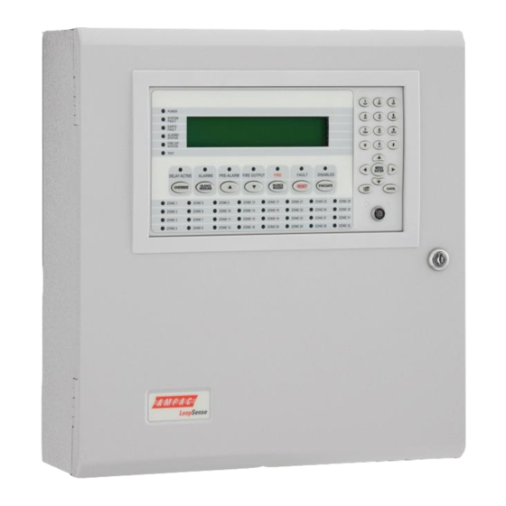
Page 6: Front Panel Control Card
MAN1572-7 3 Front Panel Control Card The Front Panel Control Card interfaces to the Main Control Board and supports; ➢ all the controls and functional indicators ➢ the FACP Reset ➢ Menu system control ➢ Serial or Parallel Printer port Figure 1: Front Panel Layout 3.1 Levels of Access The FACP supports three levels of access. -
Page 7: Passwords
2. The panel responds by displaying a unique 10 digit key 3. Contact the local Ampac Service Centre and they will issue a temporary password 4. The temporary password is entered, and access is gained to the panel. The operator can now access the password menu and set the passwords up as appropriate for the installation The temporary password will be deleted, the next time a password is successfully entered into the FACP. -
Page 8: System Controls & Indicators
MAN1572-7 3.2 System Controls & Indicators The front panel has fourteen push button controls, a key switch and an alpha numeric keypad. Controls, Normal – Enabled (Key Switch) CONTROLS ENABLE KEY SWITCH. = OFF, = ON If the key switch is in the OFF position (access level 1), then the OVERRIDE, PREVIOUS, NEXT, SILENCE BUZZER and LAMP TEST controls are active. - Page 9 MAN1572-7 able attribute set shall respond to silence/resound. Silenced alarm devices shall automatically resound on the occurrence of a new fire event. Pre-Alarm / Previous Available at access level 1 and above PRE-ALARM Pre-alarm – Illuminated when one or more devices are in the pre-alarm condition and not disabled Previous Momentary push button.
- Page 10 MAN1572-7 Fault / Reset Available at access level 2 and above FAULT RESET Fault – Indicator illuminated when there are one or more faults on the system. ➢ Fault with loop devices ➢ Fault with the loops ➢ Fault with the fire alarm routing equipment or fault warning routing equipment ➢...
- Page 11 MAN1572-7 MENU / ENTER, 0-9, *, #, CANCEL and ◄▼▲► - Provides a means for entering the menu system, and carrying out interrogation, control and programming activities POWER Illuminated to show the presence of mains power and flashes when the mains have failed SYSTEM FAULT Illuminated when the FACP is unable to provide mandatory functions.
-
Page 12: Liquid Crystal Display
MAN1572-7 3.3 Liquid Crystal Display LCD is used to display abnormal conditions and for interrogation, control and programming activities. When the FACP is in its normal state a default screen is displayed. Backlight (refer to EN54.2:1997: 12.8.5): The associated backlight is energised; ➢... -
Page 13: Displayed Conditional Responses
MAN1572-7 4 Displayed Conditional Responses 4.1 Normal Condition The POWER LED is illuminated meaning the mains voltage is present, and all other indicators are off. The 4 x 40 LCD will display the; DD/MM/YYYY HH:MM ACCESS LEVEL 1 current date, time and access level on line 1 USER DESCRIPTOR LINE 1 configured user descriptors of customer/site USER DESCRIPTOR LINE 2... -
Page 14: Fire Condition
MAN1572-7 4.2 Fire Condition If an input or device is activated and it is configured to generate a fire condition the FACP responds to the fire as follows: ➢ Common FIRE LED will turn on steady ➢ Assigned zone fire LED will illuminate ➢... -
Page 15: Fault Condition
MAN1572-7 The FACP also displays fires in Device mode. Pressing the “DEVICE►” forward button allows the panel to display all the devices or inputs on the system that are in fire. <point location> FIRE <point descriptor> <type> <date> <time> CONTROL* FIRE XXX OF XXX ◄ZONE Pressing the... -
Page 16: System Fault Condition
MAN1572-7 4.3.1 System Fault Condition (EN54.2:1997: 8.5, 13.4, 13.6, 13.7a) The System Fault condition is activated if the FACP fails to provide mandatory functions. When a system fault condition occurs, the panel buzzer, System Fault and General Fault indicators shall be activated. Mandatory functions failures include: ➢... -
Page 17: Pre-Alarm Condition
MAN1572-7 If the panel is forced into boot mode upon a software exception (mandatory functions failure 5 above), a screen such as the following shall be presented !EXCEPTION! – PRESS * TO SILENCE SR = 0x200000DF PC = 0x00437283 # = 0x00 BOOT VER: 1.01.0 ... -
Page 18: User Condition
MAN1572-7 4.7 User Condition When a User event occurs, the following actions take place. ➢ The condition will be reported on the LCD. ➢ The event will be logged and printed, where a printer is fitted. ➢ All outputs configured to operate under this condition will operate <point location>... -
Page 19: Test Functions
➢ A fire event is recognised during the test, in which case the test will be aborted and the fire condition will be displayed. If the results do not match those described above, the operator is required to note it and report it to the Ampac Service Centre. -
Page 20: Walk Test
MAN1572-7 5.3 Walk Test Access level 2 Walk Test and Silent Walk Test is available via the Menu - Control - - Zone. - Select Zone - Silent Walk Test or - Walk Test The purpose of the walk test is to verify the detectors, MCP's and optionally the alarm devices (sounders) are functioning as required. -
Page 21: Device Locator
MAN1572-7 5.4 Device Locator Access level 2 The Device Locator test is available via Menu - - Control - - Device - Select Device - Alarm led ON Device locator allows maintenance personnel to locate a particular device by forcing the device alarm LED ON. -
Page 22: Menu Structure
MAN1572-7 6 Menu Structure 6.1 Menu Layout and Navigation The main menu for the system is as shown below. The accessibility of this menu for the three access levels is as described previously and summarized below. Access Level 1: Menu not accessible Access Level 2: Menu partially accessible. -
Page 23: Generic Point Selection Screens
MAN1572-7 MAIN MENU 1►DISPLAY 4|TOOLS 2|CONTROL 5|SETUP(*) 3|EVENTS 6|PROGRAMMING(*) - Move cursor up or down - Move cursor Left or right - Enter currently selected menu item - Select and enter menu item by corresponding number - Return to previous menu 6.1.1 Generic Point Selection Screens Within the menu system there are several instances in which points are required to be selected in order to proceed further and display and/or manipulate the selected points. -
Page 24: Loop Device Point Selection
MAN1572-7 6.1.4 Loop Device Point Selection Apollo device addresses 1 to 126 can be selected. SELECT DEVICE: XXX <device type> <selected device descriptor> ►D1 Device Address Prefixes: ➢ D - Device configured and fitted ➢ M - Missing device configured and not fitted ➢... -
Page 25: Panel Input Point Selection
MAN1572-7 6.1.7 Panel Input Point Selection Panel digital inputs 1 to 4 can be selected. SELECT INPUT: X <input type> <input descriptor> ►I/P1 I/P2 I/P3 I/P4 Panel Input Prefix: ➢ I/P – Panel Input Panel Input Suffix: ➢ - Panel Input Disabled 6.1.8 Panel Output Point Selection 4 panel Supervised Outputs, 3 Relay Outputs, 2 Open Collector Outputs and 2 Auxiliary Outputs can be selected. -
Page 26: Menu Structure & Navigation
MAN1572-7 7 Menu Structure & Navigation The following should be read in conjunction with the complete “Menu Structure”. The primary components of the Menu Structure are; DISPLAY CONTROL EVENTS TOOLS SETUP PROGRAMMING The sections below have been broken down by primary component for ease of explanation 7.1 Menu >... -
Page 27: Menu > Control
MAN1572-7 7.2 Menu > Control Access Level 2 – to access this level the operator should use the “Controls Normal – Enable” keyswitch or enter the Password. NOTE: CONTROL 1: At Access Level 1, the entire menu is not accessible. 2: At Access Level 2, individual sounder disablement, DEVICE ZONE... -
Page 28: Menu > Control > Device
MAN1572-7 Device screens: Zzzz Ppp Lll Dddd.s <status> <device descriptor> ◄BACK:DISABLE 2:SUB ADDR 3:PRINT 4:ALARM LED ON MORE► ACTION:<action type> <dev type> AVALUE:XXX I:000 O:000 DRIFT:YYY%MODE:X ◄BACK:DISABLE 2:SUB ADDR 3:PRINT 4:ALARM LED ON Note: Option 2 shall be SUB ADDR (Sub-Address) or REM O/P (Remote Output) depending on the type of device being displayed. -
Page 29: Menu >Control > Panel
MAN1572-7 Selecting “2: SUB ADDR” will display the generic sub address selection screen if configured. Also “2: SUB ADDR” will be replaced with “2: REM O/P” if the context displayed is a detector. Input Screens: <input location> <status> <input descriptor> ACTION:<action type>... - Page 30 MAN1572-7 Menu->Control->Panel->Input CONTROL PANEL MENU 1►INPUT 4|LOOP 6|POWER 2|OUTPUT 5|PRINTER 7|DELAY MODE 3|ADD-ON Use the ▼▲ arrows to display the 4 available panel inputs Ppp Ii Zzzz <status> <input descriptor> <type> ACTION:<action type> ◄BACK 1:DISABLE 2:ON 3:PRINT Menu->Control->Panel->Output CONTROL PANEL OUTPUT MENU 1►SUPERVISED O/P 3|OPEN COLLECTOR O/P 2|RELAY O/P 4|AUXILIARY O/P...
- Page 31 MAN1572-7 7.2.3.1.4 Menu->Control->Panel->Output->Auxiliary O/P Use the ▼▲ arrows to display the 2 available panel open collector outputs Zzzz Ppp AUX:Ooo <status> <output descriptor> <type> <assigned output type> ◄BACK 1:DISABLE 2:ON 3:PRINT Menu->Control->Panel->Add-On SELECT ADD-ON TYPE: 8-WAY RELAY CHANGE▼ ◄BACK NEXT► After the type of Add-On is selected the generic Add-On point selection screen is presented allowing the Add-On address to be selected.
-
Page 32: Menu ->Control > Global Control
MAN1572-7 Menu->Control->Panel->Power PANEL POWER AC:xxxxxxxxx VBATT:xx.xDC TEMP:xxxC BATTERY:xxxxxxxxx ◄BACK ◄BACK AC statuses include: ➢ NORMAL ➢ FAIL ➢ CHGR HIGH ➢ CHGR LOW ➢ CHGR FLT BATTERY statuses include: ➢ NORMAL ➢ DAMAGED ➢ MISSING ➢ CABLE FLT ➢ LOW Menu->Control->Panel->Delay Mode This menu is only accessible if investigation delays have been configured and the panel is in the day or night modes in which delays are configured. -
Page 33: Menu -> Events
MAN1572-7 7.3 Menu -> Events EVENTS FIRE FAULT PRE-ALARM EMERGENCY SECURITY USER SYSTEM DISABLE PRINT DELETE GOTO CURRENT ENTRY RANGE BY DATE RANGE BY ENTRY No MOST RECENT BY DATE BY ENTRY EVENTS MENU 1►ALL 4|PRE-ALARM 7|USER 2|FIRE 5|EMERGENCY 8|SYSTEM 3|FAULT 6|SECURITY 9|DISABLE... -
Page 34: Menu > Tools
MAN1572-7 7.4 Menu > Tools TOOLS DIRTY DEVICES LOOP STATISTICS LOW% MED% HIGH% RESET COUNT TOOLS MENU 1►DIRTY DEVICES 2|LOOP STATISTICS 7.4.1 Menu->Tools->Dirty Devices The compensation threshold level can be set to the default Low, Medium or High percentage. The selected default Low, Medium or High compensation threshold is displayed, and an asterisk shall appear next to the current selection where the medium threshold is the default. -
Page 35: Menu > Setup
MAN1572-7 7.5 Menu > Setup SETUP DATE AND TIME DATE FORMAT DAYLIGHT SAVE ON/OFF TIME FORMAT DAY/NIGHT EARTH MON SUNDAY MONDAY TUESDAY WEDNESDAY THURSDAY FRIDAY SATURDAY SET ALL DISABLE PASSWORDS SETUP MENU 1►DATE AND TIME 3|EARTH MONITORING 2|DAY/NIGHT 4|PASSWORDS This menu is only accessible at access level 3. If the active access level is less than 3 the user will be prompted to enter password before allowing access to this menu. -
Page 36: Menu->Setup->Earth Monitoring
MAN1572-7 Menu->Setup->Day/Night->Day DAY/NIGHT SETTINGS - SUNDAY CURRENT - DAY: HH:MM NIGHT: HH:MM NEW - DAY: _ NIGHT: DEL▲ ◄BACK APPLY▼ NEXT► Back will return to day/night menu or previous day if not on first day selected. Next will proceed to the day/night settings for each of the remaining six days in sequence after which it will return to the day/night menu. -
Page 37: Menu > Programming
MAN1572-7 7.6 Menu > Programming M N O PROGRAMMING (*) ENTER PASSWORD ZONE DEVICE DELETE EDIT PANEL INPUT OUTPUT LOOP DESCRIPTOR SUPERVISED O/P RELAY O/P OPEN COLLECTOR O/P AUXILIARY O/P SOUNDERS GLOBAL ZONE ACTIVATION ACTIVATION LEARN OPTIONS AUTO LEARN EXTRA DEVICES MISMATCHED DEVICES MISSING DEVICES LEARN... -
Page 38: Menu->Programming->Zone
MAN1572-7 7.6.1 Menu->Programming->Zone When this is selected the user is presented with the generic zone number selection screen followed by the EDIT DESCRIPTION screen. EDIT DESCRIPTOR <descriptor>_ #CLEAR DEL▲ ◄BACK NEXT► Use the alpha-numeric keys to key in descriptor characters. Pressing next (or enter) will update the programming. -
Page 39: Menu->Programming->Device
MAN1572-7 7.6.2 Menu->Programming->Device DEVICE MENU 1►ADD 2|DELETE 3|EDIT The user may choose to Add, Edit or Delete devices. Once selected, the user will be prompted to select the loop and device to which to perform the selected action using the generic point selection screens. SELECT DEVICE TYPE: <device type>... - Page 40 MAN1572-7 ENTER ZONE NUMBER: X #CLEAR DEL▲ ◄BACK NEXT► The zone number may then be changed: EDIT ACTION TYPE: FIRE CHANGE▼ ◄BACK NEXT► Press CHANGE▼ to browse through the available action types. Press NEXT► to go to the next field. INPUT TYPE: NON-LATCHING CHANGE▼...
- Page 41 MAN1572-7 INDICATE PRE-ALARM: ENABLED CHANGE▼ ◄BACK NEXT► Press NEXT► to select if the device should indicate a pre-alarm status at the panel. The user is then prompted to save any changes if they have been made. Menu->Programming->Device->Edit – Sub Input EDIT DEVICE TYPE: <device type>...
- Page 42 MAN1572-7 INPUT TYPE: NON-LATCHING CHANGE▼ ◄BACK NEXT► Press NEXT► to go to the next field. EDIT CONTACT STATE: NORMALLY OPEN CHANGE▼ ◄BACK NEXT► Press NEXT► to go to the next field. SUPERVISED: ENABLED CHANGE▼ ◄BACK NEXT► Press NEXT► to go to the next field. EDIT PRE-DELAY: 0 (0-90 seconds) #CLEAR...
- Page 43 MAN1572-7 EDIT DESCRIPTOR LOOP 1 DEVICE 1 OUTPUT 1_ #CLEAR DEL▲ ◄BACK NEXT► Select one of the sub outputs and press enter to edit the output configuration. ENTER ZONE NUMBER: 1_ ◄BACK NEXT► Press NEXT► to go to the next field. EDIT ACTION TYPE: NONE CHANGE▼...
-
Page 44: Menu->Programming->Panel
MAN1572-7 EDIT POST-DELAY: 0 (0-999 seconds) #CLEAR ◄BACK NEXT► Press NEXT► to go to the next field. The user is then prompted to save any changes if they have been made. 7.6.3 Menu->Programming->Panel PANEL MENU 1►INPUT 3|LOOP 2|OUTPUT 4|DESCRIPTOR Panel Inputs, Outputs, Loops and normal screen descriptors can be programmed from this menu. Menu->Programming->Panel->Input SELECT INPUT: 1 PANEL INPUT... - Page 45 MAN1572-7 SUPERVISED: ENABLED CHANGE▼ ◄BACK NEXT► Press NEXT► to go to the next field. EDIT PRE-DELAY: 0 (0-90 seconds) #CLEAR DEL▲ ◄BACK NEXT► Press NEXT► to go to the next field. The user shall then be prompted to save any changes if they have been made. Menu->Programming->Panel->Output PANEL OUTPUT MENU 1►SUPERVISED O/P...
- Page 46 MAN1572-7 OUTPUT TYPE: SOUNDER CHANGE▼ ◄BACK NEXT► Press NEXT► to go to the next field. GLOBAL ACTION: <action type> ENABLED CHANGE▼ ◄BACK NEXT► Press CHANGE▼ to enable or disable the displayed global action. Press NEXT► to go to the next field. ZONE ACTION: <action type>...
-
Page 47: Menu->Programming->Sounders
NEXT► Press NEXT► to go to the next field. The user is then prompted to save any changes that may have been made. Menu->Programming->Panel->Descriptor EDIT CUSTOM BANNER 1 AMPAC PTY. LTD._ #CLEAR DEL▲ ◄BACK NEXT► The user may modify the two descriptors displayed on the normal screen... -
Page 48: Menu->Programming->Learn Options
MAN1572-7 ➢ EVACUATE ➢ ALERT ➢ ALERT TIMEOUT EVACUATE ➢ DELAYED GLOBAL <action type> ACTIVATION DELAY: 30 (0-999 Sec) #CLEAR ◄BACK NEXT► The activation mode screens are repeated for all action types in which the delays can be edited The user is then prompted to save any changes that may have been made. Menu->Programming->Sounders->Zone Activation SELECT ZONE: XXX <selected zone descriptor>... - Page 49 MAN1572-7 ➢ Missing Devices is used to remove any device that exist in the configuration but are removed from physical connection to the loop Menu->Programming->Learn Options->Auto Learn Selecting Auto Learn firstly prompts for confirmation. AUTO LEARN CONFIGURATION WILL BE CHANGED ARE YOU SURE? ◄BACK 1:YES...
-
Page 50: Menu->Programming->Version
MAN1572-7 NO MISMATCHED DEVICES DETECTED If no mismatched devices were detected the following screen is displayed for a short period before returning to the previous menu. Menu->Programming->Learn Options->Missing Devices If devices in the system are missing, the following screen is displayed. Here the user may select to delete the individual device from the configuration currently being displayed or all missing devices. -
Page 51: Event Logging
MAN1572-7 7.7 Event Logging Events are logged into one of eight event type categories. Individual storage is pre-allocated for each event type amounting to a total of 1000 events: Event Type Maximum Capacity Fire Fault Disable Pre-Alarm Emergency Security User System If an event exceeds the maximum capacity for that type the oldest event will be discarded allowing the most recent event to be stored. -
Page 52: Complete Menu Structure
MAN1572-7 8 Complete Menu Structure DISPLAY FIRE FAULT PRE-ALARM EMERGENCY SECURITY USER DISABLE TEST ABOUT CONTROL ZONE DEVICE NOTE: SUB ADDR AND REM O/P DEPEND DISABLE INPUTS DISABLE SOUNDERS SILENT WALK TEST WALK TEST DEVICE> INPUT ON THE SELECTED DEVICE DISABLE PRINT DISABLE... - Page 53 MAN1572-7 2831 AMPAC PTY LIMITED 7 Ledgar Road Balcatta, Western Australia, 6021 2831-CPR-F2743 EN54-2 & 4 1997 including amendments 1 & 2 Control and Indicating equipment and Power Supply equipment for fire detection and fire alarm systems for buildings 8281-0105 1 Loop 32 Zone analogue addressable control and...
- Page 54 UNCONTROLLED DOCUMENT NOTE: Due to AMPAC’s commitment to continuous improvement specifications may change without notice.
Need help?
Do you have a question about the LoopSense EN54.2 and is the answer not in the manual?
Questions and answers