
Subscribe to Our Youtube Channel
Related Manuals for Ampac LoopSense MAN 1572-4


Summary of Contents for Ampac LoopSense MAN 1572-4
- Page 1 Responding to a Fire LoopSense Fire Alarm Control Panel (EN54. 2 & 4) User Manual MAN 1572-4...
- Page 2 Responding to a Fire Access Level 1 Indicators Controls DELAY ACTIVE SILENCE OVERRIDE BUZZER FIRE ZONE 1 The OVERRIDE key is pressed to override any delays to outputs Access Level 2 EVACUATE The EVACUATE key is pressed to turn ON all alarm devices. ALARMS SILENCE RESOUND...
-
Page 3: Table Of Contents
TABLE OF CONTENTS Page No. About This Manual ....................... 1 Introduction ........................ 1 Introduction .......................... 1 System Overview ....................... 1 Front Panel Control Card ..................... 2 Levels of Access ......................2 3.1.1 Passwords ..................... 3 3.1.2 Misplaced Password..................3 System Controls & Indicators..................4 Liquid Crystal Display .................... - Page 4 7.2.3.4 Menu->Control->Panel->Loop............... 25 7.2.3.5 Menu->Control->Panel->Printer ............25 7.2.3.6 Menu->Control->Panel->Power ............25 7.2.3.7 Menu->Control->Panel->Delay Mode ............ 26 7.2.4 Menu ->Control > Global Control ..............26 Menu.> Events ......................26 7.3.1 Menu->Events->Print..................26 7.3.2 Menu->Events->Delete ................. 26 7.3.3 Menu->Events->Goto ................... 27 Menu > Tools ......................27 7.4.1 Menu->Tools->Dirty Devices ................
-
Page 5: About This Manual
LOOPSENSE EN54 USER MANUAL About This Manual Introduction This manual contains all the information required to operate the LoopSense Fire Alarm Control Panel (FACP). The first step in becoming a proficient operator is to be familiar with and understand the “Menu Structure” and the keys used to navigate through it. Once this concept along with the screen prompts that are displayed during the navigation process are understood the user will find the operation of the LoopSense Fire Alarm Control Panel (FACP) a simple task. -
Page 6: Front Panel Control Card
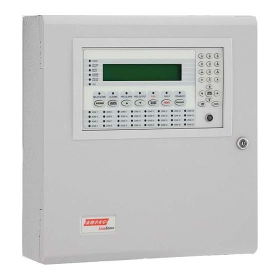
LOOPSENSE EN54 USER MANUAL Front Panel Control Card The Front Panel Control Card interfaces to the Main Control Board and supports; all the controls and functional indicators the FACP Reset Menu system control Serial or Parallel Printer port Figure 1: Front Panel Layout Levels of Access The FACP supports three levels of access. -
Page 7: Passwords
2. The panel responds by displaying a unique 10 digit key 3. Contact the local Ampac Service Centre and they will issue a temporary password 4. The temporary password is entered, and access is gained to the panel. The operator can... -
Page 8: System Controls & Indicators
LOOPSENSE EN54 USER MANUAL System Controls & Indicators The front panel has fourteen push button controls, a key switch and an alpha numeric keypad. Controls, Normal – Enabled (Key Switch) CONTROLS ENABLE KEY SWITCH. = OFF, = ON If the key switch is in the OFF position (access level 1), then the OVERRIDE, PREVIOUS, NEXT, SILENCE BUZZER and LAMP TEST controls are active. - Page 9 LOOPSENSE EN54 USER MANUAL Previous Momentary push button. Used to scroll the LCD display to view the previous available entry. Fire Output / Next Available at access level 1 and above FIRE OUTPUT Fire Output – Illuminated steady if a designated fire output has been activated and flashes if a FARE input is configured and active and remains so until the fire alarm condition is reset.
-
Page 10: Liquid Crystal Display
LOOPSENSE EN54 USER MANUAL DISABLED EVACUATE Disabled – The indicator is illuminated when one or more zone detectors, loop devices or panel outputs are disabled. Evacuate - Momentary push button. Turns on all alarm devices, illuminates the FIRE indicator, activates the output to the fire alarm routing equipment and announces the evacuate condition on the LCD. - Page 11 LOOPSENSE EN54 USER MANUAL PRINTER PARALLEL SERIAL LCD BACK LIGHT N1236 SYST BUZZER SILENCE STAT FAULT BUZZER FIRE TEST FRONT PANEL I/F RN10 CONFIG FAULT PRE-ALARM DELAY ACTIVE DISABLED FIRE FIRE OUTPUT ALARMS RN11 RN12 DIAGNOSTIC RESET SW28 ZONES 1 - 32 COMMS RN14 RN13...
-
Page 12: Displayed Conditional Responses
LOOPSENSE EN54 USER MANUAL Displayed Conditional Responses Normal Condition The POWER LED is illuminated meaning the mains voltage is present, and all other indicators are off. The 4 x 40 LCD will display the; DD/MM/YYYY HH:MM ACCESS LEVEL 1 current date, time and access level USER DESCRIPTOR LINE 1 on line 1 USER DESCRIPTOR LINE 2... -
Page 13: Fire Condition
LOOPSENSE EN54 USER MANUAL Fire Condition If an input or device is activated and it is configured to generate a fire condition the FACP responds to the fire as follows: Common FIRE LED will turn on steady Assigned zone fire LED will illuminate ... -
Page 14: Fault Condition
LOOPSENSE EN54 USER MANUAL Fault Condition When the system registers a fault condition: Common FAULT LED will be illuminated Corresponding front panel fault LED will illuminate Assigned zone fault LED will flash Panel buzzer will sound intermittently ... - Page 15 LOOPSENSE EN54 USER MANUAL Exception due to software failure in MTB – The system fault condition shall be hardware driven via software when panel reboots and can be silenced and cleared by pressing the STAR ‘*’ key on the FP provided the key-switch is in the access level 2 position.
-
Page 16: Pre-Alarm Condition
LOOPSENSE EN54 USER MANUAL Pre-Alarm Condition When a Pre-Alarm event occurs, the following actions take place. The associated LED will operate The condition will be reported on the LCD. The event will be logged and printed, where a printer is fitted. ... -
Page 17: Disabled Condition
LOOPSENSE EN54 USER MANUAL Disabled Condition When the user disables an input, output or zone the associated configured outputs will no longer operate and will no longer effect panel conditions. The system registers a disabled condition as follows: Common DISABLED LED will be illuminated ... -
Page 18: Test Functions
A fire event is recognised during the test, in which case the test will be aborted and the fire condition will be displayed. If the results do not match those described above, the operator is required to note it and report it to the Ampac Service Centre. Page 14... -
Page 19: Walk Test
LOOPSENSE EN54 USER MANUAL Walk Test Access level 2 Walk Test and Silent Walk Test is available via the Menu - Control - - Zone. - Select Zone - Silent Walk Test or - Walk Test The purpose of the walk test is to verify the detectors, MCP's and optionally the alarm devices (sounders) are functioning as required. -
Page 20: Device Locator
LOOPSENSE EN54 USER MANUAL Device Locator Access level 2 The Device Locator test is available via Menu - - Control - - Device - Select Device - Alarm led ON Device locator allows maintenance personnel to locate a particular device by forcing the device alarm LED ON. -
Page 21: Menu Structure
LOOPSENSE EN54 USER MANUAL Menu Structure Menu Layout and Navigation The main menu for the system is as shown below. The accessibility of this menu for the three access levels is as described previously and summarized below. Access Level 1: Menu not accessible Access Level 2: Menu partially accessible. -
Page 22: Generic Point Selection Screens
LOOPSENSE EN54 USER MANUAL 6.1.1 Generic Point Selection Screens Within the menu system there are several instances in which points are required to be selected in order to proceed further and display and/or manipulate the selected points. Points include Zones, Loops, Devices, Device Sub-Addresses, Panel Inputs, Panel Outputs and Add-Ons. -
Page 23: Add-On Point Selection
LOOPSENSE EN54 USER MANUAL Sub-Address Suffix: - Sub-Address Disabled 6.1.6 Add-On Point Selection Add-On module addresses 1 up to 30 can be selected, depending on type. SELECT ADD-ON: XX <add-on type> <selected add-on descriptor> ►A1 Add-On Address Prefixes: A – Add-On configured ... -
Page 24: Menu Structure & Navigation
LOOPSENSE EN54 USER MANUAL Menu Structure & Navigation The following should be read in conjunction with the complete “Menu Structure”. The primary components of the Menu Structure are; DISPLAY CONTROL EVENTS TOOLS SETUP PROGRAMMING The sections below have been broken down by primary component for ease of explanation Menu >... -
Page 25: Menu > Control
LOOPSENSE EN54 USER MANUAL Menu > Control Access Level 2 – to access this level the operator should use the “Controls Normal – Enable” keyswitch or enter the Password. NOTE: CONTROL 1: At Access Level 1, the entire menu is not accessible. 2: At Access Level 2, individual sounder disablement, DEVICE ZONE... -
Page 26: Menu > Control > Device
LOOPSENSE EN54 USER MANUAL ACTION:<action type> <dev type> AVALUE:XXX I:000 O:000 DRIFT:YYY%MODE:X ◄BACK:DISABLE 2:SUB ADDR 3:PRINT 4:ALARM LED ON Note: Option 2 shall be SUB ADDR (Sub-Address) or REM O/P (Remote Output) depending on the type of device being displayed. Input Screens: Pressing DEVICE ►... -
Page 27: Menu >Control > Panel
LOOPSENSE EN54 USER MANUAL Non-Sounder Output Screens: <output location> <status> <output descriptor> <assigned output type> <dev type> ◄BACK 1:DISABLE 2:ON 3:PRINT Sounder Output Screens: <output location> <status> <output descriptor> <assigned output type> <dev type> ◄BACK 1:DISABLE 2:ALERT 3:EVAC 4:PRINT 7.2.3 Menu >Control >... -
Page 28: Menu->Control->Panel->Output
LOOPSENSE EN54 USER MANUAL 7.2.3.2 Menu->Control->Panel->Output CONTROL PANEL OUTPUT MENU 1►SUPERVISED O/P 3|OPEN COLLECTOR O/P 2|RELAY O/P 4|AUXILIARY O/P 7.2.3.2.1 Menu->Control->Panel->Output->Supervised O/P Use the ▼▲ arrows to display the 4 available panel supervised outputs Non-Sounder Outputs: Zzzz Ppp SUP:Oo <status> <output descriptor>... -
Page 29: Menu->Control->Panel->Loop
LOOPSENSE EN54 USER MANUAL <add-on location> <status> <add-on descriptor> <add-on type> <add-on version> ◄BACK 1:DISABLE 2:I/O 3:PRINT Selecting “2:I/O” will display the individual inputs and/or outputs of the add-ons Use the ▼▲ arrows to display the available inputs and outputs Non-Sounder Outputs: <add-on location>... -
Page 30: Menu->Control->Panel->Delay Mode
LOOPSENSE EN54 USER MANUAL 7.2.3.7 Menu->Control->Panel->Delay Mode This menu is only accessible if investigation delays have been configured and the panel is in the day or night modes in which delays are configured. INVESTIGATION DELAY MODE: ON ◄BACK 1:OFF 7.2.4 Menu ->Control >... -
Page 31: Menu->Events->Goto
LOOPSENSE EN54 USER MANUAL 7.3.3 Menu->Events->Goto GOTO <event type> EVENTS 1►MOST RECENT 2|BY DATE 3|BY ENTRY Menu > Tools TOOLS DIRTY DEVICES LOOP STATISTICS LOW% MED% HIGH% RESET COUNT TOOLS MENU 1►DIRTY DEVICES 2|LOOP STATISTICS 7.4.1 Menu->Tools->Dirty Devices The compensation threshold level can be set to the default Low, Medium or High percentage. The selected default Low, Medium or High compensation threshold is displayed, and an asterisk shall appear next to the current selection where the medium threshold is the default. -
Page 32: Menu > Setup
LOOPSENSE EN54 USER MANUAL Menu > Setup SETUP DATE AND TIME DATE FORMAT DAYLIGHT SAVE ON/OFF TIME FORMAT DAY/NIGHT EARTH MON SUNDAY MONDAY TUESDAY WEDNESDAY THURSDAY FRIDAY SATURDAY SET ALL DISABLE PASSWORDS SETUP MENU 1►DATE AND TIME 3|EARTH MONITORING 2|DAY/NIGHT 4|PASSWORDS This menu is only accessible at access level 3. -
Page 33: Menu->Setup->Day/Night->Day
LOOPSENSE EN54 USER MANUAL 7.5.2.1 Menu->Setup->Day/Night->Day DAY/NIGHT SETTINGS - SUNDAY CURRENT - DAY: HH:MM NIGHT: HH:MM NEW - DAY: _ NIGHT: DEL▲ ◄BACK APPLY▼ NEXT► Back will return to day/night menu or previous day if not on first day selected. Next will proceed to the day/night settings for each of the remaining six days in sequence after which it will return to the day/night menu. -
Page 34: Menu > Programming
LOOPSENSE EN54 USER MANUAL Menu > Programming PROGRAMMING (*) ENTER PASSWORD ZONE DEVICE DELETE EDIT PANEL INPUT OUTPUT LOOP DESCRIPTOR SUPERVISED O/P RELAY O/P OPEN COLLECTOR O/P AUXILIARY O/P SOUNDERS GLOBAL ZONE ACTIVATION ACTIVATION LEARN OPTIONS AUTO LEARN EXTRA DEVICES MISMATCHED DEVICES MISSING DEVICES LEARN... -
Page 35: Menu->Programming->Device
LOOPSENSE EN54 USER MANUAL Use the alpha-numeric keys to key in descriptor characters. Pressing next (or enter) will update the programming. DAY MODE ZONE CONFIGURATION: INVESTIGATION CHANGE▼ ◄BACK NEXT► For day and night mode, choices are: NORMAL (No Timeout) ... -
Page 36: Menu->Programming->Device->Add
LOOPSENSE EN54 USER MANUAL SELECT DEVICE TYPE: <device type> CHANGE▼ ◄BACK NEXT► 7.6.2.1 Menu->Programming->Device->Add In this wizard the user can scroll through the desired device type to be added. The user is also prompted to save changes if required. 7.6.2.2 Menu->Programming->Device->Delete Zzzz Ppp Lll Dddd.s <device type>... -
Page 37: Menu->Programming->Device->Edit - Sub Input
LOOPSENSE EN54 USER MANUAL Press CHANGE▼ to browse through the available latching state options. Press NEXT► to go to the next field. EDIT PRE-DELAY: 0 (0-90 seconds) DEL ▲ #CLEAR ◄BACK NEXT► Key-in the new pre-delay value for the selected field. Press NEXT► to go to the next field. DAY SENSITIVITY: 100 (80-120%) DEL ▲... -
Page 38: Menu->Programming->Device->Edit - Sub Output
LOOPSENSE EN54 USER MANUAL TYPE: <device type> 1 DEVICE 2►SUB ADDRESS NEXT► If the device type has sub-address inputs or outputs this screen is displayed next: SELECT SUB ADDRESS: 1 <selected sub address descriptor> 2:I/P2 3:I/P3 4:O/P1 5:O/P2 1►I/P1 6:O/P3 Select 2 SUB ADDRESS and pressing NEXT►... - Page 39 LOOPSENSE EN54 USER MANUAL EDIT DEVICE TYPE: <device type> CHANGE▼ ◄BACK NEXT► Once the device is selected firstly the device type can be changed: WARNING: SETTINGS WILL BE DEFAULT EXCEPT ZONE NUMBER AND DESCRIPTOR PROCEED WITH CHANGE ◄BACK 1:YES If the device type is changed this confirmation screen is displayed: TYPE: <device type>...
-
Page 40: Menu->Programming->Panel
LOOPSENSE EN54 USER MANUAL NORMALLY ENERGISED: DISABLED CHANGE▼ ◄BACK NEXT ► Press CHANGE▼ to enable or disable the displayed zone action. Press NEXT► to go to the next zone action setting. RESPOND TO ALERT/EVAC: ENABLED CHANGE▼ ◄BACK NEXT► Press NEXT► to go to the next field. RESPOND TO CLASS CHANGE: ENABLED CHANGE▼... -
Page 41: Menu->Programming->Panel->Output
LOOPSENSE EN54 USER MANUAL EDIT ACTION TYPE: FIRE CHANGE▼ ◄BACK NEXT► Press NEXT► to go to the next field. INPUT TYPE: NON-LATCHING CHANGE▼ ◄BACK NEXT► Press NEXT► to go to the next field. EDIT CONTACT STATE: NORMALLY OPEN CHANGE▼ ◄BACK NEXT►... - Page 42 LOOPSENSE EN54 USER MANUAL ENTER ZONE NUMBER: 1_ DEL ▲ #CLEAR ◄BACK NEXT► Press NEXT► to go to the next field. FIXED ACTIVATION: NONE CHANGE▼ ◄BACK NEXT► Press NEXT► to go to the next field. OUTPUT TYPE: SOUNDER CHANGE▼ ◄BACK NEXT►...
-
Page 43: Menu->Programming->Panel->Loop
Press NEXT► to go to the next field. The user is then prompted to save any changes that may have been made. 7.6.3.4 Menu->Programming->Panel->Descriptor EDIT CUSTOM BANNER 1 AMPAC TECHNOLOGIES PTY. LTD._ DEL ▲ #CLEAR ◄BACK NEXT► The user may modify the two descriptors displayed on the normal screen... -
Page 44: Menu->Programming->Sounders->Zone Activation
LOOPSENSE EN54 USER MANUAL The activation mode choices are: EVACUATE ALERT ALERT TIMEOUT EVACUATE DELAYED GLOBAL <action type> ACTIVATION DELAY: 30 (0-999 Sec) #CLEAR ◄BACK NEXT► The activation mode screens are repeated for all action types in which the delays can be edited The user is then prompted to save any changes that may have been made. -
Page 45: Menu->Programming->Learn Options->Extra Devices
LOOPSENSE EN54 USER MANUAL AUTO LEARN CONFIGURATION WILL BE CHANGED ARE YOU SURE? ◄BACK 1:YES Select 1 to confirm. AUTO LEARN INITIALISING PLEASE WAIT ◄BACK NEXT► While the Auto Learn sequence is initialising all system functions cease, and the panel is prepared for Auto Learn. -
Page 46: Menu->Programming->Version
LOOPSENSE EN54 USER MANUAL Zzzz Ppp Ll Dddd.s <status> CONFIGURED TYPE: <device type> MISSING DEVICES XXX OF XXX ◄BACK 1:DELETE 2:DELETE ALL If no missing devices were detected the following screen is displayed for a short period before returning to the previous menu. NO MISSING DEVICES DETECTED 7.6.6 Menu->Programming->Version... -
Page 47: Event Logging
LOOPSENSE EN54 USER MANUAL Event Logging Events are logged into one of eight event type categories. Individual storage is pre-allocated for each event type amounting to a total of 1000 events: Event Type Maximum Capacity Fire Fault Disable Pre-Alarm Emergency Security User System... -
Page 48: Complete Menu Structure
LOOPSENSE EN54 INSTALLATION & COMMISSIONING Complete Menu Structure DISPLAY FIRE FAULT PRE-ALARM EMERGENCY SECURITY USER DISABLE TEST ABOUT CONTROL ZONE DEVICE NOTE: SUB ADDR AND REM O/P DEPEND DISABLE INPUTS DISABLE SOUNDERS SILENT WALK TEST WALK TEST DEVICE> INPUT ON THE SELECTED DEVICE DISABLE PRINT DISABLE... - Page 49 Dependencies on more than one alarm signal – Type C Fault signal from point Output to fault warning routing equipment Disablement of each addressable point Test condition UNCONTROLLED DOCUMENT NOTE: Due to AMPAC’s commitment to continuous improvement specifications may change without notice.
Need help?
Do you have a question about the LoopSense MAN 1572-4 and is the answer not in the manual?
Questions and answers