
Subscribe to Our Youtube Channel
Related Manuals for Ampac FireFinder Series II AS442


Summary of Contents for Ampac FireFinder Series II AS442
- Page 1 FIREFINDER SERIES II INSTALLATION, COMMISSIONING & OPERATION FireFinder Fire Alarm Control Panel Series II AS4428 Installation, Commissioning & Operation MAN 2986-1...
- Page 2 FIREFINDER SERIES II INSTALLATION, COMMISSIONING & OPERATION FIRE BRIGADE RESPONSE GUIDE 1. INDICATION (INCOMING FIRE ALARM CONDITION) ALARM ALARM LED FLASHING Loop X sensor X TYPE LCD DISPLAY of LX SX ZX STAT:ALARM DESCRIPTION TYPE, ADDRESS, DATE & TIME DATE & TIME ACKED ZONE ALARMS X OF XX and No of ACKNOWLEDGED ALARMS 2.
-
Page 3: Table Of Contents
FIREFINDER SERIES II INSTALLATION, COMMISSIONING & OPERATION TABLE OF CONTENTS Page No. About This Manual ........................1 Introduction ........................ 1 General Requirements ....................1 References......................... 1 Symbols ........................1 System Overview ........................2 FACP Configuration Examples ................... 3 FireFinder Description ......................4 Placing the Basic System into Operation ................ - Page 4 FIREFINDER SERIES II INSTALLATION, COMMISSIONING & OPERATION Setting the Function Time Facility ................30 Setting the Function Daynight Facility ............... 30 Function Logs Facility ....................30 The Function Test Facility..................31 Function Manual I/O Control ..................32 Function Access (Level II) / Passwords (Level III) ............. 32 8.7.1 Forgotten Passwords .................
- Page 5 FIREFINDER SERIES II INSTALLATION, COMMISSIONING & OPERATION 13.3 High Level Interface Expander (BRD43SPB) ............72 13.4 Expansion Board (302-688) ..................74 13.5 Expansion Controller (159-0077) ................74 SmartTerminal ........................75 14.1 SmartTerminal Controls and Indicators ..............75 14.2 LCD Screen Format ....................79 14.3 Operation .........................
-
Page 6: About This Manual
FIREFINDER SERIES II INSTALLATION, COMMISSIONING & OPERATION About This Manual Introduction This manual contains all the information required to install, commission and operate the FireFinder SERIES II Fire Alarm Control Panel (FACP) fitted with Version 6 software and is only available to and for the use of personnel engaged in its installation, commissioning and operation. -
Page 7: System Overview
FIREFINDER SERIES II INSTALLATION, COMMISSIONING & OPERATION System Overview The FireFinder Series II is an Intelligent Analogue / Addressable and / or Conventional Fire Alarm Control Panel capable of supporting: Apollo Discovery and XP95 Intelligent Detectors, Multisensor, Photoelectric, Ionisation, Thermal (heat) and CO detectors. -
Page 8: Facp Configuration Examples
FIREFINDER SERIES II INSTALLATION, COMMISSIONING & OPERATION FACP Configuration Examples 2 LOOP TERMINATION BOARD (302-7350) OR FRONT PANEL CONTROL (302-6906) 16Z CONVENTIONAL BOARD EARTH STUD (302-671B) CN17 MAINS MAIN CONTROL BOARD (BRD85MBA) CH16 CH15 SWITCH L2+ L1- +35V L2+ L1- +35V L2+ L1- +35V... -
Page 9: Firefinder Description
(max 32 Slave CPU’s) within the one cabinet may be fitted or external networking must be used. The FireFinder Series II has an internal ASPI (Ampac Serial Peripheral Interface) serial bus. This serial bus provides interfacing to the Brigade /PSU Monitor Board and if required up to eight (8) Sounder Board/s. - Page 10 FIREFINDER SERIES II INSTALLATION, COMMISSIONING & OPERATION BACKLIGHT MAIN BOARD RESET #2 UP TO 3 ADDITIONAL CN17 SLAVE CPU's (302-6692) RS485 COMMS TO CAN BE SLOTTED ONTO BACKPAN BORADS THE MAIN BOARD. CN11 LOOP COMMS EXTERNAL LOOP a b c COMMUNICATION O O O O O O...
-
Page 11: Placing The Basic System Into Operation
FIREFINDER SERIES II INSTALLATION, COMMISSIONING & OPERATION Placing the Basic System into Operation Unpacking Carefully unpack the FireFinder. The package should include: FireFinder SERIES II Fire Alarm Control Panel An Operators manual 003 keys Anti-Static Precautions To prevent damage to components, modules and boards, anti-static precautions MUST be observed while performing any task within the FACP. -
Page 12: Operational Parameters
FIREFINDER SERIES II INSTALLATION, COMMISSIONING & OPERATION Operational Parameters GENERAL Max No of Devices per Loop Max No of Devices per Conventional Zone Cable Loop Characteristics 2 core. 1.5 to 2.5mm² POWER SUPPLY Power Supply Output Voltage 27.4V Power Supply Output Current 2Amp, 5.6Amp or 18Amp 85 - 264VAC (47 –... -
Page 13: Power Supplies And Ac Mains Installation
FIREFINDER SERIES II INSTALLATION, COMMISSIONING & OPERATION LED Mimic (RS485) Single twisted shielded cable (No return loop) plus 2 core power or local supply. Maximum distance between each LED repeater card and FACP is 1.2km. Recommended Cable Type Hartland HC2335 Belden 9841 Radox FR Communication Fire Alarm Bell Connection... -
Page 14: Connecting The Mains Earth
FIREFINDER SERIES II INSTALLATION, COMMISSIONING & OPERATION 4.8.1 Connecting the Mains Earth All earth cabling shall be terminated to the panel Chassis Earth Terminal in a star configuration. The earth cable closest to the cabinet body shall have an M4 SPW beneath the lug then an M4 SPW and M4 nut. - Page 15 FIREFINDER SERIES II INSTALLATION, COMMISSIONING & OPERATION 5 AMP Power Supply Output Voltage: is set to 27.4 Volts. Mains cable should be no less than 0.75mm POWER SWITCH MAINS CORD BROWN (LOOKING AT REAR) (ACTIVE) BLUE (NEUTRAL) EARTH (GREEN) TO CHASSIS EARTH 27VDC TO BRIGADE TERMINAL PSU MONITOR BOARD...
-
Page 16: Current Limiter, Fuse Board (Brd85Clfb)
FIREFINDER SERIES II INSTALLATION, COMMISSIONING & OPERATION Current Limiter, Fuse Board (BRD85CLFB) The Current Limiter, Fuse Board provides protection for the boards, cards and other 27VDC distribution within the FACP when the 18Amp power supply is used. The four LED’s associated with the board indicate that 27VDC is available at each of the outputs CN1 –... -
Page 17: Brigade / Psu Monitor Board (Brd85Bpmb)
FIREFINDER SERIES II INSTALLATION, COMMISSIONING & OPERATION 4.10 Brigade / PSU Monitor Board (BRD85BPMB) The Brigade / PSU Monitor Board monitors and controls the power supply, battery charging, monitored / un-monitored inputs, outputs and the 7 relay outputs. Providing the Power supply has adequate capacity, monitored Bell/Sounder O/P’s are capable of driving 2 X 2Amp circuits. - Page 18 FIREFINDER SERIES II INSTALLATION, COMMISSIONING & OPERATION F3 2A Bell 2 To CN7 of the Main Controller Board Bell 1 F2 2A Monitored Required Ohms Bell Un-monitored or Sounder Auxiliary Monitored F4 1A Required Note: If a diode is NOT fitted internally to a bell / sounder a diode MUST be fitted as shown - fit 1N4004 or similar...
-
Page 19: Battery Connections (Tb1)
FIREFINDER SERIES II INSTALLATION, COMMISSIONING & OPERATION 4.10.1 Battery Connections (TB1) A FireFinder requires two (2) 12 volt batteries. The batteries should be placed into the bottom right hand side of the cabinet. A red and black lead coming from TB1 on the Brigade Board will be clearly seen in the same area, this lead is to be connected to the batteries red to positive and black to negative once the system is operating on Mains supply. -
Page 20: Warning System Connections (Tb5)
FIREFINDER SERIES II INSTALLATION, COMMISSIONING & OPERATION 4.10.4 Warning System connections (TB5) Warning systems such as the EV20 and EV40 are connected to the Brigade / PSU Monitor Board as shown below. Note: EOL not required in connection as it is fitted at the EV20/EV40 module Note: TB4 &... -
Page 21: Main Board (Brd85Mba)
FIREFINDER SERIES II INSTALLATION, COMMISSIONING & OPERATION 4.11 Main Board (BRD85MBA) The Main Board is the "heart" of the FACP and carries the devices for interconnecting to all the other Boards, a buzzer for auditory indication, the backlight power supply for the LCD and CPU Reset. The Main CPU is mounted on this board and connected to it by CN11. -
Page 22: Front Panel Board (302-690)
FIREFINDER SERIES II INSTALLATION, COMMISSIONING & OPERATION 4.12 Front Panel Board (302-690) The Front Panel Board provides the buttons used to control the FACP as well as all LED indications. All LED’s are surface mounted and the buttons are embedded within the board. The LCD is viewed / protected by a clear Perspex screen. -
Page 23: Main Cpu (Brd85Cpu)
FIREFINDER SERIES II INSTALLATION, COMMISSIONING & OPERATION 4.13 Main CPU (BRD85CPU) The Main CPU holds the main central processing unit for the FACP. BRD85CPU is a 4-layer surface mount board The processor (U1) is a Motorola MC68302, running at 20MHz. ... -
Page 24: Slave Cpu (302-669)
FIREFINDER SERIES II INSTALLATION, COMMISSIONING & OPERATION 4.14 Slave CPU (302-669) The Slave CPU (Central Processing Unit) provides the interfacing signals and I/O’s required to allow the FACP to connect / communicate to a variety of termination boards. A single chip micro controller U1 controls all operations of the FACP Slave CPU. This device contains the control program within Read Only Memory (ROM). -
Page 25: Conventional Zone Board (302-671)
FIREFINDER SERIES II INSTALLATION, COMMISSIONING & OPERATION 4.15 Conventional Zone Board (302-671) Under the control of a Slave CPU the Conventional Zone Board provides the interface between it and the external conventional devices. 16 Conventional zones can be connected to TB4 to TB1, with a limit of 32 conventional detectors can be connected to TB4 to TB1. -
Page 26: Addressable Loop Termination Board (302-735)
Connect the XP-95 / DISCOVERY loop to the panel as shown below. AMPAC strongly recommend that the LoopManager test set is used to check that the Apollo loop has been correctly installed and commissioned before connecting it to the FireFinder™. -
Page 27: Addressable Loop Termination Board (Brd86Dltb-B)
Connect the XP-95 / DISCOVERY loop to the panel as shown below. AMPAC strongly recommend that the LoopManager test set is used to check that the Apollo loop has been correctly installed and commissioned before connecting it to the FireFinder™. -
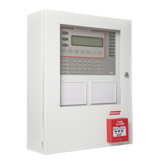
Page 28: Firefinder Control Panel
FIREFINDER SERIES II INSTALLATION, COMMISSIONING & OPERATION FireFinder Control Panel Figure 27: The FireFinder™ Control Panel with a 4 Line LCD FIRFIGHTER FACILITY ALARM (Red): This LED will flash if any unacknowledged alarms are present on the system. If all alarms have acknowledged it will light steady. FAULT (Yellow): This LED will light steady if there are any faults on the system, whether they are loop faults, module faults, device faults etc. - Page 29 FIREFINDER SERIES II INSTALLATION, COMMISSIONING & OPERATION ACKNOWLEDGE Pressing this key will acknowledge an alarm currently displayed on the LCD. It will also silence the panel buzzer, which sounds whenever there is an alarm (optional) or fault. RESET Pressing this key will reset the panel, clearing any acknowledged alarms and taking the LCD display back to its default screen, unless there are any un-cleared faults or isolated devices, these will continue to be displayed.
- Page 30 FUNCTION key will display the function menu on the LCD. FIREFINDER 15/7/2005 14:00:00 AMPAC PH: 08 9242 3333 SYSTEM IS NORMAL LCD DISPLAY - This screen can be configured with the servicing companies’ name and phone number. It also displays the current date, time and that the system is normal (no faults and alarms).
-
Page 31: Functions And Menus
In its normal state the FireFinder™ will display a screen similar to that shown below. FIREFINDER 15/7/2005 14:00:00 AMPAC PH: 08 9242 3333 SYSTEM IS NORMAL Figure 28: The Default LCD Display This screen can be configured with the servicing company’s name and phone number via a laptop or modem. -
Page 32: The Main Menu
FIREFINDER SERIES II INSTALLATION, COMMISSIONING & OPERATION The Main Menu The MAIN MENU is accessed by pressing MENU. MAIN MENU 0: ALARMS 1:PREALARMS 2: FAULTS 3:ISOLATES 4: STATUS 5:TEST MENU FUNCTION SELECT NO. Figure 29: The Main Menu Numbering System: denotes the menu structure number and denotes the sub-menu... - Page 33 FIREFINDER SERIES II INSTALLATION, COMMISSIONING & OPERATION Once the above is selected follow the prompts and enter the; I/O controller number then the input or output on that controller or, loop, sensor and output number on that device. The LCD will display if it is configured and if so a description of what that input or output does and its current state.
-
Page 34: Testing Menu
FIREFINDER SERIES II INSTALLATION, COMMISSIONING & OPERATION Loop 1 Sensor 1 SMOKE L1 S1 Z2 STAT: NORMAL AVALUE: 25 MODE: 0 1: 000 O: 000 Figure 35: Analogue Values Testing Menu Is pressed to access the ALARM, FAULT AND LAMP TESTING MENU. TESTING MENU 0: ALARM 1: FAULT... -
Page 35: Main Functions
FIREFINDER SERIES II INSTALLATION, COMMISSIONING & OPERATION Main Functions LEVEL III MAIN FUNCTIONS LEVEL II MAIN FUNCTIONS 0: DATE 1: TIME 2: DAYNIGHT SETTINGS 3: LOGS 0: DATE 1: TIME 2: DAYNIGHT SETTINGS 3: LOGS 4: TESTS 5: I/O 6: PASSWORDS 4: TESTS 5: I/O 6: ACCESS SELECT NO: SELECT NO:... -
Page 36: The Function Test Facility
FIREFINDER SERIES II INSTALLATION, COMMISSIONING & OPERATION The type of log, number and totals logged, date and time of the ALARM, FAULT, ISOLATE, SYSTEM or I/O as well as device information will be displayed. The SYSTEM screen displays events and watchdog activity. From these screens the operator can select two other facilities, they are;... -
Page 37: Function Manual I/O Control
FIREFINDER SERIES II INSTALLATION, COMMISSIONING & OPERATION Function Manual I/O Control Press To display the Manual I/O Control menu MANUAL I/O CONTROL 0: INPUT 1: OUTPUT 2: REMOVE MANUAL CONTROL SELECT NO. Figure 41: The Manual I/O Control Menu Manual I/O control allows the technician to turn ON or Off inputs and outputs off a device to facilitate testing or isolation of plant during maintenance. -
Page 38: Forgotten Passwords
Take note of the 4 digit password number displayed on the screen; then Contact the AMPAC head office and quote the above number; A temporary password will be issued and a new password can then be programmed into the FACP. -
Page 39: Function Programming
FIREFINDER SERIES II INSTALLATION, COMMISSIONING & OPERATION Function Programming Press To display the Level III Programming Menu. ON SITE PROGRAMMING MENU 0: CONV ZONE 1: DEVICE 2: INPUT 3: OUTPUT 4: PANEL BASED MCP 5: SUB ADDRESS 6: WDOG SELECT NO. -
Page 40: Device Programming
FIREFINDER SERIES II INSTALLATION, COMMISSIONING & OPERATION After scrolling through the groups and entering what I/O GROUPS will be turned on by what module/s or device/s in a zone/s the operator is prompted to press ENTER to confirm the entries and / or changes. 8.8.2 Device Programming Press ... -
Page 41: Manual Call Point (Mcp)
FIREFINDER SERIES II INSTALLATION, COMMISSIONING & OPERATION 8.8.5 Manual Call Point (MCP) Press MCP: The operator will be prompted to enter the NODE Number, that is the Node or panel on which the MCP is mounted. 8.8.6 Sub Address Press ... -
Page 42: Mismatch Detected
FIREFINDER SERIES II INSTALLATION, COMMISSIONING & OPERATION Select (Selecting presents the PROGRAMMING MENU) then (as seen below) then ENTER to ADD the module or device to the configuration, or skip to resolve the changes manually in the Programming Menu. 0: ADD EXTRA MODULES 1: ADD EXTRA DEVICES 2: DEVICE TYPE MISMATCH 3: MODE MISMATCH... -
Page 43: Incoming Fire Alarm Signal
FIREFINDER SERIES II INSTALLATION, COMMISSIONING & OPERATION Incoming Fire Alarm Signal Will operate the red common LED fire indicator Will display location of fire alarm origin on the LCD Will activate external alarm. Will activate the internal FACP buzzer. ... -
Page 44: Accessing A Loop, Sensor Or Zone
FIREFINDER SERIES II INSTALLATION, COMMISSIONING & OPERATION Accessing a Loop, Sensor or Zone LOOP OR SENSOR From the default display, press LOOP Enter the loop number you wish to interrogate then press SENSOR. Press the button for the sensor number. ... -
Page 45: Expanding The Facp With Compatible Firefinder Boards
FIREFINDER SERIES II INSTALLATION, COMMISSIONING & OPERATION Expanding the FACP with Compatible FireFinder Boards 11.1 Ancillary Services The FACP has been designed such that detectors and/or call points, in addition to giving an alarm and calling the fire brigade, will close or open circuits of ancillary services by means of relays or similar devices. -
Page 46: Compatible Firefinder Boards
FIREFINDER SERIES II INSTALLATION, COMMISSIONING & OPERATION 11.2 Compatible FireFinder Boards Module / Board Part No Fast Fit Kit Item No Max No Slave CPU 302-669 159-0007 8 per Controller # 1 Conventional Zone Board 302-671 159-0005 8 per Controller Apollo Loop Termination Board 302-735 159-0003... -
Page 47: 16/16 Input / Output Board (302-672)
FIREFINDER SERIES II INSTALLATION, COMMISSIONING & OPERATION 11.3 16/16 Input / Output Board (302-672) The Input / Output Board is connected to the slave CPU via CN1 and acts as the interface between the Slave CPU, 8 Way Relay Board and the 16 Way Opto Input Board. Dependant on the panel configuration a maximum of 8 Input / Output boards can be daisy chained together. -
Page 48: Way Input Board (302-677)
FIREFINDER SERIES II INSTALLATION, COMMISSIONING & OPERATION 11.5 16 Way Input Board (302-677) Opto-Inputs: Up to 16 inputs can be connected to the 16 Way Input Board. These inputs are required to be voltage free contacts as shown below. AS AN EXAMPLE INPUTS 1 AND 16 CONNECTED TO VOLTAGE-FREE CONTACTS COMCOM... -
Page 49: Fire Fan Module (Brd25Fcb)
FIREFINDER SERIES II INSTALLATION, COMMISSIONING & OPERATION 11.7 Fire Fan Module (BRD25FCB) The Fire Fan Module has four (4) separate fan controls each having an On, Auto and Off function switch and a set of three (3) monitoring LED’s. The LED’s indicate the status of the equipment e.g. Run, Fault or Stop. -
Page 50: Zone & General Indicator Card (Brd85Gibb)
FIREFINDER SERIES II INSTALLATION, COMMISSIONING & OPERATION 11.9 Zone & General Indicator Card (BRD85GIBB) The General Indicator Card (BRD85GIBB) comes in two versions each consisting of a front clip on surround, decal, mounting frame, PCB and is clipped into the front panel of the FACP to provide visual LED indication of;... -
Page 51: Switch And Indicator Card (Brd25Gib - B)
FIREFINDER SERIES II INSTALLATION, COMMISSIONING & OPERATION 11.10 Switch and Indicator Card (BRD25GIB – B) This Card can effectively perform 2 different functions. Firstly the indicators monitor the first 8 inputs of the 16 Way Input Termination Board while secondly the switches can be programmed to manually operate a specific relay in the system. -
Page 52: Way Sounder Monitor Board (302-7420/1)
FIREFINDER SERIES II INSTALLATION, COMMISSIONING & OPERATION 11.11 8 Way Sounder Monitor Board (302-7420/1) The 8 way Sounder Monitor Board allow a larger number of bells and sounders to be connected to the System. The 302-742 is built in two versions: 1. -
Page 53: Printer
FIREFINDER SERIES II INSTALLATION, COMMISSIONING & OPERATION 11.12 Printer Specifications Printing method: directed impact dot matrix Interface: 8 bit parallel interface Printing mechanism: 4/6 pin shuttle Interface port: 26 PIN flat plug 11.12.1 Indicators and Buttons The front panel has an LED indicator and two buttons SEL (SELECT), LF (LINE FEED). -
Page 54: Maintenance
FIREFINDER SERIES II INSTALLATION, COMMISSIONING & OPERATION Self-Test Mode With power applied (green LED illuminated) push the SEL button. This will turn off the LED. Press and hold in the LF button, then press the SEL button again and the printer will enter the Self Test mode. - Page 55 FIREFINDER SERIES II INSTALLATION, COMMISSIONING & OPERATION Mechanism Release Hinges Button PUSH Push Buttons Paper Note: Ink Ribbon Front Door Removed Cassette Note: Replacement Paper Roll Front Door Removed Figure 70: Head Mechanism Rotation and Paper Roll Removal / Insertion Take out the empty paper roll and roller Put the new paper roll onto the paper roller and replace as shown above.
-
Page 56: Printer Connections And Jumpering
FIREFINDER SERIES II INSTALLATION, COMMISSIONING & OPERATION 11.12.3 Printer Connections and Jumpering Mounted on the back of the printer mechanism is the PCB that carries the; Connectors for interconnection to the Main Board, Jumper links required to set the programmed print modes; and ... -
Page 57: Agent Release Control
FIREFINDER SERIES II INSTALLATION, COMMISSIONING & OPERATION 11.13 Agent Release Control Agent Release control consists of a Agent Release Module, Termination Board and an optional Local Control Station. Operation Introduction The Agent Release Module and Termination Board communicate with the FACP via the RS485 multi-drop bus. - Page 58 FIREFINDER SERIES II INSTALLATION, COMMISSIONING & OPERATION Stage 1 outputs are switched to +24VDC. (FIRE ALARM sign illuminated, aural alarm sounds). Stage 2 outputs are switched to +24VDC. (FIRE ALARM, EVACUATE & DO NOT ENTER signs illuminated, aural alarm sounds). ...
- Page 59 FIREFINDER SERIES II INSTALLATION, COMMISSIONING & OPERATION A Zone Fault. A Fault on the interlock input. A Fault with a LCS. Note #1: The common fault indicator on the Agent Release Module and Local Control Station is illuminated for any Fault condition.
-
Page 60: Agent Release Module (Brd25Arb-A)
FIREFINDER SERIES II INSTALLATION, COMMISSIONING & OPERATION 11.13.1 Agent Release Module (BRD25ARB-A) The Agent Release Module controls and monitors all the requirements for agent release and carries the slide in label for identification of the agent and application area. Manual Release Quiescent Switch Current:... -
Page 61: Local Control Station (Brd25Arb-B)
FIREFINDER SERIES II INSTALLATION, COMMISSIONING & OPERATION 11.13.2 Local Control Station (BRD25ARB-B) The Local Control Station (LCS) is supplied fitted into an IP40 rated enclosure and has the same indicators and Manual Release switch as the Agent Release Module within the Fire Alarm Control Panel (FACP) but no Agent Select button or Service Inhibit keyswitch. - Page 62 FIREFINDER SERIES II INSTALLATION, COMMISSIONING & OPERATION Lifting the cover and pressing the MCP starts the manual agent release sequence. This two action safety feature prevents any accidental operation of the control and should not be disabled. Agent Release / LCS Indicators There are 12 indicators on both the Agent Release Module and Local Control Station.
- Page 63 FIREFINDER SERIES II INSTALLATION, COMMISSIONING & OPERATION INITIAL AGENT (Yellow) Illuminated when the “Initial“Agent is selected. RESERVE AGENT (Yellow) Illuminated when the “Reserve “Agent is selected. Local Control Panel Inhibit TO INHIBIT AUTOMATIC AGENT RELEASE LIFT COVER AND PRESS BUTTON The agent inhibit switch has an internal lamp fitted with yellow lens.
-
Page 64: Agent Release Termination Board (Brd25Atb)
FIREFINDER SERIES II INSTALLATION, COMMISSIONING & OPERATION 11.13.3 Agent Release Termination Board (BRD25ATB) + - Outputs are Monitored Monitored SYST. STAGE2 STAGE1 RELEASE LCS CABLE INPUTS FIRED INOP. SIG+ + L.PSW- 0VDC MAIN RESV N/0 COM + N/0 COM SCRN SIG- +24VDC + PSW -... -
Page 65: Interface Wiring
FIREFINDER SERIES II INSTALLATION, COMMISSIONING & OPERATION 11.13.4 Interface Wiring Monitored Inputs TB2 1 & 2 Solenoid & Metron This input relies on N/O or N/C relay contacts used in conjunction with 22K EOL and 4K7 series resistors. The type of agent release mechanism and contacts used has to be set in the Programming Menu for the input to function as per the manufacturers specifications and be in accordance with the relevant Standard. -
Page 66: Warning Signs
FIREFINDER SERIES II INSTALLATION, COMMISSIONING & OPERATION 11.14 Warning Signs Description The warning signs are driven by a 2 wire system and may be configured for single or dual stage operation. An on-board buzzer provides an audible warning which may be disabled by removing JP3. External evacuation devices, e.g. - Page 67 FIREFINDER SERIES II INSTALLATION, COMMISSIONING & OPERATION Configuration – Jumper Settings JP 1 (Continuous / Flashing) JP 2 (Single / Dual Stage) LED's Permanently Full sign on for Stage 1-2 Continuous 1-2 Single Stage 1&2 2-3 Flashing LED's flashing at 2-3 Dual Stage Half sign on for Stage 1 (DEFAULT)
-
Page 68: Occupant Warning Systems
FIREFINDER SERIES II INSTALLATION, COMMISSIONING & OPERATION 11.15 Occupant Warning Systems The EV20, EV40, EV60 and EV120 are compact single zone occupant warning devices that when triggered produce Alert and Evacuation signals to meet the requirements of AS1670.1. EV20 At the heart of an EV20 single zone occupant warning system is a microprocessor that generates the alert and evacuation signals, controls timing and the input / output. - Page 69 FIREFINDER SERIES II INSTALLATION, COMMISSIONING & OPERATION Control Module When the control switch is in; AUTOMATIC - occupant warning signals and if applicable verbal messaging is under the control of the microprocessor and outputted to the speaker system when it receives a “warning system” signal from the FACP.
- Page 70 ( FACTORY SETTING "0" ) AND I/P SET TO 1 2 3 4 NON-LATCHING 5 WAY CABLE - MESSAGE SW1 TIME CONTROL 260-0027 OUT TABLE AMPAC S T D MSG3 EVACMESSAGE SW 1 OPTIONAL VERBAL LATCHING 0 ( EVAC ONLY ) MESSAGE BOARD...
- Page 71 FIREFINDER SERIES II INSTALLATION, COMMISSIONING & OPERATION EV40 Cabling NOTE 1: "WARNING SYSTEM" IS A MONITORED FACP O/P. THE EOL 8 OHM IS ONBOARD THE EV40 AND IS EFFECTIVELY MADE TO BE O/C SPARE o o o o o (AT TB1) DURING AN EV40 FAULT CONDITION. THIS PRODUCES JUMPERS o o o o o EVACTRON...
-
Page 72: Ev60 / 120
FIREFINDER SERIES II INSTALLATION, COMMISSIONING & OPERATION 11.16 EV60 / 120 The EV60 & 120 are essentially an EV20 MPU and driver but with 60 and 120 watt output amplifiers powered from a Current Limit Fuse Board. Figure 89: EV60 EV120 11.17 EV3000 HLIE Interface Operation... -
Page 73: Brigade Devices
FIREFINDER SERIES II INSTALLATION, COMMISSIONING & OPERATION Brigade Devices 12.1 ASE (Vic Metro) Brigade Box The ASE Brigade Box interfaces the Victorian Fire Brigade into the FireFinder SP series of FACP’s. NOTE: THE BATT FAIL RELAY TB10 FAULT ISOL ON THE BRIGADE BOARD ALARM BATT FAIL IS NORMALLY ENERGISED... -
Page 74: Expanding The System Through Networking
FIREFINDER SERIES II INSTALLATION, COMMISSIONING & OPERATION Expanding the System through Networking Expanding the system can be achieved in various ways and requires the use of boards specifically designed for communications purposes and boards that actually expand the system. 13.1 Communications: Network Interface Card (BRD85NIC) The Network Interface Board provides the RS485 communication buses via CN18 on the Main Controller (Loop Comms) to allow the networking of multiple panels in different combinations, e.g. - Page 75 FIREFINDER SERIES II INSTALLATION, COMMISSIONING & OPERATION PANEL 1 CN17 MAIN CONTROL BOARD (BRD85MBA) CH16 CH15 CN20 CN13 CN14 CN15 CN11 CN18 RN20 RN17 CN10 PSU MONITOR CN16 BRIGADE I/F 16 Way MODEM 16 Way EXPANSION PANEL EXPANSION LEDS FRONT PANEL PRINTER CN17 MAIN CONTROL BOARD (BRD85MBA)
-
Page 76: Communications Extender Board (Brd82Ltb)
FIREFINDER SERIES II INSTALLATION, COMMISSIONING & OPERATION 13.2 Communications Extender Board (BRD82LTB) The Communications Extender Board is mounted inside the FACP and provides protected RS485 communications and 27VDC to the SmartTerminal Termination Board/s and LCD/s and LED Mimics. CH16 +24VDC C O M CN20 TO NEXT SmartTerminal... -
Page 77: High Level Interface Expander (Brd43Spb)
FIREFINDER SERIES II INSTALLATION, COMMISSIONING & OPERATION 13.3 High Level Interface Expander (BRD43SPB) Hardware The High Level Interface Expander consists of a serial port under the control of a microcontroller. Communications between the FACP and this board is via the RS485 control bus with each board having a dedicated link and selectable 4 bit address. - Page 78 FIREFINDER SERIES II INSTALLATION, COMMISSIONING & OPERATION RS 232 RS 485 CN17 MAIN CONTROL BOARD (BRD85MBA) CH16 CH15 CN20 RJ45 CN13 CN14 CN15 CN11 CN18 RS485 HLI CONTROLLER SmartGraphics (BRD43SPB) FACP MODBUS RN20 RN17 FACP 0V ADDRESS ZDN2 1 2 3 4 RS 232 RJ45 RS 485...
-
Page 79: Expansion Board (302-688)
FIREFINDER SERIES II INSTALLATION, COMMISSIONING & OPERATION 13.4 Expansion Board (302-688) The Expansion Connection Board is used to increase the capacity of the controller from 4 Slave CPU’s to 8. Connection from the Controller to the Expansion Board, which must be mounted within 200mm of the Controller, is made via a 20 way flat cable Slave CPU number 5 is an integral part of the Expansion Board, only Slave CPU’s 6, 7 and 8 are plug ins. -
Page 80: Smartterminal
FIREFINDER SERIES II INSTALLATION, COMMISSIONING & OPERATION SmartTerminal SmartTerminal connects to the FireFinder Fire Alarm Control Panel (FACP) via the RS485 multidrop communication port. Generally it is designed to be used anywhere where the status of the FACP is required to be monitored by local personnel and limited control is required. ... - Page 81 FIREFINDER SERIES II INSTALLATION, COMMISSIONING & OPERATION Controls & Indicators EXTERNAL BELL ISOLATE (Yellow) Illuminated when the External Bell output has been isolated either at the SmartTerminal or the FACP. External Bell Isolate Press to isolate the External Bell output (associated LED illuminated). Press again to re-enable the output (associated LED extinguished).
- Page 82 FIREFINDER SERIES II INSTALLATION, COMMISSIONING & OPERATION ALARM (Red) General fire alarm indicator. The LED will flash until all alarms have been acknowledged. Once Acknowledged the LED will remain steady until all alarms have been cleared by Reset. Acknowledge Acknowledges the alarm condition of the sensor or conventional zone that is currently displayed on the LCD.
- Page 83 FIREFINDER SERIES II INSTALLATION, COMMISSIONING & OPERATION Key Switch Controls enable key switch. = OFF, = ON Access level 1 (OFF) By Default. Only the Acknowledge, previous and next front panel controls are operative. All other controls operate in access level two. Access level 2 (ON) is entered when the key-switch is in the ENABLED position.
-
Page 84: Lcd Screen Format
FIREFINDER SERIES II INSTALLATION, COMMISSIONING & OPERATION 14.2 LCD Screen Format There are 3 events that can be reported and displayed by SmartTerminal. The types of event are; Alarm Faults and Isolates. The types of events are only associated with sensors and detectors hence faults associated with modules, loops O/C –... - Page 85 FIREFINDER SERIES II INSTALLATION, COMMISSIONING & OPERATION Normal / Default: The format for reporting that everything is normal is: Current Date and Time (DD/MM/YYYY HH:MM) System Status This screen is only displayed when there are no alarms, fault or disables on the panel. The default screen is only displayed when there are no device alarms, device faults or device disables present on the system.
-
Page 86: Operation
FIREFINDER SERIES II INSTALLATION, COMMISSIONING & OPERATION 14.3 Operation The operation of SmartTerminal can be considered to be in one of three states, these are; 1. Power up - when the SmartTerminal is initialising 2. Normal - when the SmartTerminal address has been set and is communicating with the FACP, reporting normal / abnormal conditions and controlling the FACP via the front panel controls 3. -
Page 87: Setting The Address
FIREFINDER SERIES II INSTALLATION, COMMISSIONING & OPERATION 14.4 Setting the Address Open the front door; locate the “CONFIG” button situated on the left hand side of the PCB and press for 3 seconds. The buzzer and “Config” LED will double beep and flash respectively to indicate that the Configuration mode has been entered. -
Page 88: Mechanical
FIREFINDER SERIES II INSTALLATION, COMMISSIONING & OPERATION 14.5 Mechanical SmartTerminal essentially consists of two PCBs; 1. BRD82LTB – FACP –. The LCDA Termination Board is mounted inside the FACP and provides the protected RS485 communications and 27VDC to the SmartTerminal. 2. -
Page 89: Installation & Cabling
FIREFINDER SERIES II INSTALLATION, COMMISSIONING & OPERATION 14.6 Installation & Cabling The Communications Extender Board (Item Number 159-0129) should be mounted into the FACP and cabled as shown below. It should be noted the Communications Extender Board and its supporting plate is mounted in a piggy back fashion onto one of the loop / zone boards. -
Page 90: Specifications
FIREFINDER SERIES II INSTALLATION, COMMISSIONING & OPERATION 14.7 Specifications MECHANICAL Dimensions ABS Cabinet: ( mm ) 195mm (H) x 345mm (W) x 50mm (D) ENVIROMENTAL Temperature: -5ºC to + 55ºC Humidity: 25% to 75% INPUT POWER Operating Voltage ( nominal ): 27VDC Operating Voltage ( minimum ): 18VDC... -
Page 91: Setting The Smartterminal Controller Configuration In Configmanager
FIREFINDER SERIES II INSTALLATION, COMMISSIONING & OPERATION 14.8 Setting the SmartTerminal Controller Configuration in ConfigManager Right click on the Controller icon and select “Edit Module Types” to bring up the following screen/s. Figure 107: The Controller Edit / Add Module Types Screens Click within the check box to “tick”... -
Page 92: Trouble Shooting Chart
FIREFINDER SERIES II INSTALLATION, COMMISSIONING & OPERATION In the above example Card 1 & 2; Are active Are situated in the factory floor area 8 Will display all Alarms Will not display any Faults, and Will not display any Disables Card 3 ... -
Page 93: Rs232 Modem / Programming / Debug Interfacing
Rx Data DB9F CONNECTOR DB9F CONNECTOR ( Female Rear View ) ( Female Rear View ) To Modem or PC Plugs into FACP Figure 110: Modem / Programming / Debug Cabling Note: Debug/Notebook cables are available from AMPAC Page 88... -
Page 94: List Of Compatible Detectors
Sounder Control Unit 55000-823 Apollo XP95 Intrinsically Safe Protocol Translator 55000-855 Zone Monitor 55000-813 Loop Sounder 55000-261 Consult your local Ampac 3-IOD 3 Input / 3 Output Device Ampac SID Single Input Device Ampac Ampac Zone Interface Device Distributor Page 89... -
Page 95: Certification Information
FIREFINDER SERIES II INSTALLATION, COMMISSIONING & OPERATION Certification Information The FireFinder™ is designed and manufactured by: AMPAC TECHNOLOGIES PTY LTD 7 Ledgar Rd Balcatta WA 6021 Western Australia HEAD OFFICE 61-8-9242 3333 FAX: 61-8-9242 3334 Manufactured to: Certificate of Compliance Number:... -
Page 96: Troubleshooting Chart
Can not access Function menu Incorrect Password entered Ring AMPAC and directions will be given to Forgotten password provide you with a temporary code An Analogue Fault occurs when using a A 1.8k Ohm resistor must be placed in series with... -
Page 97: Address Setting
FIREFINDER SERIES II INSTALLATION, COMMISSIONING & OPERATION Address Setting BINARY ADDRESS SETTING (APOLLO) SERIES XP95 - ADDRESS DATA DIL SWITCH: ON = 1 OFF = 0 ADDRESS TAG FOR DETECTORS (I/O DEVICES) DIL switch setting DIL switch setting DIL switch setting DIL switch setting DIL switch setting Addr 1234567 Addr... -
Page 98: Glossary Of Terms
FIREFINDER SERIES II INSTALLATION, COMMISSIONING & OPERATION Glossary of Terms ACF: ANCILLARY CONTROL FACILITY ACKD: ACKNOWLEDGED AHU: AIR HANDLING UNIT ALM: ALARM AVF: ALARM VERIFICATION FACILITY AZF: ALARM ZONE FACILITY AZC: ALARM ZONE CIRCUIT RELAY COMMON CONTACT (WIPER) CIC: CONTROLLER INTERFACE CARD CONNECTOR CPU: COMMON PROCESSOR UNIT... -
Page 99: Definitions
FIREFINDER SERIES II INSTALLATION, COMMISSIONING & OPERATION Definitions Addressable system - a fire alarm and detection system that contains addressable alarm zone facilities or addressable control devices. Alarm Verification Facility (AVF) - that part of the FACP, which provides an automatic resetting function for spurious alarm signals so that they will not inadvertently initiate Master Alarm Facility (MAF), or ACF functions. -
Page 100: Quick Reference Guides
FIREFINDER SERIES II INSTALLATION, COMMISSIONING & OPERATION Quick Reference Guides MENU KEY / FUNCTION KEY MAIN MENU OPTIONS MENU FUNCTION ( TO ENTER MENU / TO FUNCTION MENU ) ALARMS ( DISPLAY ALARMS ) SPACE PREALARMS ( DISPLAY PRE-ALARMS ) FAULTS ( DISPLAY FAULTS OF SELECTED FIELDS ) ZONES/SENSORS SPACE... - Page 101 FIREFINDER SERIES II INSTALLATION, COMMISSIONING & OPERATION FUNCTION MENU OPTIONS Quick Reference FireFinder FUNCTION KEY ( TO ENTER FUNCTION FIELD ( ENTER PASSWORD ) ) MENU FUNCTION FUNCTION KEY ( TO ENTER FUNCTION FIELD ( ENTER PASSWORD ) ) DATE ( DD/MM/YYYY ) MENU MENU FUNCTION KEY ( TO ENTER FUNCTION FIELD ( ENTER PASSWORD ) )
-
Page 102: Statement Of Compliance
FIREFINDER SERIES II INSTALLATION, COMMISSIONING & OPERATION Statement of Compliance Please PRINT 1. Name of building 2. Address Fire Alarm Control Panel Brand Name 3. I/WE have installed in the above building an alteration to the system manufactured by, a system manufactured by Name of Service Provider 4. - Page 103 FIREFINDER SERIES II INSTALLATION, COMMISSIONING & OPERATION 15. I/We Print Name/s Hereby certify that the installation has been thoroughly tested from each actuating device and that a test of the transmission of the alarm signal to the monitoring service provider has been satisfactorily carried out.
-
Page 104: Installation Details
FIREFINDER SERIES II INSTALLATION, COMMISSIONING & OPERATION 23.1 Installation Details # Indicate with a number in brackets the number of actuating devices in concealed spaces. * Add addressable loop number in brackets where applicable. Zone Number and Type of Actuating Devices Thermal Fire Flame... -
Page 105: Commissioning Test Report
FIREFINDER SERIES II INSTALLATION, COMMISSIONING & OPERATION Commissioning Test Report This FireFinder Fire Alarm Control Panel is installed at: Company Name Street Suburb State / Country Post Code (Company Name & Installation Address ) Owner or Owners' Authorized Representative: Company Name Street Suburb... -
Page 106: Procedure
FIREFINDER SERIES II INSTALLATION, COMMISSIONING & OPERATION 24.1 Procedure The following tests are the minimum that shall be performed when commissioning a system using the FireFinder Fire Alarm Control Panel. Supplements to these test may be added by way of attachments or notation (using waterproof ink) to this documentation. - Page 107 FIREFINDER SERIES II INSTALLATION, COMMISSIONING & OPERATION (h) Alarm zone parameters: Each alarm zone circuit is within the equipment manufacturer’s specifications. (i) Wire-free alarm zones: Wire-free actuating device parameters meet the minimum parameters specified by the manufacturer, including that the receiver responds to signals from an actuating device for alarm, tamper, low standby power signals and gives a fault signal when the supervisory signal condition is absent.
- Page 108 FIREFINDER SERIES II INSTALLATION, COMMISSIONING & OPERATION (ii) There are no ‘blind’ spots in the area protected. (iii) Detectors are rigidly fixed. (iv) Detector lenses are clean and adequately protected from dust and extraneous radiation sources.
-
Page 109: Battery Capacity Calculation
FIREFINDER SERIES II INSTALLATION, COMMISSIONING & OPERATION Battery Capacity Calculation INTRODUCTION The standby power source capacity, or battery capacity, determines how long the system will continue to operate in the event of the loss of the primary power source. It therefore becomes necessary to calculate the battery and hence power supply / battery charger capacity required for each installation. - Page 110 0.11 XP95 I/O module XP95 Sounder control XP95 MCP 0.35 XP95 Zone Monitor Ampac 3 I/O loop power Ampac 3 I/O ext. power Ampac SID / SIOD Iq = Devices activating when the system is in alarm 8 x Relays...
- Page 111 FIREFINDER SERIES II INSTALLATION, COMMISSIONING & OPERATION Idd= I Alarm ( Ia = Iq + Ida – Idd ) = mA ( Iq x 24 ) + Fc( Ia x 0.5 ) Battery capacity at end of battery life Note: The figure of 24 ...
- Page 112 XP95 I/O module XP95 Sounder control XP95 MCP 0.35 XP95 Zone Monitor Ampac 3 I/O loop power Ampac 3 I/O ext power Ampac SID / SIOD Iq = 768.7 Devices activating when the system is in alarm 8 X Relays...
- Page 113 FIREFINDER SERIES II INSTALLATION, COMMISSIONING & OPERATION Idd= I Alarm ( Ia = Iq + Ida – Idd ) = 769 + 720 – 440 = 1049mA ( Iq x 24 ) + Fc( Ia x 0.5 ) Battery capacity at end of battery life ( 769ma x 24 ) + 2( 1049ma x 0.5 ) 18456ma + 1050ma...
- Page 114 BP 24-12 Afp - 1222 NP4-12 PS-12330 BP 40-12 Matsushita NP7-12 PS-12400 LCX Series NP12-12 PS-12650 LC-X1224P9(AP) NP24-12 LC-X1228P(AP) NP24-12B LC-X1238P(AP) NP38-12 LC-X1242P(AP) NP65-12 LC-X1265P LC-XA12100P UNCONTROLLED DOCUMENT NOTE: Due to AMPAC’s commitment to continuous improvement specifications may change without notice.
Need help?
Do you have a question about the FireFinder Series II AS442 and is the answer not in the manual?
Questions and answers