Table of Contents
Advertisement
Quick Links
Advertisement
Table of Contents

Related Manuals for SIGLENT SDS2354X HD


Summary of Contents for SIGLENT SDS2354X HD
- Page 1 SDS2000X HD Series Digital Storage Oscilloscope Quick Start EN01A...
-
Page 3: Copyright Information
Declaration SIGLENT products are protected by patent law in and outside of P.R.C. SIGLENT reserves the right to modify or change parts of or all the specifications or pricing policies at the company’s sole decision. Information in this publication replaces all previously corresponding material. -
Page 4: Table Of Contents
Contents COPYRIGHT INFORMATION ................. I GENERAL SAFETY SUMMARY ................1 SAFETY TERMS AND SYMBOLS ................. 2 GENERAL CARE AND CLEANING ............... 3 GENERAL INSPECTION ..................4 QUICK START ....................... 5 FRONT OF OSCILLOSCOPE ................7 BACK OF OSCILLOSCOPE .................. 8 PROBE COMPENSATION .................. -
Page 5: General Safety Summary
General Safety Summary Carefully read the following safety precautions to avoid any personal injury or damage to the instrument and any products connected to it. To avoid potential hazards, please use the instrument as specified. Use Proper Power Cord Only the power cord designed for the instrument and authorized by local government regulations should be used. -
Page 6: Safety Terms And Symbols
Maintain Adequate Ventilation Inadequate ventilation may cause an increase in temperature, which may eventually damage the instrument. Maintain suitable ventilation and inspect the fan and intake regularly. Avoid Exposed Circuits and Components Do not touch exposed contacts or components when the instrument's power is on. Use Only the Specified Fuse Do Not Operate Without Covers Do not operate the instrument with covers or panels removed. -
Page 7: General Care And Cleaning
General Care and Cleaning Care Do not store or leave the instrument in direct sunshine for extended periods of time. To avoid damages to the instrument or probes, please do not expose them to fog, liquid, or solvents. Cleaning Please perform the following steps to clean the instrument and probes regularly in accordance with its operating conditions. -
Page 8: General Inspection
The consigner or carrier will be responsible for damages to the instrument resulting from shipment. SIGLENT would not provide free maintenance or replacement if the instrument has been damaged in shipment. 2. Inspect the instrument If there are instruments found damaged, defective or failure in electrical and mechanical tests, please contact SIGLENT. -
Page 9: Quick Start
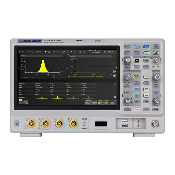
Quick Start Mechanical Dimension Front View Top View SDS2000X HD Quick Start... - Page 10 Adjust the Supporting Legs Adjust the supporting legs properly to use them as stands to tilt the oscilloscope upwards for stable placement as well as easier operation and observation of the instrument. Connecting to Power Supply The standard power supply for the instrument is 100~240 V, 50/60 Hz. Please use the power cord provided with the instrument to connect it to AC power.
-
Page 11: Front Of Oscilloscope
Front of Oscilloscope Touch Screen Display The USB 2.0 Host Ports Connect display and major functions to USB storage devices for area. See "User Interface" for data transfer more details mouse/keyboard for control Front Panel Includes knobs Digital Input Connector and buttons. -
Page 12: Back Of Oscilloscope
Back of Oscilloscope Ext Trigger Input USB 2.0 Device Connects with a PC for remote control Built-in Waveform Generator USB 2.0 Host Connect with a Output USB storage device or USB mouse/keyboard Auxiliary Out Outputs trigger indicator. When Mask AC Power Input Test is enabled, outputs the Handle pass / fail signal... -
Page 13: Probe Compensation
Probe Compensation All oscilloscope probes should be properly compensated before their first use with the oscilloscope. A non-compensated or inadequately compensated probe may cause inaccurate measurement. The following steps illustrate the proper probe compensation procedure. Use the probe to connect the CH1 Input Terminal and the Compensation Signal Output Terminal on the front panel. -
Page 14: User Interface
User Interface Menu Bar Grid Area displays the waveform traces. Traces can be moved by dragging them and re-scaled by pinch and spread Channel descriptor boxes include analog channels (C1 ~ C4), digital channels (D), math (F1-F2) and reference (Ref). They show the parameters of the corresponding traces. - Page 15 Channel Descriptor Box Channel Index Coupling and Input Impedance Vertical Scale Vertical Offset Bandwidth Information Probe Attenuation Factor Timebase and Trigger Descriptor Boxes Trigger delay Horizontal scale ( timebase ) # Samples Sample Rate Trigger source Trigger coupling Trigger mode Trigger level Trigger type Trigger slope...
- Page 16 Dialog Box The dialog box on the right side of the screen is the main area for setting the parameters of the selected function. Title bar. Touching the bar can hide the dialog box, and touching again can open the dialog box Parameter setting area Scroll bar.
- Page 17 To Set Parameters Several different ways are provided to set parameters: Switch – sets parameters with two states, such as to enable or disable a function. Touch the switch region to change from one state to the other. List – sets parameters with more than two options, such as the coupling mode of channels.
- Page 18 Touch Gestures Waveforms, cursors and trigger level can be adjusted by touch gestures in the grid area. Drag the waveform left and right to move it on the horizontal axis Pinch and spread the waveform horizontally to re-scale the timebase Drag the waveform up and down to move it on the vertical axis Pinch and spread the waveform...
- Page 19 Touch and drag the cursor to move it Touch drag cursor information region to move the pair of cursors simultaneously Draw a rectangular box to create a zone or a histogram region. At the beginning of the gesture keep the angle close to 45°...
- Page 20 Front Panel The front panel is designed to operate the basic functions without having to open the software menu. Most of the front panel controls duplicate functionality available through the touch screen display but the operation is more quickly achieved Automatically sets the waveform to adapt the display according to its frequency and amplitude...
-
Page 21: Basic Operations
Basic Operations Turn On / Disable a Channel From the Front Panel Push the channel button ( 1-4, Digital, Math, Ref ) to turn on the corresponding channel. Its channel descriptor box and dialog box will appear on the display. If a channel is already on but not activated, push the button to activate it. - Page 22 Channel Setup Touch the channel descriptor box, a quick dialog will pop up. Vertical scale and offset can also be set from this dialog box. Touch the region to set the vertical scale with the universal knob or virtual keypad ▲...
- Page 23 Activating a channel in the quick dialog of the channel recalls the channel dialog box, displaying more parameters: Turn channel on/off Coupling ( DC, AC or GND ) Bandwidth limit ( Full, 200 MHz or 20 MHz ) Probe attenuation ( 1X, 10X, 100X or custom ) Set the label text.
- Page 24 Horizontal System Rotate to adjust the horizontal scale ( time / div ); When Zoom is enabled, push to switch between the main window and zoom window Push to enable / disable Zoom Push to enable horizontal Roll; push again to exit Roll mode.
- Page 25 Acquisition System Touch on the quick menu of the timebase settings, or touch the menu bar Acquire > Menu to recall the Acquire dialog box on the right side. Select the interpolation mode Select the Acq mode Select the acquisition mode ( Normal / Peak / Average / ERES ) Select the Memory Management mode ( Auto, Fixed Sample Rate, and Fixed Memory )
- Page 26 Zoom Waveform zoom in the horizontal and vertical directions is supported. Push the button on the front panel to enable Zoom mode When the Zoom mode is enabled, Press down the horizontal knob to switch between the main window and zoom window. Currently activated window is high-lighted by dash line.
- Page 27 Trigger The trigger system supports multiple powerful triggering modes including serial bus triggering. Refer to the User Manual for more details. Opens trigger setup dialog box Auto mode – triggers after preset period if no valid trigger occurs Single-mode – triggers once when all conditions are met Normal mode –...
- Page 28 Select trigger type Select the trigger source Select the trigger slope ( When the trigger type is "Edge", "Slope" and other specific types ) Set holdoff ( None / Time / Events ) Set trigger coupling mode ( DC / AC / LF Reject / HF Reject ) Enable / disable Noise Rejection.
- Page 29 Math Touch + > Func1 / Func2 , or push the button on the front panel to create a math trace and open math setup dialog box Math trace Math setup dialog box Selects the trace (F1 ~ F2) Selects the operator and source (C1~C4, Z1~Z4, F1~F2) SDS2000X HD Quick Start...
- Page 30 Measure & Statistics Touch Measure > Menu , or push the button on the front panel to open measure setup dialog box Measurement parameters and statistics display area. If select the mode as “Simple”, the "Simple" parameter area is displayed. Touch the button on the front panel to reset the statistics Measure dialog box...
- Page 31 Cursors Cursors set measurement points on the Vertical or Horizontal axis of a trace (or both). For more information please refer to the User Manual. Push the button to open the cursors setup dialog box Rotate the knob to move the selected cursor; push to select different cursor The display mode of cursors Following...
- Page 32 Reference Waveforms Reference waveforms ( REFA, REFB, REFC, and REFD ) are analog or math traces stored in the non-volatile memory. They can be recalled to the display for comparison with other traces. Press the button on the front panel to set the reference waveforms.
- Page 33 Save/Recall Touch Utility > Save/Recall to save / recall a setup, picture, waveform data or reference waveform. Choose Save or Recall operation Select the object type Recall the File Manager for further operations File Manager Quickly Save Push the button on the front panel to perform specified save action. The Utility >...
- Page 34 Quick Action Push the button on the front panel to perform a specified action. Touch > Utility Quick Action to open the Quick Action menu and set the action mapping to the button. By default, Quick Action is disabled, and pushing the button for the first time will open the Quick Action menu.
- Page 35 Changing vertical scale or channel interleaving mode will initiate the same ADC calibration procedure in the background. This is always enabled, regardless of the status of Quick Cal. Touch Utility > Menu > Maintenance > Quick Cal to set Quick Cal. Software Option Installing a Software Option Follow the steps below to install a software option ( see the data sheet for details )
- Page 36 DC power supplies, electronic loads and other general purpose test instrumentation. Since its first oscilloscope was launched in 2005, SIGLENT has become the fastest growing manufacturer of digital oscilloscopes. We firmly believe that today SIGLENT is the best value in electronic test & measurement.
Need help?
Do you have a question about the SDS2354X HD and is the answer not in the manual?
Questions and answers