Table of Contents
Advertisement
Quick Links
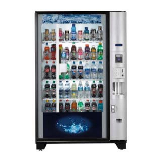
Glassfront BevMax 3 5800-4 Vender
Model DN5800 - 4
Production Run 8882AH & higher
No 24oz
Sport Cap
Bottles
Manufactured by
Operation
Service
Parts
Troubleshooting
Manual
Dixie-Narco, Inc.
P.O. Drawer 719
Williston, SC 29853-0719
803-266-5001
fax: 803-266-5049
Visit us on the web:
www.dixienarco.com
803,904,620.11
Advertisement
Table of Contents

Related Manuals for Crane Dixie Narco Glassfront BevMax 3


Summary of Contents for Crane Dixie Narco Glassfront BevMax 3
- Page 1 Glassfront BevMax 3 5800-4 Vender Model DN5800 - 4 Production Run 8882AH & higher No 24oz Sport Cap Operation Bottles Service Parts Troubleshooting Manual Dixie-Narco, Inc. P.O. Drawer 719 Manufactured by Williston, SC 29853-0719 803-266-5001 fax: 803-266-5049 Visit us on the web: www.dixienarco.com 803,904,620.11...
-
Page 2: Table Of Contents
Table of Contents GENERAL INFORMATION.................. 4 Vender Safety Precautions....................4 Product Identification ......................4 Physical Characteristics ......................4 INSTALLATION & SETUP................4 - 9 Receiving Inspection ......................4 Unpacking The Vender....................4 - 5 Electrical Requirements.......................5 Power Supply & Grounding Requirements..............5 - 6 Installation &... - Page 3 Picker Cup at Wrong Location X Axis Flow Chart .............41 Delivery Port Door Flow Chart...................42 Coin Acceptance........................43 Bill Acceptors ........................43 Control Board........................43 All Coins Rejected Flow Chart...................44 All Bills Rejected Flow Chart .....................45 Incorrect Change Dispensed Flow Chart ................46 Selection Will Not Vend Flow Chart...................47 Ice / Frost on Evaporator Flow Chart.................48 Condensate on Outside of Product Door Flow Chart ............48 Compressor Will Not Stop Flow Chart................48...
-
Page 4: General Information
VENDER SAFETY PRECAUTIONS PHYSICAL CHARACTERISTICS Please read this manual in its entirety. This service DN5800-4 information is intended for use by a qualified service technician who is familiar with proper and safe 72” (1828.8 mm) HEIGHT procedures to be followed when repairing, replacing or adjusting any Dixie-Narco vender components. -
Page 5: Electrical Requirements
into the plug or mounted on the cord adjacent to the plug. WARNING: TO AVOID THE POSSIBILITY FIRE WARNING HAZARD, DO NOT STORE • The GFCI protects against current ANYTHING ALLOW leakage caused by ground faults. DEBRIS OF ANY KIND TO The GFCI is not designed to protect ACCUMULATE against over current or short... -
Page 6: Installation & Setup Instructions
provided with the machine. DO NOT USE THE TO OPEN THE ELECTRONIC DOOR LOCK: VENDING MACHINE UNTIL THE WORN OR 1. Plug the vender into a properly powered DAMAGED CORD IS REPLACED. outlet. FAILURE TO COMPLY WITH 2. Hold the key FOB 0 to 3 inches in front of the THESE INSTRUCTIONS MAY Delivery Port Door and press the button on SUBJECT THE USER TO THE RISK... -
Page 7: Placing The Vender On Location
acceptor should cycle twice). The display on the door pallet jack or Vender/Cooler Dollies at all times when will briefly show the software version in use as moving the Vender. The vender should never be slid “Software ###.## (ie 70#.#1) followed by the default or pushed in place. -
Page 8: Installing Labels & Product Id Cards
WARNING SETTING THE TEMPERATURE TO AVOID THE POSSIBILITY OF A CONTROL FIRE HAZARD, DO NOT STORE This vender equipped with electronic ANYTHING OR ALLOW DEBRIS OF temperature sensor. Defrost is controlled both ANY KIND TO ACCUMULATE IN THE electronically based on run time of the compressor BOTTOM OF THE DOOR, IN THE and with a manual Defrost thermostat. -
Page 9: Power Ac Distribution Box
fill/dispense mode in the test menu. (see control of the thermostat is attached to the evaporator page 19 in the programming section for more coils and reads the temperature of air being pulled in information). to the evaporator coil. For additional information about coin mechanism, refer to the manufacturer’s instructions. -
Page 10: Deliver (Picker) Cup Assembly
DELIVERY (PICKER) CUP ASSEMBLY The delivery (picker) cup assembly is located on the XY vend mechanism. Its purpose is to pick the product from the column and deliver the product to the delivery port assembly. The delivery (picker) cup assembly is mounted on the XY assembly and bolts in position. -
Page 11: Programming
“ENJOY A REFRESHING DRINK AND SNACK” when attached to a snack vender.. PROGRAMMING INITIAL PROGRAMMING GENERAL INFORMATION In order to fully utilize the many features of your vender it is important that you first understand the DATE/TIME options available and procedures for programming the To set date/time enter “SETUP MODE 1”... - Page 12 “ ” and display will show “PR $##.## B(tray settings, Key 2 for Select Block 2, etc… Once you letter) Row Set”, press “*” to set more prices select the Select Block # you wish to set the display or CLR to return to SET PRICES. Press CLR will show “Start MTWTFSS Stop 1 00:00 NNNNNNN Key again to return to SERVICE MODE.
-
Page 13: Quick Reference Menu Items
BevMax 3 5800-4 Z Board Programming Service Mode Test Mode Setup Mode 1 Setup Mode 2 Satellite Mode (Multimate) A Step through below Step through below Step through below Step through below Step through below B Cash Box List Errors Enter Message STS Enabled/Disabled (not used) -
Page 14: Service Mode
selected Display will change “Set Temperature Unit Degrees F (or C) showing the SERVICE MODE MENU ITEMS current setting temperature will be displayed. Press Note: Menu items with the ** are not currently F for Fahrenheit or C for Celsius. Press the available. - Page 15 1. Pressing the “ ” key will toggle between FORCE VEND - Press key “5” enabled and disabled for the entire machine, Forces the customer to make a vend by inhibiting the display will show the new state i.e. the coin return lever once the minimum vend price enabled or disabled and display will show line has been met or exceeded The coin return lever “Blocked (Unblocked) Continue?
-
Page 16: Test Mode
B(tray letter) Row Set”, press “*” to set more relay operates). To toggle the state of a given relay prices or CLR to exit to SET PRICE. press the letter key associated with it on the display. 3. Single selection. Press the keypad Caution: Disconnect power to the compressor before numbers of the price you wish to use. - Page 17 LB – Low battery. KEYPAD TEST - Press key “E” CTRL PWR OUT – Power lost. Allows the service technician to test any or all KEYPAD ERROR keypad keys. Press the letter “E” on the keypad and KEYPAD – Keypad not installed. the display will show “KEYPAD TEST”.
- Page 18 setting. Cup Sensor On is used in all BevMax 3 In:0 Out:0 Hm:1”. To perform tests press the 5800-4 Venders produced 3/26/08 and after. following: • Key 1 = Position Test. Note: The left or top door a. Shelf letter (A,B,C,D,E) to travel to switch (depending on the mounting bracket in selected shelf.
- Page 19 return to “Factory Diagnostics”. Press “CLR” LED on the controller also will be on key to return to “Test Mode”. Then go to “Test when a “1” is displayed. Vend” and test for proper delivery of product in the Port Assy. of the Service Door. “Hm”...
- Page 20 • Press the “CLR” key to return to “Door Open”. Press Australian Rules. If enabled, the VCU will the “CLR” key to return to “TEST MODE” or press set the clock back one hour on the last the “A” key to advance to the next menu item below. Sunday of March (1:00 AM), set the clock ahead one hour on the first Sunday in October (1:00 AM).
-
Page 21: Setup Mode 1
The “A” key will move forward through the alphabet, TEST VEND - ” Press key “9 numbers, space, punctuation marks, $, AND an “L”. Allows the service technician to test vend any item. The “B” key will move backwards through the same The service door must be closed or open all the way list. - Page 22 MASTER RESET - SOLD OUT TIMES CLEARED Press key “F” DEX PASSWORD 000000 (PASSWORD REQUIRED) DOOR OPEN TIME CLEARED Allows the service technician to restore factory POWER OUT TIME CURRENT TIME defaults to the machine or reset the Controller STORAGE TEMP 57 DEG F Board’s memory after installing a new EPROM.
- Page 23 to “SETUP MODE 1” or press the “A” key to advance Continue? = Y CLR = N. When enabled to the next menu item below. desired selection will now be set for health control. For example, to control the A1 push DATE/TIME keys “A1”...
-
Page 24: Setup Mode 2
c. Verify the pins of the new Eprom are ENTER NEW PASSWORD - Press key “0” not bent before installing in the (PASSWORD REQUIRED) Eprom socket. Allows the service technician to enter a 4 number d. Install the new Eprom in the Eprom personalized password. - Page 25 previously defined Space-to-Sales “SOLD OUT”. Press the “F” key on the keypad. The blocks. display will show “SET NOVEND LIMIT”. Press the 2. Pressing a tray selection followed by “ ” will “ ” key and the display will show” NOVEND LIMIT configure an entire tray as a single Space- #”.
-
Page 26: Satellite (Multimate) Mode
two separate displays. Press the number “4” on the same manner as “SET NOT AVAIL TIME” covered in keypad and display will show “Price Display”. Press the Initial Programming Section of this manual. the “ ” Key and display will show “Price Display: On (Off). - Page 27 display will show Total Number XX, where XX is the “ ” PR $ on the display. Press the key the display total number of Combo Discount vends. Press the “ ” will ask “ALL Prices Set Ok?” Press the key to “...
-
Page 28: Major Component Description
♦ When enabling or disabling single selections the Transformer (T1) Provides Volt power opposite state of the current setting will be used. For Controller Board. example: if you currently have selection 210 enabled and you go into change it, it will change to disabled. ♦... -
Page 29: Cleaning
Repair any scratches on painted surfaces to CLEANING prevent corrosion. DO NOT USE A WATER JET OR NOZZLE TO CLEAN THE VENDER DRAIN PAN, DRAIN TUBE, AND DRAIN HOSE To prevent mold and mildew growth, GLASS DOOR and to avoid personal injury or The display glass should be cleaned inside and property damage, the drain pan, out with paper towels and glass or non-abrasive... -
Page 30: Control Board
P10A BevMax 3 5800-4 J11A J12A BEVMAX 3 5800-4 Z++ MDB CONTROLLER CONNECTIONS CONNECTION CONNECTION CONNECTION CONNECTION DESCRIPTION DESCRIPTION NOT USED PEPSI/GENERIC NOT USED PEPSI/GENERIC Power from AC Fuse Distribution Box Cup Signal & Y Encoder X Motor & Encoder J11A Keypad Product Port... -
Page 31: Troubleshooting
BEVMAX 3 5800-4 TROUBLESHOOTING “XY” ISSUES 1. Selection will not vend. a. Does a different selection vend? i. Perform TEST VEND in TEST MENU ensure proper selection vends. ii. Check Custom Space-To-Sales has been enabled. 1. Check STS configuration in SETUP MODE 2 Menu. b. - Page 32 a. Check error list. Does error list show “VEND ERR”, with selection included in vend error list when pressing “A”? b. A previous vend operation or vend test failed. 2. Software has selection identified as “sold out”. 3. Selection is placed under SETUP MODE, HEALTH GUARD. 4.
- Page 33 2. At the home position the “X” (top far left) home switch will light an amber LED on the control board. a. Adjust the X drive belt. d. Check the Delivery Cup Plunger & Plunger Home Switch i. If plunger arm is stuck out it will shut down XY delivery system. ii.
-
Page 34: Xy Not Working Flow Chart
XY not Is P1 connected to control board? Is vender plugged in? working Plug in Vender. Are P3 & J3 connected Go to Factory to control board? Diagnostics. Plug in connector. Visual check. Where is picker cup located? HOME NOT HOME Check top door switch working? Manually RED light is... -
Page 35: Plunger Home (Red Light) Flow Chart
Plunger Home = Red light Check X Home = Visual check. Where is picker cup Yellow light. located? HOME NOT HOME In position test. Press “0” key to cycle Cycle plunger multiple times to plunger. Is Red LED ensure proper operation. If Plunger is stuck in the out or in position. -
Page 36: Axis Home (Yellow Light) Flow Chart
X Axis Home = Yellow light Check Y Home = Manually activate the switch Green Light and light cycles on and off. Manually move cup to A9 and pull top door switch out. Check, repair, or replace switch or harness. Problem solved? Press the “F”... -
Page 37: Y Axis Home (Green Light) Flow Chart
Y Axis Home = Green light Check All Home LED’s are on. Manually activate the switch and light cycles on and off. Manually move cup to A9 and pull top door switch out. Check, repair, or replace switch or harness. Problem solved? Press the “F”... -
Page 38: Xy Slams To Top/Right Or Left Flow Chart
XY Slams to Top/ Right 0r Left Go to Diagnostics Do a test vend with door closed. Do the Encoder counts increase & decrease when moving the Manually move XY manually? Pull top door Picker Cup to “A9” switch out. position. -
Page 39: Picker Cup Not Working Flow Chart
Is vender plugged in? Is P1 connected to Picker Go to Factory control board? Diagnostics. Cup not working Plug in Vender. Plug in connector. Visual check. Where is picker cup located? HOME NOT HOME Is plunger below target? Is plunger touching target? Is plunger Go to “A”... -
Page 40: Picker Cup At Wrong Location Y Axis Flow Chart
CUP AT WRONG LOCATION HIGH/LOW or Y AXIS Is shelf setting correct? Go to Factory Diagnostics. Check encoder counts. Send to home, does home switch light come on? Send cup to “A9” position. Press “F” to go home. Did green light flicker? Check, repair, See XY not or replace X... -
Page 41: Picker Cup At Wrong Location X Axis Flow Chart
CUP AT WRONG LOCATION LEFT /RIGHT or X AXIS Go to Factory Diagnostics. Check encoder counts. Send to home, does home switch light come on? See XY not Send cup to home working page position. Does it go home? Send cup to “E2-E8” See X Axis positions. -
Page 42: Delivery Port Door Flow Chart
DELIVERY PORT DOOR WORKS IN FACTORY DIAGNOSTICS BUT NOT IN SALES MODE Close door and do a test vend. Does it work? Open service door. Pull top door switch out and do a test vend. Does it work? Check, repair, and replace door switch components: mounting Go to Factory Diagnostics,... -
Page 43: Coin Acceptance
COIN ACCEPTANCE ISSUES PROBLEM CAUSE Coins Returned to Customer 1. Coin Jam in Mech 1. Clear Jam and Test With No Credit Issued 2. Flight Deck Dirty 2. Clean Flight Deck 3. No Power to Mech 3. Check Harness, Changer to 4. -
Page 44: All Coins Rejected Flow Chart
These charts are intended as a guide to isolate and correct most problems you might encounter. Should your machine show ‘OUT OF SERVICE”, go in the TEST MODE and press “B” to list errors. ALL COINS ARE REJECTED All coins are rejected. Main Power OFF / Apply power Disconnected. -
Page 45: All Bills Rejected Flow Chart
ALL BILLS ARE REJECTED All bills are rejected. Main Power OFF / Apply power Disconnected. Check fuses and Blown Fuse replace if necessary. List errors to determine Machine is Out Of cause of Out Of Service. Service. Refer to programming for error explanations. -
Page 46: Incorrect Change Dispensed Flow Chart
INCORRECT CHANGE DISPENSED Incorrect change dispensed. Check price and Vend prices set reset if incorrectly. necessary. Check coin Coins not laying flat in tubes; clear and tubes. reload coins. Defective coin Replace. mechanism. Defective controller Replace. board. -
Page 47: Selection Will Not Vend Flow Chart
SELECTION WILL NOT VEND Selection will not vend. Check price and Vend price set incorrectly. reset if necessary. Check price, ensure credit is Insufficient credit. equal to or greater. Product and gate mis- Check gate / matched. spacer. Move product away from gate (removing the weight) and use "Test Vend"... -
Page 48: Ice / Frost On Evaporator Flow Chart
ICE / FROST ON EVAPORATOR Ice / frost on evaporator. Condensate drain Clear drain. plugged. Check product door Air leak. seal and cable openings in cabinet. CONDENSATE ON OUTSIDE OF PRODUCT DOOR Condensate on outside of product door. Machine in direct Move machine. -
Page 49: Compressor Will Not Start Flow Chart
COMPRESSOR WILL NOT START Compressor will not start. Close service Service door open. door. Plug compressor in Compressor is outlet on face of unplugged. AC distribution box. Defective door interlock Replace switch. Check power Low voltage. source. Defective thermostat. Replace. Defective starting component (capacitor, Replace. -
Page 50: Machine Not Cooling Flow Chart
MACHINE NOT COOLING Machine not cooling. Dirty or clogged Clean. condenser. Defective thermostat. Replace. Check rear screen for Check rear screen for obstructions. obstructions. Ensure rear of Restricted airflow. Ensure rear of cabinet is at least 4” cabinet is at least 3.25" (82.6 mm) from wall. -
Page 51: Electrical Diagrams & Schematics
BevMax 3 5800-4 Domestic Block Diagram Motor Power Interrupt Switch X Motor Lamp X Home Switch Door Switch E Lock Door Relay Lamp Y Motor E lock Aux. E Lock Lamp Power Y Home Switch Ballast Cup Motor Plunger in Relay Control 120 VAC switch... -
Page 52: Block Diagram Export
BevMax 3 5800-4 Export Block Diagram X/Y Power Interrupt Switch X Motor Lamp X Home Switch Door Switch E Lock Door Relay Lamp Y Motor E lock Aux. E Lock Lamp Power Y Home Switch Ballast Cup Motor Plunger in 220 VAC Relay Control (24 VDC) switch... -
Page 53: Vender Wiring Diagram Cabinet (Domestic & Export)
BevMax 3 5800-4 Cabinet Diagram (Domestic & Export) Y Motor 80450184xx1 Y Motor Y Motor Board 80492354xx1 Limit Switch 80410122xx1 80492826xx1 80492374xx1 To P14/P8 control board 80492479xx1 Cup Home Sw. 80410122xx1 Picker Out Sw. 80410126xx1 Picker Home Sw. 80410123xx1 Picker Motor 80450139xx1 Cup Board 80492765xx1... - Page 54 BevMax 3 5800-4 5800-4-4 Cabinet Diagram (Domestic & Door Door Switch Switch 80492824xx1 80492823xx1 80492836xx1 To Door 80492826xx1 To P3/P6 Y Motor board To Coin Mech To DEX 80492827xx1 80492825xx1 Jack Z Control Board 80492772xx1 To X Motor 80492819xx1 Temp Sensor 80492821xx1 80492819xx1 80492828xx...
-
Page 55: Vender Wiring Diagram Door (Domestic & Export)
BevMax 3 5800-4 Door Diagram (Domestic & Export) 80492836xx1 To Cabinet 80492475xx1 To Cabinet To MDB Port Peripherals Motor Display Electronic Port Board 80492386xx1 lock 80492508xx1 IRDA 80492411xx1 Port Auxiliary Lock Power Vend Sensor Board Keypad 80492749xx1 80410121xx1... -
Page 56: Vender Wiring Diagram Power & Lighting (Domestic Only)
BevMax 3 5800-4 Domestic Power & Lighting Diagram 80492755xx1 80492754xx1 Relays (3) 80492819xx1 8090026xx1 Light, fan, & compressor Ballast Ballast 80492755x 80440071xx1 AC Distribution Box Transformer Lamp 80492514xx1 To Cabinet Light relay To Evaporator Fan Fan relay BLK/BRN WHT/BRN Choke 80492042xx1 Comp. -
Page 57: Vender Wiring Diagram Power & Lighting (Export Only)
BevMax 3 5800-4 Export Power & Lighting Diagram... -
Page 58: Compressor Parts Diagram
BevMax 3 5800-4 Compressor Parts Diagram Domestic Compressor Parts BevMax 3 5800-4 Item Part # Description 802,502,88x.x1 Compressor, Embracco FFU130HAX 115/60 (EM# 513200620) 802,402,17x.x1 Bracket, Capacitor FFU130HAX (EM#US-2255008) 802,402,13x.x1 Overload, Compressor FFU130HAX (EM#513554617) 802,402,14x.x1 Cover, Electrical Component FFU130HAX (EM#13555028) 802,402,16x.x1 Relay, Compressor Start FFU130HAX (EM#213516051) 802,402,18x.x1 Capacitor, Compressor Start FFU130HAX (EM#US-3252378) -
Page 59: Ac Distribution Box Connector Voltages
BevMax 3 5800-4 AC Distribution Box Domestic AC Box Shown Domestic Test Voltages 9 Pin J2 Output Power Connector lead lead Domestic Reading to Pin 24 (26 to 30) VAC secondary of transformer 24 (26 to 30) VAC secondary of transformer ground 110 VAC Hot not switched for 1 lamp assy. -
Page 60: Parts List And Diagrams
PARTS LIST PARTS LIST AND DIAGRAMS..............60 – 90 Machine Front View....................61 – 62 Cabinet Detail Product Area ..................63 – 64 Cabinet Detail Service Door Area ................65 – 66 XY Motor Picker Unit ....................67 – 68 Picker Cup Assembly ....................69 – 70 Service Door Outside ....................71 –... -
Page 61: Machine Front View
MACHINE FRONT VIEW... - Page 62 MACHINE FRONT VIEW ITEM PART DESCRIPTION DN5800-4 Door Assembly, Glass 800,105,95x.x1 Gasket, Glass Door 800,102,58x.x1 Top Hinge Glass Door 657,010,90x.x3 Carriage Bolt – ¼ - 20 x 1 1/4 800,202,43x.x1 Hex Nut – ¼ - 20 800,801,57x.x1 Washer, Flat 800,701,44x.x1 Top Hinge Service Door CR0002256 Carriage Bolt, 1/4 –20 X 2.5”...
-
Page 63: Cabinet Detail Product Area
CABINET DETAIL PRODUCT AREA... - Page 64 CABINET DETAIL PRODUCT AREA ITEM PART DESCRIPTION 5800-4 5800-4 Domestic Export Cabinet Assembly, Generic 657,060,20x.x3 Left Tray, BevMax 3 5800-4 Mount Bracket 647,070,05x.x3 Left Tray Rail, BevMax 5800-4 657,070,030.03 Right Tray, BevMax 3 5800-4 Mount Bracket 647,070,04x.x3 Right Tray, Rail, BevMax 5800-4 657,070,010.03 Rear Tray Rail, BevMax 5800-4 657,070,020.03...
-
Page 65: Cabinet Detail Service Door Area
CABINET DETAIL SERVICE DOOR AREA... - Page 66 CABINET DETAIL SERVICE DOOR AREA ITEM PART DESCRIPTION DN5800-4 DN5800-4 Domestic Export Coin Mech Housing Assembly 647,001,00x.x3 Lower Coin Chute Assembly 801,823,42x.x1 Lower Coin Chute Part of #2 Lower Coin Chute Cover Part of #2 Cash Box Clip 801,814,68x.x1 Assembly, Lever Mech Arm Coin Return 647,003,20x.x3 Assembly, Lever Button Rod 647,003,10x.x3...
-
Page 67: Xy Motor Picker Unit
XY MOTOR PICKER UNIT... - Page 68 XY MOTOR PICKER UNIT ITEM PART DESCRIPTION DN5800-4 XY Delivery System CR0002183 Assembly Cover Y Belt CR0001797 Y Motor Cover Top 801,823,29x.x1 X Motor Cover Bottom 801,823,28x.x1 X Bottom Belt Cover (Ramp) CR0002585 Harness, X Motor – bottom, not shown 804,928,25x.x1 X Top Carriage Assembly (top of XY) CR0002121...
-
Page 69: Picker Cup Assembly
DELIVERY (PICKER) CUP ASSEMBLY... - Page 70 DELIVERY (PICKER) CUP ASSEMBLY ITEM PART DESCRIPTION DN5800-4 Assembly Delivery (Picker) Cup Assembly 647,082,70x.x3 Cup Base Board (Picker Cup Board with sensor) 3/26/08 & after 804,927,65x.x1 Cup/Port Motor Assembly 804,501,61x.x1 Cup Motor Cam 801,202,02x.x1 Micro Switch with Bent Arm (Picker Home Switch) 804,101,37x.x1 Micro Switch with Straight Arm (Cup Home Switch –...
-
Page 71: Service Door Outside
SERVICE DOOR (OUTSIDE) - Page 72 SERVICE DOOR (OUTSIDE) ITEM PART DESCRIPTION DN5800-4 Service Door Assembly, Gray (need to order item 23 separately) Service Door Assembly, Black (need to order item 23 separately) Weld Assembly Service Door CR0001802 Assembly Bezel Top, Gray CR0004307 Assembly Bezel Top, Card Reader Gray Assembly Bezel Top, Black Assembly Bezel Top, Card Reader Black Bezel Center, Gray...
-
Page 73: Service Door Inside
SERVICE DOOR (INSIDE) - Page 74 SERVICE DOOR (INSIDE) ITEM PART DESCRIPTION DN5800-4 Display Lens, Blue (part of top bezel assy) Screw, Nylon Circuit Board Support CR0002205 Assembly Display (Noritake) 804,923,86x.x1 Rod, Latch Bar 647,050,03x.x3 Door Harness 804,928,36x.x1 Extended Coin Return Cup Assembly 801,824,29x.x1 Change Cup Part of #6 Change Cup Door Part of #6...
-
Page 75: Gate Tray Detail
GATE TRAY DETAIL... - Page 76 GATE TRAY DETAIL ITEM PART DESCRIPTION DN5800-4 Tray Assy., 9 Column 657,070,00x.x3 Chassis Tray, Tall Gate 647,071,50x.x3 Double Gate Assembly 801,820,18x.x1 Double Gate Assembly Right 801,820,29x.x1 Double Gate Assembly Left 801,820,31x.x1 Spring Gear Box Part of #7 Gear Box Assembly 801,820,62x.x1 Double Gate Drive Mech Target Part of #7...
-
Page 77: Ac Distribution Box
AC DISTRIBUTION BOX Export AC Box Not Shown To Be Determined Domestic AC Box Shown board relays... - Page 78 AC DISTRIBUTION BOX ITEM PART DESCRIPTION DN5800-4 DN5800-4 Domestic Export Assembly AC Distribution Box, BevMax 5800-4-4 657,070,70x.x3 Transformer, 120V / 24V, 60 Hz, 8A Domestic 804,925,14x.x1 Transformer, Export Outlet, 15 Amp, Grounded W662 Power Inlet Plug 804,913,62x.x1 Harness, AC Power In 804,928,43x.x1 Harness, Power Distribution 804,928,42x.x1...
-
Page 79: Lighting
LIGHTING ITEM PART DESCRIPTION DN5800-4 DN5800-4 Domestic Export Horizontal (Upper) Light Assembly (1 Lamp) 657,012,10x.x3 Ballast Assembly, T8 Electronic 110V/60Hz (Horizontal Lamp) – 2 804,401,26x.x1 pin connector Lamp Cover (22.6”) & End Caps 801,904,77x.x1 Light Harness, 120 Volt – 1 Lamp T8 (Upper Light Assy.) 804,928,52x.x1 Lamp Holder, T8 Bi Pin - Leviton 23653 (Horizontal) Use 4... -
Page 80: Refrigeration Unit Fin & Tube Condenser
REFRIGERATION UNIT (BevMax 3 5800-4 FIN & TUBE CONDENSER) - Page 81 REFRIGERATION UNIT (BevMax 3 5800-4 FIN & TUBE CONDENSER) ITEM PART DESCRIPTION DN5800-4 DN5800-4 Domestic Export Refrigeration Unit DN2008-C, 115V/60Hz Domestic 657,040,000.13 Refrigeration Unit DN#### C-A Kit, 220V/50Hz Export Kit Compressor Assy. FFU130HAX , 115V/60Hz Domestic 802,502,890.01 Compressor Assy. 220-240V/50Hz Export Compressor, Domestic (Embracco 513200620) 802,502,88x.x1 Compressor, Export...
-
Page 82: Electronics
ELECTRONICS Pepsi/Generic BM3 5800-4 New Z++ Control Board... - Page 83 ELECTRONICS ITEM PART DESCRIPTION DN5800-4 DN5800-4 Domestic Export BevMax 3 5800-4 Control Board Assembly, Z 804,928,70x.x1 BevMax 3 5800-4 Control Board Assembly Standoffs, .8 – 32 x 5/8 801,001,75x.x1 EPROM, Firmware, BevMax 3 5800-4 Z Plus Board 804,927,70x.x1 Display Assembly (Noritake) 804,923,86x.x1 Transformer 804,925,14x.x1...
-
Page 84: Harnesses
HARNESSES... - Page 85 HARNESSES DN5800-4 DN5800-4 ITEM PART DESCRIPTION FROM/TO Domestic Export Harness, Electronic Lock 12 pin plug to E Lock board 804,923,41x.x1 (E-lock venders only) 2 connectors to door switch 1 jack in top of port 2 pin cap to top port lock board Harness, Key Sensor Phone jack to top port lock board (TriTeq supplied only) Black &...
-
Page 86: Labels / Decals / Misc
LABELS / DECALS / MISC. ITEM PART DESCRIPTION DN5800-4 Vender Lag Bracket Kit 627,020,60x.x4 Thermometer 801,401,55x.x1 Price Sheet .35 – 1.10 803,877,51x.x1 Price Sheet 1.15 – 1.85 803,877,52x.x1 Price Sheet 1.90 – 3.75 803,877,53x.x1 Label, Selection - BevMax 3 5800-4 (A1 to E9) 803,857,26x.x1 Label, Warning “DO NOT TILT”... -
Page 87: Screws & Nuts
SCREWS & NUTS... - Page 88 SCREWS & NUTS ITEM PART NUMBER PART NAME AND DESCRIPTION 800,304,46x.x1 Screw, Phil Pan Head 1/4 - 20 x 1 ¼" 800,304,22x.x1 Screw, Phil Pan #8 - 32 x 3/8" 800,304,18x.x1 Screw, Phil Pan w/out washer self drilling, #8 - 18 x 1/2" 800,304,34x.x1 Screw, Phil Pan Swage Form #8 - 32 x 1/4"...
-
Page 89: Washers, Bolts, & Misc. Hardware
WASHERS, BOLTS, & MISC. HARDWARE... - Page 90 WASHERS, BOLTS, & MISC. HARDWARE ITEM PART NUMBER PART NAME AND DESCRIPTION 800,701,56x.x1 Washer, Lock .261 ID 800,701,39x.x1 Washer, Nylon .189 x .375 x .031 900,701,22x.x1 Washer, .260 ID x .687 OD Flat 901,503,08x.x1 Washer, Hex #29-34 (T-Handle) 800,701,52x.x1 Washer, .191 ID x .5 OD x .054T Flat 48909130 Washer, SS Flat #10 800,701,44x.x1...
Need help?
Do you have a question about the Dixie Narco Glassfront BevMax 3 and is the answer not in the manual?
Questions and answers