Table of Contents
Advertisement
Quick Links
Advertisement
Table of Contents

Related Manuals for Supero 1122GG-TF


Summary of Contents for Supero 1122GG-TF
- Page 1 UPER ® A+ Server 1122GG-TF USER’S MANUAL Revision 1.0a...
- Page 2 The information in this User’s Manual has been carefully reviewed and is believed to be accurate. The vendor assumes no responsibility for any inaccuracies that may be contained in this document, makes no commitment to update or to keep current the information in this manual, or to notify any person or organization of the updates.
- Page 3 Preface About This Manual This manual is written for professional system integrators and PC technicians. It provides information for the installation and use of the A+ Server 1122GG-TF. Installation and maintenance should be performed by experienced technicians only. The A+ Server 1122GG-TF is a 1U rackmount server based on the SC118GTS-1400BP server chassis and the Supermicro H8DGG-QF serverboards.
- Page 4 A+ Server 1122GG-TF User's Manual Chapter 6: Advanced Chassis Setup Refer to Chapter 6 for detailed information on the SC118GTS-1400BP 1U rackmount server chassis. You should follow the procedures given in this chapter when installing, removing or reconfiguring SATA or peripheral drives and when replacing system power supply units and cooling fans.
-
Page 5: Table Of Contents
Preface Contents Chapter 1 Introduction Overview ......................1-1 Serverboard Features ..................1-2 Processors ...................... 1-2 Memory ......................1-2 Serial ATA ......................1-2 PCI Expansion Slots ..................1-2 Ethernet Ports ....................1-2 Onboard Controllers/Ports ................1-3 Graphics Controller ..................1-3 Other Features ....................1-3 Server Chassis Features ................ - Page 6 A+ Server 1122GG-TF User's Manual Installing and Removing the Server ..............2-8 Installing the Server into a Telco Rack ............2-9 Checking the Serverboard Setup ..............2-10 Checking the Drive Bay Setup ...............2-11 Chapter 3 System Interface Overview ......................3-1 Control Panel Buttons ..................
- Page 7 Preface Processor and Heatsink Installation..............5-3 Installing a Passive CPU Heatsink ..............5-5 Removing the Heatsink ................... 5-5 Installing Memory .................... 5-6 DIMM Module Population Configuration ............ 5-8 Serverboard Details ..................5-9 H8DGG-QF Quick Reference ............... 5-10 Connector Definitions ..................5-11 Jumper Settings ....................
- Page 8 A+ Server 1122GG-TF User's Manual System Fans ....................6-13 Fan Numbering in the BIOS ................ 6-13 System Fan Failure ..................6-14 Power Supply ....................6-15 Power Supply Replacement ................6-15 Chapter 7 BIOS Introduction ...................... 7-1 Main Menu ...................... 7-2 Advanced Settings Menu ................
-
Page 9: Chapter 1 Introduction
Introduction Overview The A+ Server 1122GG-TF is a 1U server comprised of the SC118G-1400B chas- sis and a H8DGG-QF serverboard. Please refer to our web site for information on operating systems that have been certified for use with the server (www.supermicro. -
Page 10: Serverboard Features
PCI Expansion Slots The H8DGG-QF serverboard has two PCI-Express 2.0 x8 (in a x16) slots and three PCI-Express 2.0 x16 slots. In the 1122GG-TF server configuration, a riser card is pre-installed to support expansion cards. The serverboard supports two double-width graphic processor units (GPUs) in place of the full-height, full-width expansion cards. -
Page 11: Onboard Controllers/Ports
Chapter 1: Introduction Onboard Controllers/Ports Onboard I/O backpanel ports on each serverboard include one COM port, a VGA port, two USB ports, a dedicated IPMI LAN port and two Gigabit LAN (NIC) ports. Graphics Controller The H8DGG-QF features an integrated Matrox G200eW graphics chip, which in- cludes 16 MB of DDR2 memory. - Page 12 A+ Server 1122GG-TF User's Manual Figure 1-1.SR5690/SP5100 Chipset: System Block Diagram Note: This is a general block diagram. Please see Chapter 5 for details. DIMM A1 DIMM A1 HT3 Link DIMM A0 DIMM A0 DIMM B1 8x8-6.4GT/s DIMM B1 DIMM B0...
-
Page 13: Server Chassis Features
Chapter 1: Introduction Server Chassis Features Drives The SC118G chassis includes six 2.5" drive bays, that can accomodate hot-swappable SATA drives. System Power The SC118G features a Gold Level 1400 W high-efficiency power supply. See Chapter 6 for details. Front Control Panel The control panel provides a system monitoring and control interface. -
Page 14: Contacting Supermicro
A+ Server 1122GG-TF User's Manual Contacting Supermicro Headquarters Address: Super Micro Computer, Inc. 980 Rock Ave. San Jose, CA 95131 U.S.A. Tel: +1 (408) 503-8000 Fax: +1 (408) 503-8008 Email: marketing@supermicro.com (General Information) support@supermicro.com (Technical Support) Web Site: www.supermicro.com Europe Address: Super Micro Computer B.V. -
Page 15: Chapter 2 Server Installation
Chapter 2: Server Installation Chapter 2 Server Installation Overview This chapter provides a quick setup checklist to get your A+ Server up and running. Following these steps should enable you to have the system operational within a minimum amount of time. This quick setup assumes that your system has come to you with the processors and memory preinstalled. -
Page 16: Warnings And Precautions
A+ Server 1122GG-TF User's Manual the back of the rack to allow for sufficient airflow and ease in servicing.This product is for installation only in a Restricted Access Location (dedicated equipment rooms, service closets and the like). • This product is not suitable for use with visual display work place devices acccording to §2 of the the German Ordinance for Work with Visual Display... -
Page 17: Rack Mounting Considerations
Chapter 2: Server Installation Rack Mounting Considerations Ambient Operating Temperature If installed in a closed or multi-unit rack assembly, the ambient operating tempera- ture of the rack environment may be greater than the ambient temperature of the room. Therefore, consideration should be given to installing the equipment in an environment compatible with the manufacturer’s maximum rated ambient tempera- ture (Tmra). -
Page 18: Installing The System Into A Rack
A+ Server 1122GG-TF User's Manual Installing the System into a Rack This section provides information on installing the SC818G chassis into a rack unit with the rails provided. There are a variety of rack units on the market, which may mean that the assembly procedure will differ slightly. -
Page 19: Installing The Inner Rail Extensions
Chapter 2: Server Installation Installing the Inner Rail Extensions The SC818G chassis includes a set of inner rack rails in two sections: inner rails (A) and inner rail extensions (B). The inner rails are preattached and do not interfere with normal use of the chassis if you decide not to install to a server rack. Attaching the inner rail extensions to to the inner rails stabilizes the chassis within the rack. -
Page 20: Assembling The Outer Rails
A+ Server 1122GG-TF User's Manual Assembling the Outer Rails Each outer rail is in two sections that must be assembled before mounting on to the rack. Assembling the Outer Rails 1. Identify the left and right outer rails by examining the ends, which bend outward. -
Page 21: Installing The Outer Rails Onto The Rack
Chapter 2: Server Installation Installing the Outer Rails onto the Rack Outer Rail Installation 1. Adjust the outer rails to the proper length so that the outer rail fits snugly within the rack. 2. Align the holes on the front of the outer rail, with the holes on the front of the rack (C) and secure with the screws provided. -
Page 22: Installing And Removing The Server
A+ Server 1122GG-TF User's Manual Installing and Removing the Server Installation into the Rack 1. Slide the inner rail extensions into the front of the outer rails. 2. Push the chassis backward into the rack until it clicks into the locked postion. -
Page 23: Installing The Server Into A Telco Rack
Chapter 2: Server Installation Installing the Server into a Telco Rack Optional brackets (p/n MCP-290-00016-0N) are needed to install the server to a telco (open type) rack. To install the server into a Telco type rack, use the two L-shaped brackets on either side of the chassis (four total). -
Page 24: Checking The Serverboard Setup
A+ Server 1122GG-TF User's Manual Checking the Serverboard Setup After you install the server in the rack, you will need to open the unit to make sure the serverboard is properly installed and all the connections have been made. Removing the Chassis Cover (Figure 2-7) 1. -
Page 25: Checking The Drive Bay Setup
Chapter 2: Server Installation Checking the Components • You may have processors already installed to the serverboard. Each proces- sor needs its own heatsink. See Chapter 5 for instructions on processor and heatsink installation. • Your server system may have come with system memory already installed. Make sure all DIMMs are fully seated in their slots. - Page 26 A+ Server 1122GG-TF User's Manual Providing Power The last thing you must do is to provide input power to the system. 1. Plug the power cord from the power supply unit into a high-quality power strip that offers protection from electrical noise and power surges. It is recommended that you use an uninterruptible power supply (UPS).
-
Page 27: Chapter 3 System Interface
Chapter 3: System Interface Chapter 3 System Interface Overview The chassis features a control panel on the front with power control buttons and system status LEDs. Each drive carrier also has LEDs that indicate the status of the hard disk drive in that bay. Descriptions follow. Figure 3-1. -
Page 28: Control Panel Buttons
A+ Server 1122GG-TF User's Manual Control Panel Buttons There are two power control push-buttons on the front of the chassis. Reset Use the reset button to reboot the system. Power The main power button is used to apply or remove power from the power supply to the server system. -
Page 29: Nic2
Chapter 3: System Interface NIC2 Indicates network activity on LAN2 when flashing . NIC1 Indicates network activity on LAN1 when flashing . This light indicates SATA and/or DVD-ROM drive activity when flashing. Power Indicates power is being supplied to the system's power supply units. This LED should normally be illuminated when the system is operating. - Page 30 A+ Server 1122GG-TF User's Manual Notes...
-
Page 31: About Standardized Warning Statements
Chapter 4: Warning Statements for AC Systems Chapter 4 Standardized Warning Statements for AC Systems About Standardized Warning Statements The following statements are industry standard warnings, provided to warn the user of situations which have the potential for bodily injury. Should you have questions or experience difficulty, contact Supermicro's Technical Support department for assistance. - Page 32 A+ Server 1122GG-TF User's Manual Warnung WICHTIGE SICHERHEITSHINWEISE Dieses Warnsymbol bedeutet Gefahr. Sie befinden sich in einer Situation, die zu Verletzungen führen kann. Machen Sie sich vor der Arbeit mit Geräten mit den Gefahren elektrischer Schaltungen und den üblichen Verfahren zur Vorbeugung vor Unfällen vertraut.
- Page 33 Chapter 4: Warning Statements for AC Systems جسذٌة اصابة ًتتسبب ف حالة ٌوكي أى ًاًك ف خطز ًٌٌع هذا الزهز !تحذٌز الذوائز بالوخاطز الٌاجوة عي ي على علن ، ك هعذات تعول على أي قبل أى الكهزبائٍة حىادث أي وقىع وٌع...
-
Page 34: Installation Instructions
A+ Server 1122GG-TF User's Manual Installation Instructions Warning! Read the installation instructions before connecting the system to the power source. 設置手順書 システムを電源に接続する前に、 設置手順書をお読み下さい。 警告 将此系统连接电源前,请先阅读安装说明。 警告 將系統與電源連接前,請先閱讀安裝說明。 Warnung Vor dem Anschließen des Systems an die Stromquelle die Installationsanweisungen lesen. ¡Advertencia! Lea las instrucciones de instalación antes de conectar el sistema a la red de... -
Page 35: Circuit Breaker
Chapter 4: Warning Statements for AC Systems Circuit Breaker Warning! This product relies on the building's installation for short-circuit (overcurrent) protection. Ensure that the protective device is rated not greater than: 250 V, 20 A. サーキッ ト ・ ブレーカー この製品は、 短絡 (過電流) 保護装置がある建物での設置を前提としています。 保護装置の定格が250 V、... -
Page 36: Power Disconnection Warning
A+ Server 1122GG-TF User's Manual 경고! 이 제품은 전원의 단락(과전류)방지에 대해서 전적으로 건물의 관련 설비에 의존합니다. 보호장치의 정격이 반드시 250V(볼트), 20A(암페어)를 초과하지 않도록 해야 합니다. Waarschuwing Dit product is afhankelijk van de kortsluitbeveiliging (overspanning) van uw electrische installatie. Controleer of het beveiligde aparaat niet groter gedimensioneerd is dan 220V, 20A. - Page 37 Chapter 4: Warning Statements for AC Systems ¡Advertencia! El sistema debe ser disconnected de todas las fuentes de energía y del cable eléctrico quitado de los módulos de fuente de alimentación antes de tener acceso el interior del chasis para instalar o para quitar componentes de sistema. Attention Le système doit être débranché...
-
Page 38: Equipment Installation
A+ Server 1122GG-TF User's Manual Equipment Installation Warning! Only trained and qualified personnel should be allowed to install, replace, or service this equipment. 機器の設置 トレーニングを受け認定された人だけがこの装置の設置、 交換、 またはサービスを許可 されています。 警告 只有经过培训且具有资格的人员才能进行此设备的安装、更换和维修。 警告 只有經過受訓且具資格人員才可安裝、更換與維修此設備。 Warnung Das Installieren, Ersetzen oder Bedienen dieser Ausrüstung sollte nur geschultem, qualifiziertem Personal gestattet werden. -
Page 39: Restricted Area
Chapter 4: Warning Statements for AC Systems Waarschuwing Deze apparatuur mag alleen worden geïnstalleerd, vervangen of hersteld door geschoold en gekwalificeerd personeel. Restricted Area Warning! This unit is intended for installation in restricted access areas. A restricted access area can be accessed only through the use of a special tool, lock and key, or other means of security. -
Page 40: Battery Handling
A+ Server 1122GG-TF User's Manual אזור עם גישה מוגבלת !אזהרה יש להתקין את היחידה באזורים שיש בהם הגבלת גישה. הגישה ניתנת בעזרת .)'כלי אבטחה בלבד (מפתח, מנעול וכד محظورة مناطق ٍنتركُبها ف هذه انىحذة تخصيص تم ،أداة خاصت من خالل استخذاو... - Page 41 Chapter 4: Warning Statements for AC Systems Warnung Bei Einsetzen einer falschen Batterie besteht Explosionsgefahr. Ersetzen Sie die Batterie nur durch den gleichen oder vom Hersteller empfohlenen Batterietyp. Entsorgen Sie die benutzten Batterien nach den Anweisungen des Herstellers. Attention Danger d'explosion si la pile n'est pas remplacée correctement. Ne la remplacer que par une pile de type semblable ou équivalent, recommandée par le fabricant.
-
Page 42: Redundant Power Supplies
A+ Server 1122GG-TF User's Manual Redundant Power Supplies Warning! This unit might have more than one power supply connection. All connections must be removed to de-energize the unit. 冗長電源装置 このユニッ トは複数の電源装置が接続されている場合があります。 ユニッ トの電源を切るためには、 すべての接続を取り外さなければなりません。 警告 此部件连接的电源可能不止一个,必须将所有电源断开才能停止给该部件供电。 警告 此裝置連接的電源可能不只一個,必須切斷所有電源才能停止對該裝置的供電。 Warnung Dieses Gerät kann mehr als eine Stromzufuhr haben. Um sicherzustellen, dass der Einheit kein trom zugeführt wird, müssen alle Verbindungen entfernt werden. -
Page 43: Backplane Voltage
Chapter 4: Warning Statements for AC Systems امداد الطاقة بوحدات عدة اتصاالت جهاز ال يكون لهذا قد الكهرباء عن وحدة ال لعسل كافة االتصاالت يجب إزالة 경고! 이 장치에는 한 개 이상의 전원 공급 단자가 연결되어 있을 수 있습니다. 이 장치에 전원을... -
Page 44: Comply With Local And National Electrical Codes
A+ Server 1122GG-TF User's Manual מתח בפנל האחורי !הרה אז קיימת סכנת מתח בפנל האחורי בזמן תפעול המערכת. יש להיזהר במהלך .העבודה اللىحة أوالطاقة المىجىدة على التيار الكهزبائي مه خطز هناك هذا الجهاس خدمة كه حذرا عند يعمل النظام عندما يكىن... -
Page 45: Product Disposal
Chapter 4: Warning Statements for AC Systems Attention L'équipement doit être installé conformément aux normes électriques nationales et locales. תיאום חוקי החשמל הארצי !אזהרה הציוד חייבת להיות תואמת לחוקי החשמל המקומיים והארציים התקנת المتعلقة المحلية والىطىية قىاويه يجب أن يمتثل لل الكهربائية... -
Page 46: Hot Swap Fan Warning
A+ Server 1122GG-TF User's Manual ¡Advertencia! Al deshacerse por completo de este producto debe seguir todas las leyes y reglamentos nacionales. Attention La mise au rebut ou le recyclage de ce produit sont généralement soumis à des lois et/ou directives de respect de l'environnement. Renseignez-vous auprès de l'organisme compétent. - Page 47 Chapter 4: Warning Statements for AC Systems 警告 當您從機架移除風扇裝置,風扇可能仍在轉動。小心不要將手指、螺絲起子和其他 物品太靠近風扇。 Warnung Die Lüfter drehen sich u. U. noch, wenn die Lüfterbaugruppe aus dem Chassis genommen wird. Halten Sie Finger, Schraubendreher und andere Gegenstände von den Öffnungen des Lüftergehäuses entfernt. ¡Advertencia! Los ventiladores podran dar vuelta cuando usted quite ell montaje del ventilador del chasis.
-
Page 48: Power Cable And Ac Adapter
A+ Server 1122GG-TF User's Manual Power Cable and AC Adapter Warning! When installing the product, use the provided or designated connection cables, power cables and AC adaptors. Using any other cables and adaptors could cause a malfunction or a fire. Electrical Appliance and Material Safety Law prohibits the use of UL or CSA -certified cables (that have UL/CSA shown on the code) for any other electrical devices than products designated by Supermicro only. - Page 49 Chapter 4: Warning Statements for AC Systems Attention Lors de l'installation du produit, utilisez les bables de connection fournis ou désigné. L'utilisation d'autres cables et adaptateurs peut provoquer un dysfonctionnement ou un incendie. Appareils électroménagers et de loi sur la sécurité Matériel interdit l'utilisation de UL ou CSA câbles certifiés qui ont UL ou CSA indiqué...
- Page 50 A+ Server 1122GG-TF User's Manual Notes 4-20...
-
Page 51: Chapter 5 Advanced Serverboard Setup
Chapter 4: System Safety Chapter 5 Advanced Serverboard Setup This chapter covers installation and maintenance procedures for the H8DGG-QF serverboard. Serverboard jumpers and connections are also described. A layout and quick reference chart are included in this chapter for your reference. Handling the Serverboard Electrostatic Discharge (ESD) can damage electronic com ponents. -
Page 52: Front Control Panel
A+ Server 1122GG-TF User's Manual I/O Ports and Control Panel Connections The I/O ports are color coded in conformance with the PC 99 specification. See Figure 5-1 below for the colors and locations of the various I/O ports. Figure 5-1. I/O Ports Rear I/O Ports 1. -
Page 53: Processor And Heatsink Installation
Chapter 4: System Safety Processor and Heatsink Installation When handling the processor, avoid touching the gold contacts. Also, do not place the serverboard on a conductive surface, which can damage the BIOS battery and prevent the system from booting up. Notes: •... - Page 54 A+ Server 1122GG-TF User's Manual 3. Use your thumb and your index finger to hold the CPU. Locate and align pin 1 of the CPU socket with pin 1 of the CPU. Both are marked with a triangle. 4. Align pin 1 of the CPU with pin 1 of the socket.
-
Page 55: Installing A Passive Cpu Heatsink
Chapter 4: System Safety Installing a Passive CPU Heatsink 1. Do not apply any thermal grease to the heatsink or the CPU die -- the required amount has already been applied. 2. Place the heatsink directly on top of the CPU so that the heat sink screws are aligned with the mounting holes on the back plate. -
Page 56: Installing Memory
A+ Server 1122GG-TF User's Manual Installing Memory Caution: Exercise extreme care when installing or removing DIMM modules to prevent any possible damage. The H8DGG-QF serverboard supports single/dual/tri/quad-channel, DDR3 Reg- istered ECC DDR3-1600/1333/1066 Mhz or DDR3 Unbuffered ECC/non-ECC SDRAM. Note: Check the Supermicro web site for recommended DIMMs. - Page 57 Chapter 4: System Safety Figure 5-4. DIMM Installation Notch Notch To Install: Insert module vertically and press down until it snaps into place. Pay attention to the alignment notch at the bottom. Front View To Remove: Use your thumbs to gently push the release tabs near both ends of the module.
-
Page 58: Dimm Module Population Configuration
A+ Server 1122GG-TF User's Manual DIMM Module Population Configuration For memory to work properly, follow the tables below for memory installation: Per Channel DIMM Populations Options DIMM Type DIMM A DIMM B Max. MHz, Max. MHz, Max. GB/ 1.5V DIMMs 1.35V DIMMs... -
Page 59: Serverboard Details
Chapter 4: System Safety Serverboard Details Figure 5-5. H8DGG-QF Serverboard Layout COM1 LAN2 LAN1 JBMC1 SR5690 SR5690 SP5100 JBT1 CPU1 BATTERY FAN6 FAN5 CPU2 FAN4 FAN2 JPI2C2 JPI2C1... -
Page 60: H8Dgg-Qf Quick Reference
A+ Server 1122GG-TF User's Manual H8DGG-QF Quick Reference Jumper Description Default Setting JBT1 CMOS Clear (See Section 5-7) JBMC1 BMC Enable/Disable Pins 1-2 (Enabled) JPG1 VGA Enable/Disable Pins 1-2 (Enabled) JPL1 LAN 1/2 Enable/Disable Pins 1-2 (Enabled) JWD1 Watch Dog... -
Page 61: Connector Definitions
Chapter 4: System Safety Connector Definitions ATX Power 20-pin Connector Pin Definitions Pin# Definition Pin # Definition Power Connectors PS_ON_N GND1 A 20-pin main power supply connector(JPW1/ 5V_STBY GND2 JPW3) and three 8-pin CPU PWR connec- GND6 GND3 tors (JPW2/JPW4) on the motherboard. For GND7 GND4 power on , either connector JPW1/JPW3, or... - Page 62 A+ Server 1122GG-TF User's Manual Overheat/Fan Fail LED (OH) OH/Fan Fail LED OH/Fan Fail Pin Definitions LED Status Connect an LED to the OH connection on (JF1) State Indication pins 7 and 8 of JF1 to provide advanced Pin# Definition...
- Page 63 Chapter 4: System Safety NMI Button NMI Button Pin Definitions The non-maskable interrupt button header is (JF1) located on pins 19 and 20 of JF1. Refer to the Pin# Definition table on the right for pin definitions. Control Ground Universal Serial Bus Ports Universal Serial Bus Ports Pin Definitions (USB0/1) Two Universal Serial Bus ports (USB 2.0) are...
- Page 64 A+ Server 1122GG-TF User's Manual SGPIO SGPIO Header Pin Definitions (T-SGPIO1/TSGPIO2) The T-SGPIO1/ T-SGPIO2 (Serial General Pin# Definition Pin # Definition Purpose Input/Output) headers provide a bus between the SATA controller and the Ground Data backpane to provide SATA enclosure man- agement functions.
- Page 65 Chapter 4: System Safety Unit Identifier Button UID Button Pin Definitions There is one Unit Identifier (UID) button on Pin# Definition the rear control I/O panel and another UID Ground button located on the control panel. When Ground you push either UID button, both Rear UID Button In and Front Panel UID Indicators will illumi- Ground...
- Page 66 A+ Server 1122GG-TF User's Manual Trusted Platform Module Header Trusted Platform Module Header Pin Definitions (JTPM1) The JTPM1 header is used to connect a Pin# Definition Pin# Definition Trusted Platform Module (TPM), available LCLK separately from a third-party vendor. A TPM...
-
Page 67: Jumper Settings
Chapter 4: System Safety Jumper Settings Connector Pins Explanation of Jumpers To modify the operation of the motherboard, Jumper jumpers can be used to choose between optional settings. Jumpers create shorts be- tween two pins to change the function of the Setting connector. - Page 68 A+ Server 1122GG-TF User's Manual BMC Jumper BMC Jumper Enable (JBMC1) Jumper Settings JBMC1 is used to enable or disable theBMC Jumper Setting Definition (Baseboard Management Control) Chip and Pins 1-2 Enabled (default) the onboard IPMI connection.This jumper is Pins 2-3...
-
Page 69: Onboard Indicators
Chapter 4: System Safety Onboard Indicators LAN LED (Connection Speed Indicator) LAN1/LAN2 LEDs LED Color Definition The Ethernet ports (located beside the VGA 10 MHz port) have two LEDs. On each Gb LAN port, Green 100 MHz one LED blinks to indicate activity while the Amber 1 GHz other may be green, amber or off to indicate... -
Page 70: Sata Drive Connections
A+ Server 1122GG-TF User's Manual SATA Drive Connections SATA Ports SATA Ports Pin Definitions There are no jumpers to configure the SATA (SATA0-SATA3) ports, which are designated SATA0 through Pin # Definition SATA5. See the table on the right for pin Ground definitions. -
Page 71: 5-10 Enabling Sata Raid
Chapter 4: System Safety 5-10 Enabling SATA RAID Now that the hardware is set up, you must install the operating system and the SATA RAID drivers, if you wish to use RAID with your SATA drives. The installation procedure differs depending on whether you wish to have the operating system installed on a RAID array or on a separate non-RAID drive. -
Page 72: Enabling Sata Raid In The Bios
A+ Server 1122GG-TF User's Manual Enabling SATA RAID in the BIOS Before installing the Windows Operating System, you must change some settings in BIOS. Boot up the system and hit the <Del> key to enter the BIOS Setup Utlility. After the Setup Utility loads, 1. -
Page 73: Using The Adaptec Raid Utility
Chapter 4: System Safety Figure 5-7. Adaptec RAID Utility Program Screen Using the Adaptec RAID Utility The Adaptec® RAID Utility program is where you can define the drives you want to include in the RAID array and the mode and type of RAID. Installing the RAID Driver During OS Installation You may also use the procedure below to install the RAID driver during the Win- dow's OS installation:... -
Page 74: 5-11 Installing Software
A+ Server 1122GG-TF User's Manual 5-11 Installing Software The Supermicro ftp site contains drivers and utilities for your system at ftp://ftp. supermicro.com. Some of these must be installed, such as the chipset driver. After accessing the ftp site, go into the CDR_Images directory and locate the ISO file for your motherboard. -
Page 75: Superdoctor Iii
Chapter 4: System Safety SuperDoctor III The SuperDoctor III program is a Web base management tool that supports remote ® management capability. It includes Remote and Local Management tools. The local management is called SD III Client. The SuperDoctor III program allows you to moni- tor the environment and operations of your system. -
Page 76: 5-12 Serverboard Battery
A+ Server 1122GG-TF User's Manual Figure 5-10. SuperDoctor III Interface Display Screen (Remote Control) Note: The SuperDoctor III program and User’s Manual can be downloaded from the Supermicro web site at http://www.supermicro.com/products/accessories/software/ SuperDoctorIII.cfm.For Linux, we recommend that you use the SuperoDoctor II application instead. -
Page 77: Chapter 6 Advanced Chassis Setup
Chapter 6: Advanced Chassis Setup Chapter 6 Advanced Chassis Setup This chapter covers the steps required to install components and perform mainte- nance on the SC118GTS-1400BP chassis. For component installation, follow the steps in the order given to eliminate the most common problems encountered. If some steps are unnecessary, skip ahead to the next step. -
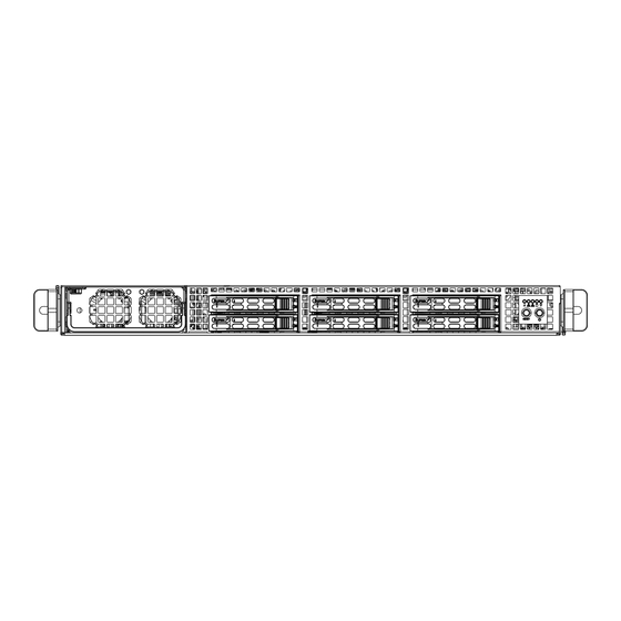
Page 78: Control Panel
A+ Server 1122GG-TF User's Manual Figure 6-1. Chassis: Front and Rear Views Power Supply Control Panel Hot-Swap Drive Bays (6) PCI Slot Dedicated IPMI LAN Port COM Port USB Ports LAN Ports VGA Port Control Panel The control panel (located on the front of the chassis) must be connected to the JF1 connector on the serverboard to provide you with system status indications. -
Page 79: Hard Drive Installation
Chapter 6: Advanced Chassis Setup Hard Drive Installation The hard drives are mounted in drive carriers to simplify their installation and re- moval from the chassis. These carriers also help promote proper airflow for the drive bays. For this reason, even empty carriers without drives installed must remain in the chassis during standard operation. - Page 80 A+ Server 1122GG-TF User's Manual Installing a Hard Drive into a Drive Carrier 1. Remove the dummy drive, which comes pre-installed in the drive carrier, by removing the screws securing the dummy drive to the carrier. Note that these screws cannot be reused on the actual 2.5" hard drive.
- Page 81 Chapter 6: Advanced Chassis Setup Installing a Hard Drive Carrier Into the Chassis 1. Insert the drive carrier into its bay, keeping the carrier oriented so that the hard drive is on the top of the carrier and the release button is on the right side. When the carrier reaches the rear of the bay, the release handle will retract.
-
Page 82: Peripheral Drive Installation
A+ Server 1122GG-TF User's Manual Peripheral Drive Installation Installing or Replacing a Peripheral Drive 1. Unplug the main power cords to the chassis. 2. Unplug the power and data cables from the motherboard and/or backplane to any drive you are replacing. -
Page 83: Installing The Air Shroud
Chapter 6: Advanced Chassis Setup Installing the Air Shroud Air shrouds concentrate airflow to maximize fan efficiency. The SC118G chassis air shroud does not require screws to set up Note: When installilng two GPU cards, the MCP-310-81803-0B air shroud must be used. -
Page 84: Checking The Air Flow
Installing Expansion Cards The SC118G chassis includes I/O slots for four full-height, full-length expansion cards, although the 1122GG-TF server supports only two. Alternatively, the server can be configured for two double-width, high-end graphics processor units (GPUs). In addition the chassis and serverboard support one low-profile expansion card Figure 6-6. -
Page 85: Installing An Expansion Card On The Left Side
Chapter 6: Advanced Chassis Setup Installing an Expansion Card on the Left Side On the left side (looking from the front) of the chassis, you can install a full-height, full-width expansion card, or a double width high-end graphics processing unit (GPU). -
Page 86: Installing An Expansion Card In The Center
A+ Server 1122GG-TF User's Manual Figure 6-8. Left Riser Card Bracket Installing a Low-Profile Card Screwdriver Icon Installing an Expansion Card in the Center Installing a Low Profile Expansion Card 1. Power down the system and remove the chassis cover. -
Page 87: Installing An Expansion Card On The Right Side
Chapter 6: Advanced Chassis Setup Installing an Expansion Card on the Right Side On the right side (looking from the front) of the chassis, you can install a full- height, full-width expansion card, or a double width high-end graphics processing unit (GPU). - Page 88 A+ Server 1122GG-TF User's Manual Figure 6-10. GPU Cards in the Chassis Note: Installing the optional graphics card configuration may require the I/O plate to be modified by cutting off any portion of the plate that may extend over the I/O panel components beside it.
-
Page 89: System Fans
Chapter 6: Advanced Chassis Setup System Fans Eight heavy-duty fans provide cooling for the chassis. These fans circulate air through the chassis as a means of lowering the chassis' internal temperature. The chassis includes counter-rotating fans. Each fan unit is actually made up of two fans joined back-to-back, which rotate in opposite directions. -
Page 90: System Fan Failure
A+ Server 1122GG-TF User's Manual System Fan Failure Fan speed is controlled by system temperature by means of a BIOS setting. If a fan fails, the remaining fans will ramp up to full speed. The system can continue to run with a failed fan. Replace any failed fan at your earliest convenience with the same type and model. -
Page 91: Power Supply
Chapter 6: Advanced Chassis Setup Power Supply The SC118G chassis includes a 1400 Watt power supply. This power supply is auto-switching capable. The power supply automatically sense and operates at a 100v to 240v input voltage. Power Supply Replacement If the power supply unit fails, the system will shut down and you will need to replace the unit. - Page 92 A+ Server 1122GG-TF User's Manual Notes 6-16...
-
Page 93: Chapter 7 Bios
Chapter 7: BIOS Chapter 7 BIOS Introduction This chapter describes the AMIBIOS™ Setup utility for the H8DGG-QF serverboard. The 16 Mb AMI BIOS® is stored in a flash chip and can be easily upgraded using a floppy disk-based program. Note: Due to periodic changes to the BIOS, some settings may have been added or deleted and might not yet be recorded in this manual. -
Page 94: Main Menu
A+ Server 1122GG-TF User's Manual Main Menu When you first enter AMI BIOS Setup Utility, you will see the Main Menu screen. You can always return to the Main Menu by selecting the Main tab on the top of the screen with the arrow keys. - Page 95 Chapter 7: BIOS Wait for F1 if Error This setting controls the system response when an error is detected during the boot sequence. When enabled, BIOS will stop the boot sequence when an error is detected, at which point you will need to press the F1 button to re-enter the BIOS setup menu.
- Page 96 A+ Server 1122GG-TF User's Manual Microcode Update This setting Enables or Disables microcode updating. Power Now This setting is used to Enable or Disable the AMD Power Now feature. ACPI SRAT Table This option Enables or Disables the building of the ACPI SRAT Table.
- Page 97 Chapter 7: BIOS Power Down Mode This sets the DDR power down mode. Options are Auto, Channel and Chip Select. DRAM Parity Enable This sets the DRAM Parity Enable to either Auto, Enabled and Disabled. Bank Swizzle Mode This sets the Bank Swizzle Mode to either Auto, Enabled and Disabled. ...
- Page 98 A+ Server 1122GG-TF User's Manual L2 Cache BG Scrub Allows L2 cache RAM to be corrected when idle. Options are Disabled and various times in nanoseconds and microseconds. L3 Cache BG Scrub Allows L3 cache RAM to be corrected when idle. Options are Disabled and various times in nanoseconds and microseconds.
- Page 99 Chapter 7: BIOS PATA Channel Configuration This allows you to set PATA channel configuration. Options include SATA as Primary or SATA as secondary. Power Saving Features Use this option to Enable or Disable power down saving features in the Southbridge chipset. This feature should be enabled for mobile systems and disabled for desktop systems.
- Page 100 A+ Server 1122GG-TF User's Manual Remap Port Device Number This setting allows you remap the Port Device number. Options include Auto and port numbers between 2 and 13. L1 Immediate ACK This setting allows you to Enable or Disable L1 ACK. When enabled, the L1 will be ACK'd immediately.
- Page 101 Chapter 7: BIOS Powerdown Unused Lanes This setting allows you to Enable or Disable the powerdown of unused lanes. Turnoff Off PLL During L1/L23 This setting allows you to Enable or Disable turning off PLL during L1/L23. TX Drive Strength Use this setting to configure TX drive strength.
- Page 102 A+ Server 1122GG-TF User's Manual Hyper Transport Configuration HT Extended Address This setting allows you to Enable or Disable the HT extended address. Op- tions include Enabled, Disabled and Auto. HT3 Link Power State This setting allows you to configure the HT3 Link power state. Options include Auto, LS0, LS1, LS2 and LS3.
- Page 103 Chapter 7: BIOS USB 2.0 Controller Mode Use this setting to configure the USB 2.0 Controller in either Hi-Speed (480 Mps) or Full Speed (12 Mps) mode. BIOS EHCI Hand Off This is a workaround for OS's without EHCI hand-off support. The EHCI ownership change should be claimed by the EHCI driver.
- Page 104 A+ Server 1122GG-TF User's Manual Block (Multi-Sector Transfer) Block mode boosts IDE drive performance by increasing the amount of data transferred. Only 512 bytes of data can be transferred per interrupt if block mode is not used. Block mode allows transfers of up to 64 KB per interrupt.
- Page 105 Chapter 7: BIOS disk drive support. Select "Disabled" to prevent AMI BIOS from using the S.M.A.R.T. Select "Enabled" to allow AMI BIOS to use the S.M.A.R.T. to sup- port hard drive disk. The options are Disabled, Enabled, and Auto. 32-Bit Data Transfer Select "Enabled"...
- Page 106 A+ Server 1122GG-TF User's Manual Pallette Snooping This option Enables or Disables Pallette Snooping. If enabled, the system informs the PCI devices that an ISA graphics device is installed in the sytem so the card will function normally. PCI IDE Busmaster Use this setting to Enable or Disable BIOS enabled uses of PCI Busmastering for reading or writing to IDE drives.
- Page 107 Chapter 7: BIOS Hotplug Reserve PFMemory Size This option sets the size of the memory block that is reserved for HotPlug or CardBus devices. Options include Auto, 32M, 64M, 128MB, 256MB, 512MB, 1024M and 2048M. SuperI/O Configuration Serial 1 Address This option specifies the base I/O port address and Interrupt Request address of serial port 1.
- Page 108 A+ Server 1122GG-TF User's Manual Flow Control Selects the flow control to be used for console redirection. Options are None, Hardware and Software. Redirection After BIOS POST This option sets redirction after BIOS POST. Options are Disable (no redirection after BIOS POST), Boot Loader (redirection during POST and during boot loader) and Always (redirection always active).
- Page 109 Chapter 7: BIOS CPU Temperature Display (CTD) CPU Temperature descriptions are defined as: Low [Tctl Value = Lowest Value, Tctl Value = -45] Medium [Tctl Value = -46, Tctl Value = 60] High [Tctl Value = -61 and Above] Note: Only CPU temperature (Low, Medium, High) and system temperature (RT1) are required to be displayed in BIOS and in-system monitoring software.
- Page 110 A+ Server 1122GG-TF User's Manual When COA (either Early or Default Alarm) is disabled, the following actions are required to be executed: • System overheating LED is required to be OFF. • Onboard buzzer or speaker is required to be OFF.
- Page 111 Chapter 7: BIOS IPMI Configuration This menu shows static information about the IPMI firmware revision and status of the BMC, as well as options for IPMI configuration. View BMC System Event Log Pressing the Enter key will open the following settings. Use the "+" and "-" keys to navigate through the system event log.
-
Page 112: Security Menu
A+ Server 1122GG-TF User's Manual Event Log Configuration View Event Log Pressing the Enter key will open the event log. Use the "h" and "i" keys to navigate through the system event log. Mark all Events as Read Selecting this and pressing the Enter key marks all events as read in the event log. -
Page 113: Boot Settings Menu
Chapter 7: BIOS Boot Settings Menu Boot Device Priority This feature allows you to prioritize the boot sequence from the list of available devices. A device that is in parenthesis has been disabled in the corresponding type menu. Hard Disk Drives This feature allows you to specify the boot sequence from the list of available hard disk drives. -
Page 114: Exit Menu
A+ Server 1122GG-TF User's Manual Exit Menu Select the Exit tab from AMI BIOS Setup Utility screen to enter the Exit BIOS Setup screen. Save Changes and Exit When you have completed the system configuration changes, select this option to leave BIOS Setup and reboot the computer, so the new system configuration parameters can take effect. -
Page 115: Appendix A Bios Error Beep Codes
Appendix A: BIOS Error Beep Codes Appendix A BIOS Error Beep Codes During the POST (Power-On Self-Test) routines, which are performed each time the system is powered on, errors may occur. Non-fatal errors are those which, in most cases, allow the system to continue the boot-up process. - Page 116 A+ Server 1122GG-TF User's Manual Notes...
-
Page 117: Appendix B Installing Windows
Appendix B: Installing Windows Appendix B Installing Windows After all hardware components have been installed, you must first configure RAID Settings before you install the Windows OS and other software drivers. To configure RAID settings, please refer to RAID Configuration User Guides posted on our web site at www.supermicro.com/support/manuals. -
Page 118: B-2 Installing Windows To A Non-Raid System
A+ Server 1122GG-TF User's Manual 9. From the Windows XP/Windows 2003 Setup screen, press the <Enter> key. The XP/2003 Setup will automatically load all device files and then, continue the Windows XP/Windows 2003 installation. 10. After the Windows XP/Windows 2003 OS Installation has completed, the system will automatically reboot. -
Page 119: Appendix C System Specifications
Appendix C: System Specifications Appendix C System Specifications Processors Dual AMD Opteron 6000 series (AMD Socket G34 type) processors Note: please refer to our website for details on supported processors. Chipset Dual AMD SR5690 chipsets and one SP5100 Southbridge chipset BIOS 16 Mb AMIBIOS SPI Flash ROM Memory Capacity... - Page 120 A+ Server 1122GG-TF User's Manual Chassis SC118GTS-1400BP (1U rackmount) Dimensions: (WxHxD) 17.2 x 1.7 x 28.2 in. (437 x 43 x 716 mm) Weight Gross (Bare Bone): 38 lbs. (17.2 kg) System Cooling Four sets of 4-cm counter-rotating cooling fans (fan speed controlled by BIOS...
- Page 121 Appendix C: System Specifications Notes...
- Page 122 A+ Server 1122GG-TF User's Manual (continued from front) The products sold by Supermicro are not intended for and will not be used in life support systems, medical equipment, nuclear facilities or systems, aircraft, aircraft devices, aircraft/emergency communication devices or other critical systems whose failure to perform be reasonably expected to result in significant injury or loss of life or catastrophic property damage.
Need help?
Do you have a question about the 1122GG-TF and is the answer not in the manual?
Questions and answers