Table of Contents
Advertisement
Quick Links
Advertisement
Table of Contents

Related Manuals for Norac UC 4.5 Hagie STS10


Summary of Contents for Norac UC 4.5 Hagie STS10
- Page 1 Hagie STS10 & 12 2000-2004 Installation Manual...
- Page 2 Reorder P/N: UC4.5-BC-HG1-INST Rev A (Hagie STS10 &12 2000-2004) NOTICE: NORAC Systems International Inc. reserves the right to improve products and their specifications without notice and without the requirement to update products sold previously. Every effort has been made to ensure the accuracy of the information...
-
Page 3: Table Of Contents
Contents Introduction ........................ 1 General UC4.5 System Layout ................. 2 Kit Parts ........................3 Ultrasonic Sensor Installation .................. 7 Roll Sensor Installation .................... 11 Electrical Installation ....................14 Hydraulic Installation .................... -
Page 4: Introduction
1 Introduction Congratulations on your purchase of the NORAC UC4.5 Spray Height Control System. This system is manufactured with top quality components and is engineered using the latest technology to provide operating reliability unmatched for years to come. When properly used the system can provide protection from sprayer boom damage, improve sprayer efficiency, and ensure chemicals are applied correctly. -
Page 5: General Uc4.5 System Layout
2 General UC4.5 System Layout Figure 1 illustrates the general layout of the UC4.5 system components: Figure 1: General UC4.5 System Layout... -
Page 6: Kit Parts
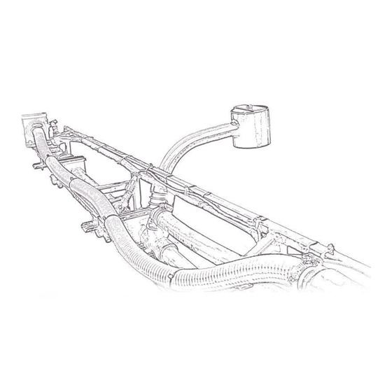
3 Kit Parts Kit Overview Figure 2: HG1 System Parts... - Page 7 Hydraulic Plumbing Figure 3: HG1 Hydraulic Plumbing...
- Page 8 UC5 NETWORK 6 PIN PLUG 44963D VALVE BLOCK ASSEMBLY 2 STATION CC/LS PROP DT 4 BOLT Optional Main Lift Kit An optional main lift sensor kit is available for purchase from NORAC. Part Number Name 4570BC UC4.5 MAIN LIFT OPTION - 44743...
- Page 9 SIZE FACE P - PIPE The use of dielectric grease is not recommended on any NORAC electrical connections. To ensure all stainless steel hardware does not gall or seize apply a light coating of the supplied Permatex Anti-seize grease (M06) to all threaded parts upon installation.
-
Page 10: Ultrasonic Sensor Installation
4 Ultrasonic Sensor Installation Bracket Assembly Assemble the breakaway sensor bracket as illustrated in Figure 4, following the instructions below. Figure 4: Breakaway Bracket Assembly 1. Compress the spring and insert it together with the collar into the base. 2. Slide the tube through the assembled part. 3. - Page 11 Ultrasonic Sensor Serial Number Arrangement When installing the sensors, start with the smallest serial number on the left-hand side, and proceed to the largest serial number on the right hand side. Each sensor has a serial number stamped on the sensor housing. Apply a light coating of the supplied Permatex Anti-seize grease (M06) to all threaded parts upon installation.
- Page 12 Ultrasonic Sensor Mounting Guidelines The following guidelines will ensure optimal sensor performance and prevent sensor measurement error. These rules should be followed for both the wing sensors and the main lift (middle) sensor. 1. In its lowest position, the sensor must be 9 inches (23 cm) or more from the ground (A). 2.
- Page 13 If the sensor is mounted to this portion of the boom, the system will force the boom downwards towards the ground as the boom folds backwards. 4. Mount the NORAC ultrasonic sensor into the sensor bracket and run the sensor cable through the sensor tube.
-
Page 14: Roll Sensor Installation
5 Roll Sensor Installation Bracket Assembly 1. To mount the roll sensors, the roll sensor brackets will have to be bent. The brackets are supplied with a 90° bend and must be bent back to a 45° bend. 2. Securely mount the roll sensors to the included roll sensor brackets using the #6 machine screws. - Page 15 Roll Sensor Mounting Guidelines: Front Mounted Rigid Booms 1. When mounting the roll sensors, mount the roll sensor with the temperature probe on the boom and the roll sensor without the temperature probe on the chassis near the sprayer cab. Figure 10: Roll Sensor Mounting on a Trapeze Suspended Boom 2.
- Page 16 Temperature Probe Once the block is mounted, fasten the temperature probe from E03 to the NORAC valve block using the included 3/8x1/2” bolt as illustrated in Figure 12. Figure 12: NORAC Valve Block with Temperature Probe Installed...
-
Page 17: Electrical Installation
6 Electrical Installation 1. Install the UC4.5 Control Panel (E01) in the cab of the sprayer. Mount the panel where it will be clearly visible and within easy reach of the operator. Figure 13: Cable Configurations: C01, C06 and C10 2. - Page 18 8. Connect the valve cable (C03) to C04. Connect the 2-pin connectors on C03 to the NORAC valve block, as shown in Figure 14. 9. The connectors on the valve cable (C03) are marked RIGHT UP, LEFT UP, RIGHT DOWN and LEFT DOWN.
-
Page 19: Hydraulic Installation
Valve Assembly 1. On a clean surface remove the plastic plugs from the block. 2. Install two 6MB-6MJ (F05) fittings on the “P” and “T” ports on the NORAC block. Tighten to 18 ft-lbs (24 Nm). 3. Insert the two orifices (F08) into the “B” ports with the notch facing out. - Page 20 1. A suitable mounting location for the valve block is illustrated in Figure 16. 2. Bolt the NORAC valve block to the mounting bracket (B12). 3. Remove the two bolts holding the Hagie valve block in place on the right side of the center rack.
- Page 21 1. After the NORAC valves are mounted, the hydraulic hoses and fittings can be plumbed. The plumbing for the hydraulic circuit is shown schematically in Figure 3. 2. Connect hoses from the NORAC “P” and “T” ports to the “P” and “T” ports on the sprayer valve block using fittings F03.
-
Page 22: Software Setup
8 Software Setup 1. Start up the sprayer and test the sprayer’s functionality. The NORAC control panel does not need to be powered on for the original boom function switches to operate. Unfold the booms and raise/lower each boom and the main section. -
Page 23: Cable Drawings
9 Cable Drawings ITEM C01: 44653-10 - CABLE UC4.5 ADAPTER MOLEX TO DEUTSCH 9.2 ITEM C03: 44656D – CABLE VALVE VARIABLE RATE DT... - Page 24 ITEM C04: 44651 - CABLE VALVE EXTENSION ITEM C05: 43210-20 - CABLE UC5 NETWORK 18 AWG - 20M...
- Page 25 ITEM C06: 43210-10 - CABLE UC5 NETWORK 18 AWG - 10M...
- Page 26 ITEM C08: 43220-03 - CABLE UC5 NETWORK 14 AWG - 3M...
- Page 27 ITEM C10: 44650-55 - CABLE UC4.5 POWER HAGIE STS12...
- Page 28 Canada NORAC Systems International Inc. Phone: (+1) 306 664 6711 Toll Free: 1 800 667 3921 Shipping Address: 3702 Kinnear Place Saskatoon, SK S7P 0A6 United States NORAC, Inc. Phone: (+1) 952 224 4142 Toll Free: 1 866 306 6722...
Need help?
Do you have a question about the UC 4.5 Hagie STS10 and is the answer not in the manual?
Questions and answers