Advertisement
Quick Links
Note: Room must be installed on flat, level surface.
710-0128 IG-840-SH / S840-H 4 Person IR Sauna
Ver. 2
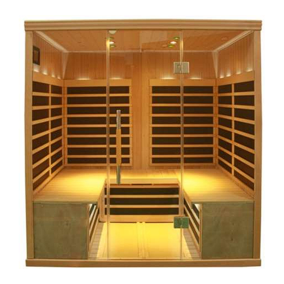
4 Person Infrared Sauna
IG-840-SH/S840
User Manual
This Product is covered by:
US Patents No. 8,692,168
Canadian Patents No. 2,729,500
2,794,059 & 2,813,340
and other Patents Pending.
Precautions Before Use
Preassembly Information
Electrical Requirements
Sauna Assembly
Electrical Connection-Under Bench
Electrical Connection-Inside Ceiling
Control Panel Instructions
Lighting Operation
Audio System
How to Use Sauna
Tips & Troubleshooting
Wiring Diagram
Warranty
S-Series
Page 1
2
2
3
4
11
14
17
18
18
20
21
22
23
11/3/14
Rev. 2
Advertisement

Related Manuals for Saunatec S Series


Summary of Contents for Saunatec S Series
- Page 1 S-Series 4 Person Infrared Sauna IG-840-SH/S840 User Manual This Product is covered by: US Patents No. 8,692,168 Canadian Patents No. 2,729,500 2,794,059 & 2,813,340 and other Patents Pending. Note: Room must be installed on flat, level surface. Precautions Before Use Preassembly Information Electrical Requirements Sauna Assembly...
-
Page 2: Precautions Before Use
Precautions before Use: Warning (Room Configuration & Use): Proper Electrical Grounding is Required Electrical Receptacles not Allowed in the Room Do not Apply Water to any Heating Element Do not Add a Locking or Latching System to the Door ... - Page 3 Electrical Requirements: The IR Sauna Room is designed for a 120 Volt AC / 15 or 20 Amp Circuit Breaker! A 120 Volt AC (dedicated) circuit is recommended to avoid unnecessary tripping of the breaker. The Sauna should be plugged into a NEMA (5-15R or 5-20R) Amp electrical outlet.
- Page 4 Sauna Assembly Instructions _________________________________________________________________________ Floor Panel (Box #1): Locate the Floor Panel on a level surface (3-6) inches from wall and no more than (5 ft) from 120 Volt AC / 20 amp dedicated receptacle. Position the Floor panel so that the Ceramic tiles / IR Floor Heaters are to the front of the room Note: place the Ceiling, Bench Skirt and Bench to the side until the appropriate steps.
- Page 5 Left Wall (Box #2): Place Left Wall panel into the left slot of the Floor Panel. Left Wall panel must be held in place until the Left Back Wall panel is added. Left Back Wall (Box #4): Place Left Back Wall section into the back slot of the Floor Panel. ...
- Page 6 Right Back Wall (Box #4): Place the Right Back Wall into the back slot of the Floor Panel. Interlock the Left and Right Back Wall Panels by lifting and hooking the interlocking brackets between them. Right Wall (Box #2): ...
- Page 7 Note: When wall panels are connected in place properly the corners will be flat on top. If one panel sits up higher than another, the panel is not locked in place properly or there is something under the panel. Ceiling (Box #1): ...
- Page 8 Once the Ceiling panel is lined up directly above the Wall panels; insert the wires harnesses from the wall panels into the holes in the Ceiling panel. Note: Position the cam locks on the top of the Left & Right Wall panels as shown above. ...
- Page 9 Front Wall (Box #2): Place the Right Side Front / Door panel into the Floor panel slot. Note: Do not let go of glass panel, it needs to be held in place. Slightly open the door, while one person supports the glass panel. This will give access to put in the Left Side Light.
- Page 10 Bench Skirt (Box #1): Insert the Bench Skirt in between the back Wall and the Left Wall wing panel tracks. Slide Bench Skirts all the way to the floor. Do not pinch any wires under the skirt. Bench Top (Box #1): ...
- Page 11 Electrical Connections (under bench - right side): Connect wire #4 from the left distribution plate to #4 from Back Wall harness. Connect wire #5 from the left distribution plate to #5 from the Back Wall harness. Connect wire #6 from the left distribution plate to the Back Wall harness wire #6. ...
- Page 12 Electrical Connections (under bench - left side): Connect wire L2 from the left distribution plate to L2 from the Left Wall panel. Connect wire B1 from the left distribution plate to B1 from the Back Wall panel. Connect L1 from the right distribution plate to L1 from Left Wall panel.
- Page 13 Bench tops can now be fit into place. Bench must tuck under the back heater guard and then push all the way to the wall. The Bench Top should fit down flush from front to back. It may be necessary to use the openings in the skirt to apply pressure forward or rearward on the skirt to allow the bench to drop into place.
- Page 14 Electrical Connections (inside the Ceiling panel-back right corner): Open all hatch doors on the ceiling to locate the necessary electrical plugs. Access the connectors and connect them according to the labels on the harness. Connect wire #4 from the Back Wall harness to the Ceiling wire #4. ...
- Page 15 Electrical Connections (inside the Ceiling-Right front corner): Refer to picture below; remove the radio antenna from the Ceiling hatch by pulling out wire. Spread blue antenna wires and lay across the roof of the sauna. Sauna Room 120 Volt AC Power Cord: ...
- Page 16 Deluxe Door Handles: Your sauna comes equipped with a deluxe door handle. Locate brown box (typically in the floor/ceiling carton) Step 1. Separate two pieces by loosening four set screws with Allen wrench provided. Step 2. Remove bolts and spacer from first handle piece. You will need a Phillips Screw driver.
- Page 17 The Sauna Rooms is now ready to use! ------------------------------------------------------------------------------------------------------------------------------------------------ Control Panel Instructions: Power Delay Actual Timer Timer Button Temperature Temperature Audio Valance/ Color Floor Bench Bench On/Off Reading Therapy Skirt Heat Heat Lights On/Off On/Off On/Off On/Off Main Power: Press POWER button in the upper middle portion of the screen. When lit red, control is ON. When white, control is OFF.
- Page 18 Light Functions: 1. Press “Valance/Reading button” to turn ON or OFF 2. Note: “Outside Light” ON or OFF will not be functional on “S” series models. Color Therapy Functions: Press “Color Therapy Light” to activate a color light or sequence. The following details this sequence: press –...
- Page 19 “Mode” allows you to switch between the FM radio and other audio devices that may be plugged in to the controller. “Band” Changes the selection of radio channels. To search for only close range high signal local stations, choose LV H, mid-range LV M and long range LV L. Searching for radio stations or advancing audio files can be done with the arrows in the lower right hand corner of the screen.
- Page 20 How to Use Infrared Sauna: Avoid eating large meals and excessive alcohol intake before using Sauna. Never smoke or drink alcohol or exercise inside of Sauna. If you are taking any medications or under the care of a Physician, consult with them prior to Sauna usage. Refer to Sauna Usage Warning signs located inside of Sauna Room Prior to Sauna session, if possible before using Sauna, take a warm shower without drying.
-
Page 21: Troubleshooting Tips
Ensure the floor is flat by using a level on the ceiling of the room. It may be necessary to use a small door or window shim to adjust the level under the floor. ------------------------------------------------------------------------------------------- For additional assistance or service questions? Please do not hesitate contacting Saunatec/TyloHelo Mon – Fri. 8AM – 5PM CST 1-888-780-4427 techsupport@tyloheloinc.com... - Page 22 710-0128 IG-840-SH / S840-H 4 Person IR Sauna Page 22 11/3/14 Ver. 2 Rev. 2...
- Page 23 710-0128 IG-840-SH / S840-H 4 Person IR Sauna Page 23 11/3/14 Ver. 2 Rev. 2...
Need help?
Do you have a question about the S Series and is the answer not in the manual?
Questions and answers