Table of Contents
Advertisement
Quick Links
Note: Room must be installed on flat, level surface.
710-0130 IG-880-SH / S880-H 3-4 Person IR Sauna
Ver. 3
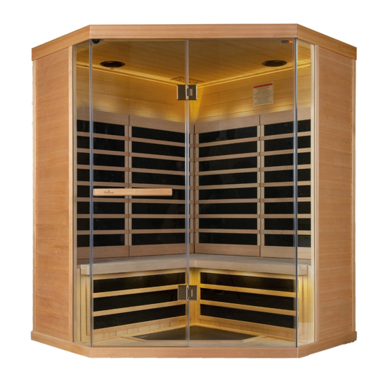
3-4 Person Infrared Sauna
Touch Pad and Bluetooth
IG-880-SH/S880 User Manual
This Product is covered by:
US Patents No. 8,692,168
Canadian Patents No. 2,729,500
2,794,059 & 2,813,340
and other Patents Pending.
S3-Series
Page 1
2
2
3
4
7
12
14
14
15
16
17
18
19
04/09/19
Rev. 4
Advertisement
Table of Contents

Related Manuals for Saunatec S3-880


Summary of Contents for Saunatec S3-880
-
Page 1: Table Of Contents
S3-Series 3-4 Person Infrared Sauna Touch Pad and Bluetooth IG-880-SH/S880 User Manual This Product is covered by: US Patents No. 8,692,168 Canadian Patents No. 2,729,500 2,794,059 & 2,813,340 and other Patents Pending. Note: Room must be installed on flat, level surface. Precautions Before Use Preassembly Information Electrical Requirements... -
Page 2: Precautions Before Use
Precautions before Use: Warning (Room Configuration & Use): Proper Electrical Grounding is Required Electrical Receptacles not Allowed in the Room Do not Apply Water to any Heating Element Do not Add a Locking or Latching System to the Door ... -
Page 3: Electrical Requirements
Electrical Requirements: The IR Sauna Room is designed for a 120 Volt AC / 15 or 20 Amp Circuit Breaker! A 120 Volt AC (dedicated) circuit is recommended to avoid unnecessary tripping of the breaker. The Sauna should be plugged into a NEMA (5-15R or 5-20R) Amp electrical outlet. -
Page 4: Sauna Assembly
Sauna Assembly Instructions _________________________________________________________________________ Floor Panel (Box #1): Locate the Floor Panel on a level surface (3-6) inches from wall and no more than (5 ft) from 120 Volt AC / 15 amp dedicated receptacle. Position the Floor panel so that the Ceramic tiles / IR Floor Heaters are to the front of the room Note: place the Ceiling, Bench Skirt and Bench to the side until the appropriate steps. - Page 5 Right Back Wall (Box #3): Place Back Right Wall panel into the back slot of the Floor Panel. Back Right Wall panel must be held in place until the Back Left Wall panel is added. Left Back Wall (Box #2): ...
- Page 6 Left & Right Front Wood Walls (Box #3): Place Left Front Wall section into the left slot of the Floor Panel. Attach the Left Back Wall to the Left Front Wall by lifting up the Wall slid into the Left Front corner interlock brackets.
-
Page 7: Electrical Connection-Under Bench
Bench Top (Box #1): Slide the Long Bench seat down against the back wall with Power Junction Box facing you. Tilt the Bench against the Back Wall so it will remain standing. Electrical Connections (under bench - left side): ... - Page 8 Electrical Connections (under bench - right side): Connect wire #4 from distribution plate to #4 from Back Wall harness. Connect wire #5 from the distribution plate to #5 from the Back Wall harness. Connect wire #6 from the Back Wall harness to the distribution plate wire #6. ...
- Page 9 Locate the electrical switch on the black Master Control Box and ensure the switch is on. Bench Top (Right Side): Install the Right Bench Top by tucking the back of the bench under the heater guard. Push Bench Top all the way to the Right Back Wall. ...
- Page 10 Left & Right Glass Sidelights (Box #2): Place the Front Left Sidelight panel into the Floor panel slot and the adjacent Left Wall panel slot. Place the Front Right Sidelight panel into the Floor panel slot and the adjacent Right Wall panel slot.
- Page 11 Once the Ceiling panel is lined up directly above the Wall panels; insert the wires harnesses from the wall panels into the holes in the Ceiling panel. Note: Position the cam locks on the top of the Left & Right Wall panels as shown above. Front Wall Glass (Box #2): ...
-
Page 12: Electrical Connection-Inside Ceiling
Electrical Connections (inside the Ceiling panel-rear right): Open all hatch doors on the ceiling to locate the necessary electrical plugs. Access the connectors and connect them according to the labels on the harness. Connect wire #4 from the Back Wall harness to the Ceiling wire #4. ... - Page 13 Electrical Connections (inside the Ceiling panel-back corner & middle-not pictured): Connect Wall panel wire #7 to Ceiling wire #7. Sauna Room 120 Volt AC Power Cord: Plug the Sauna room power cord into the 20 amp / 5-20R wall receptacle as noted in page 3 Note: It is important that the sauna be plugged into a dedicated outlet of the correct rating.
-
Page 14: Control Panel Instructions
Control Panel Instructions: Color Therapy Bench Heat Lights Interior Lights Valance Power ON or Light Main Power: Press POWER to switch room ON or OFF Timer Functions: Press and hold “+” or “–“ to set room operating time. Increases time (5 minute increments) / Decreases time (5 minute increments) Temperature Functions: Press to alternate between either C or F (C or F will light to indicate the units desired) Press and hold + or –... -
Page 15: Audio System
Audio System: Audio Power ON or OFF Auxiliary Input AUDIO OPERATION Audio Power On Press Bluetooth icon to turn on or off audio system Blue LED indicates the audio system is operating. Bluetooth Bluetooth is always enabled when blue LED is glowing and Aux Input is not connected Auxiliary Input ... -
Page 16: How To Use Sauna
How to Use Infrared Sauna: Avoid eating large meals and excessive alcohol intake before using Sauna. Never smoke or drink alcohol or exercise inside of Sauna. If you are taking any medications or under the care of a Physician, consult with them prior to Sauna usage. Refer to Sauna Usage Warning signs located inside of Sauna Room Prior to Sauna session, if possible before using Sauna, take a warm shower without drying. -
Page 17: Tips & Troubleshooting
Ensure the floor is flat by using a level on the ceiling of the room. It may be necessary to use a small door or window shim to adjust the level under the floor. ------------------------------------------------------------------------------------------- For additional assistance or service questions? Please do not hesitate contacting Saunatec/TyloHelo Mon – Fri. 8AM – 5PM CST 1-888-780-4427 techsupport@tyloheloinc.com... -
Page 18: Wiring Diagram
710-0130 IG-880-SH / S880-H 3-4 Person IR Sauna Page 18 04/09/19 Ver. 3 Rev. 4... -
Page 19: Warranty
710-0130 IG-880-SH / S880-H 3-4 Person IR Sauna Page 19 04/09/19 Ver. 3 Rev. 4...
Need help?
Do you have a question about the S3-880 and is the answer not in the manual?
Questions and answers