Table of Contents
Advertisement
Quick Links
SERVICE & OPERATING MANUAL
Original Instructions
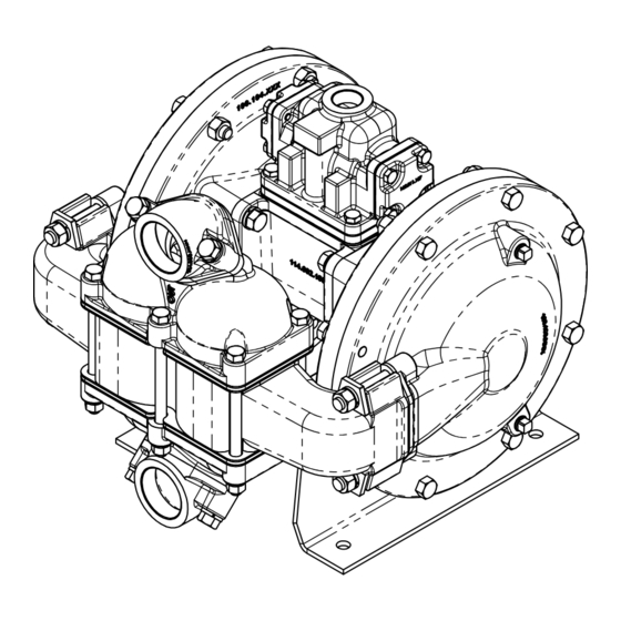
9.96 253
Certified Quality
2.23 57
.19 5
SUCTION PORT
ISO 9001 Certified
ISO 14001 Certified
1 1/2" NPT (1 1/2" BSP TAPERED)
9.00 229
Warren Rupp, Inc.
A Unit of IDEX Corporation
800 N. Main St.,
Mansfield, Ohio 44902 USA
Telephone (419) 524.8388
Fax (419) 522.7867
SANDPIPERPUMP.COM
©2017 Warren Rupp, Inc.
12.06 306
HDB1½ / HDB40
13.87 352
Heavy Duty Ball Valve
Design Level 8
*
1.18 30
AIR EXHAUST
3/4" NPT
4X
.47 12
MOUNTING HOLES
*
INDICATES DIMENSIONS WITH SUCTION
AND DISCHARGE PORTS ROTATED 180°
TO A VERTICAL POSITION
*
11.00 279
s a n d p i p e r p u m p. c o m
6.81 173
Advertisement
Table of Contents

Related Manuals for Warren rupp Sandpiper HDB1 1/2


Summary of Contents for Warren rupp Sandpiper HDB1 1/2
- Page 1 Mansfield, Ohio 44902 USA AND DISCHARGE PORTS ROTATED 180° Telephone (419) 524.8388 TO A VERTICAL POSITION Fax (419) 522.7867 SANDPIPERPUMP.COM ©2017 Warren Rupp, Inc. s a n d p i p e r p u m p. c o m...
-
Page 2: Safety Information
The use of non-OEM replacement parts will void (or negate) during reassembly. agency certifications, including CE, ATEX, CSA, 3A and EC1935 compliance (Food Contact Materials). Warren Rupp, Inc. cannot ensure nor warrant non-OEM parts to meet the stringent Use safe practices when lifting requirements of the certifying agencies. - Page 3 Temperature Tables Table 1. Category 1 & Category 2 ATEX Rated Pumps Ambient Temperature Process Temperature Temperature Maximum Surface Tem- Range [°C] Range [°C] Class perature [°C] -20°C to +80°C T100°C -20°C to +108°C T135°C -20°C to +60°C -20°C to + 160°C T200°C -20°C to +177°C (225°C) T2...
- Page 4 Table of Contents SECTION 1: PUMP SPECIFICATIONS ....1 • Explanation of Nomenclature • Performance • Materials • Dimensional Drawings SECTION 2: INSTALLATION & OPERATION ...5 • Principle of Pump Operation • Recommended Installation Guide • Troubleshooting Guide SECTION 3: EXPLODED VIEW ......8 •...
-
Page 5: Explanation Of Pump Nomenclature
I M1 Ex h I Ma II 2 G Ex h IIC T5...225°C (T2) Gb A, H, I, S, X A, I, S, Y, Z ATEX Details II 2 D Ex h IIIC T100°C...T200°C Db Explanation of Pump Nomenclature II 2 G Ex h ia IIC T5 Gb II 1 G Ex h IIC T5...225°C (T2 A, H, I, S, X A, I, S, Y, Z... - Page 6 Performance MODEL HDB1½ Performance Curve HDB1½/HDB40 AIR CONSUMPTION Performance based on the following: elastomer fitted pump, flooded suction, SCFM (M /hr) water at ambient conditions. The use of other materials and varying hydraulic SUCTION/DISCHARGE PORT SIZE conditions may result in deviations in excess of 5%. 10(17) •...
-
Page 7: Dimensional Drawings
Dimensional Drawings HDB1 1/2 & HDB40, Side Ported Dimensions are ± .13" (3mm). Figures in parenthesis = millimeters 14.84 9.15 DISCHARGE PORT 1 1/2" NPT [1 1/2" BSP TAPERED] AIR INLET 15.50 8.71 3/4" NPT 7.67 12.37 VERTICAL DISCHARGE 13.88 10.27 6.81 1.03... -
Page 8: Principle Of Pump Operation
Principle of Pump Operation Air-Operated Double Diaphragm (AODD) pumps are powered by compressed air or nitrogen. The main directional (air) control valve distributes ① compressed air to an air chamber, exerting uniform pressure over the inner surface of the diaphragm . - Page 9 Recommended Installation Guide Available Accessories: 1. Surge Suppressor Unregulated Air Supply to Surge 2. Filter/Regulator Suppressor 1 Surge Suppressor 3. Air Dryer 4. Lubricator Pressure Gauge Note: Surge Suppressor and Shut-Off Valve Piping, including air line, must be supported after the flexible connections.
-
Page 10: Troubleshooting Guide
Troubleshooting Guide Symptom: Potential Cause(s): Recommendation(s): Pump Cycles Once Deadhead (system pressure meets or exceeds air Increase the inlet air pressure to the pump. Pump is designed for 1:1 pressure ratio at zero flow. supply pressure). (Does not apply to high pressure 2:1 units). Air valve or intermediate gaskets installed incorrectly. - Page 11 ITEM PART N Composite Repair Parts Drawing - Side Ported 031.01 050.XX 070.00 095.07 114.00 115.XX 132.00 135.01 170.02 170.02 170.03 170.04 170.05 170.06 170.13 196.19 196.19 286.00 286.02 286.11 TORQUE: 360 IN-LBS 334.00 334.00 TORQUE: 480 IN-LBS 334.00 360.02 360.04 360.04 360.11...
-
Page 12: Composite Repair Parts List
Composite Repair Parts List Item Part Number Description Qty. 031.212.156 Air Valve Assy 334.008.010 Flange, Threaded (w/ cast iron wetted) (Aluminum Center - see pg #12 for details) 334.008.110 Flange, Threaded (w/ stainless wetted) 031.212.010 Air Valve Assy (Cast Iron Center) 334.008.156E Flange, Threaded (w/ aluminum wetted) BSP Threads 1 031.212.001... -
Page 13: Material Codes
656 ..Santoprene Diaphragm and ® end up in a landfill. The recyclability of SANDPIPER 360..Nitrile Rubber Color coded: RED Check Balls/EPDM Seats products is a vital part of Warren Rupp’s commitment 363..FKM (Fluorocarbon) 661..EPDM/Santoprene ® to environmental stewardship. Color coded: YELLOW 666..FDA Nitrile Diaphragm,... -
Page 14: Air Distribution Valve Assembly
Air Distribution Valve Assembly Air Distribution Valve Servicing See repair parts drawing, remove screws. Step 1: Remove Hex Head Cap Screws (1-G). Step 2: Remove end cap (1-F), gasket (1-E) and bumper (1-C). Step 3: Remove spool part of (1-B) (caution: do not scratch). Step 4: Press sleeve (1-B) from body (1-A). -
Page 15: Pilot Valve Assembly
Pilot Valve Assembly Pilot Valve Servicing PILOT VALVE ASSEMBLY PARTS LIST With Pilot Valve removed from pump. Item Part Number Description Step 1: Remove snap ring (4-F). 095.073.001 Pilot Valve Assembly Step 2: Remove sleeve (4-B), inspect O-Rings (4-C), 095.070.558 Valve Body 755.025.000 Sleeve (With O-Rings) -
Page 16: Diaphragm Servicing
Diaphragm Servicing Step 1: With manifolds and outer chambers Step 8: On opposite side of pump, thread the removed, remove diaphragm assemblies from remaining assembly onto the diaphragm rod. Using a diaphragm rod. DO NOT use a pipe wrench or similar torque wrench, tighten the assembly to the diaphragm tool to remove assembly from rod. -
Page 17: Declaration Of Conformity
Warren Rupp, Inc. (“Warren Rupp”) warrants to the original end-use purchaser that no product sold by Warren Rupp that bears a Warren Rupp brand shall fail under normal use and service due to a defect in material or workmanship within five years from the date of shipment from Warren Rupp’s factory. -
Page 18: Eu Declaration Of Conformity
A Unit of IDEX Corporation 800 North Main Street Mansfield, OH 44902 USA Warren Rupp, Inc. declares that Air Operated Double Diaphragm Pumps (AODD) and Surge Suppressors listed below comply with the requirements of Directive 2014/34/EU and all applicable standards. Applicable Standards •...
Need help?
Do you have a question about the Sandpiper HDB1 1/2 and is the answer not in the manual?
Questions and answers