Warren rupp Sandpiper Signature Series Service & Operating Manual
Heavy duty flap valve design level 2
Hide thumbs
Also See for Sandpiper Signature Series:
- Service & operating manual (19 pages) ,
- Service and operating manual (17 pages)
Advertisement
Quick Links
SERVICE & OPERATING MANUAL
Original Instructions
Certified Quality
ISO 9001 Certified
ISO 14001 Certified
Warren Rupp, Inc.
A Unit of IDEX Corporation
800 N. Main St.,
Mansfield, Ohio 44902 USA
Telephone (419) 524.8388
Fax (419) 522.7867
SANDPIPERPUMP.COM
© Copyright 2017 Warren Rupp, Inc.
All rights reserved
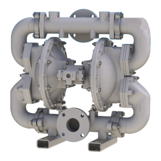
Model HDF3M
& HDF4M
Heavy Duty Flap Valve
Design Level 2
s a n d p i p e r p u m p. c o m
Advertisement

Subscribe to Our Youtube Channel
Related Manuals for Warren rupp Sandpiper Signature Series


Summary of Contents for Warren rupp Sandpiper Signature Series
- Page 1 800 N. Main St., Mansfield, Ohio 44902 USA Telephone (419) 524.8388 Fax (419) 522.7867 SANDPIPERPUMP.COM © Copyright 2017 Warren Rupp, Inc. All rights reserved s a n d p i p e r p u m p. c o m...
- Page 2 The use of non-OEM replacement parts will void (or negate) agency certifications, including CE, ATEX, CSA, 3A and EC1935 compliance (Food Contact Materials). Warren Rupp, Inc. cannot ensure nor warrant non-OEM parts to meet the stringent requirements of the certifying agencies.
- Page 3 Temperature Tables Table 1. Category 1 & Category 2 ATEX Rated Pumps Ambient Temperature Process Temperature Temperature Maximum Surface Tem- Range [°C] Range [°C] Class perature [°C] -20°C to +80°C T100°C -20°C to +108°C T135°C -20°C to +60°C -20°C to + 160°C T200°C -20°C to +177°C (225°C) T2...
- Page 4 Table of Contents SECTION 1: PUMP SPECIFICATIONS ....1 • Explanation of Nomenclature • Performance • Materials • Dimensional Drawings SECTION 2: INSTALLATION & OPERATION ...4 • Principle of Pump Operation • Recommended Installation Guide • Troubleshooting Guide SECTION 3: EXPLODED VIEW ......7 •...
- Page 5 Explanation of Pump Nomenclature HDF3A PB1/4 ATEX Details Construction Options ATEX Details Construction Options II 1 G Ex h IIC T5...225°C (T2) Ga II 2 G Ex h IIC T5...225°C (T2) Gb II 1D Ex h IIIC T100°C...T200°C Da II, SI II 2 D Ex h IIIC T100°C...T200°C Db Your Model #: _____...
- Page 6 Performance HDF3M/HDF4M SUCTION/DISCHARGE PORT SIZE MODEL HDF3M/HDF4M Performance Curve • HDF3-M: 3" ANSI 150# Style Flange Performance based on the following: elastomer fitted pump, flooded suction, water at ambient temperature. . • HDF4-M: 4" ANSI 150# Style Flange The use of other materials and varying hydraulic conditions may result in deviations in excess of 5%. AIR CONSUMPTION SCFM (M 3 /hr) CAPACITY...
- Page 7 Dimensional Drawings HDF3-M Heavy Duty Flap Valve Dimensions in inches (metric dimensions in brackets). Dimensional Tolerance .125" (3mm). 32.31 16.19 SUCTION PORT 7.50 3.75 AIR INLET 3" 150# ANSI 3/4" NPT (FEMALE) STYLE FLANGE 30.31 26.56 DISCHARGE PORT 3" 150# ANSI 15.93 STYLE FLANGE 5.06...
- Page 8 Dimensional Drawings HDF4-M Heavy Duty Flap Valve Dimensions in inches (metric dimensions in brackets). Dimensional Tolerance .125" (3mm). 32.31 16.19 9.00 AIR INLET 3/4" NPT (FEMALE) SUCTION PORT 4" 150# ANSI STYLE FLANGE 31.06 26.56 DISCHARGE PORT 4" 150# ANSI 15.93 15.93 STYLE FLANGE...
- Page 9 Principle of Pump Operation Air-Operated Double Diaphragm (AODD) pumps are powered by compressed The pump primes as a result of the suction stroke. The suction stroke lowers (P3) air or nitrogen. the chamber pressure increasing the chamber volume. This results in (P4) a pressure differential necessary for atmospheric pressure to push the...
- Page 10 Recommended Installation Guide Available Accessories: 1. Surge Suppressor 2. Filter/Regulator 3. Air Dryer 4. Lubricator Note: Surge Suppressor and Unregulated Air Piping, including air line, Supply to Surge must be supported after Suppressor the flexible connections. Pipe Connection Compound (Style Optional Gauge Shut-Off Flexible Connector...
- Page 11 Troubleshooting Guide Symptom: Potential Cause(s): Recommendation(s): Pump Cycles Once Deadhead (system pressure meets or exceeds air Increase the inlet air pressure to the pump. Pump is designed for 1:1 pressure ratio at zero flow. supply pressure). (Does not apply to high pressure 2:1 units). Air valve or intermediate gaskets installed incorrectly.
- Page 12 Composite Repair Parts Drawing ITEM NO. PART NUMBER 031.019.010 070.006.170 095.073.001 114.038.010 * USED ON HDF4-M ONLY 115.068.080 132.002.360 135.016.162 170.012.330 170.023.330 170.024.000 170.045.330 170.066.330 170.082.330 170.095.330 196.060.010 196.100.015 TORQUE: 600 IN-LBS. (67 N-m) 286.098.XXX 312.015.010 TORQUE: 600 IN-LBS. 312.016.010 (67 N-m) 326.004.080 334.020.000...
- Page 13 Composite Repair Parts List Item Part Number Description Item Part Number Description 031.019.010 Air Valve Assembly 570.010.365 Pad, Wear - Neoprene 070.006.170 Bushing, Intermediate 612.090.010 Plate, Outer Diaphragm (included in item #4) (includes item #48) 095.073.001 Pilot Valve Assy 612.124.010 Plate, Inner Diaphragm 114.002.010 Intermediate...
- Page 14 The recyclability of SANDPIPER 360..Nitrile Rubber Color coded: RED 656 ..Santoprene Diaphragm and ® products is a vital part of Warren Rupp’s commitment 363..FKM (Fluorocarbon) Check Balls/EPDM Seats to environmental stewardship. Color coded: YELLOW 661..EPDM/Santoprene ®...
- Page 15 Air Distribution Valve Assembly Air Distribution Valve Assembly Air Distribution Valve Servicing See repair parts drawing, remove screws. Step 1: Remove Hex Head Cap Screws (1-G). Step 2: Remove end cap (1-F), gasket (1-E) and bumper (1-C). Step 3: Remove spool part of (1-B) (caution: do not scratch). Step 4: Press sleeve (1-B) from body (1-A).
- Page 16 MODEL SPECIFIC Pilot Valve Assembly Pilot Valve Assembly Pilot Valve Assembly Pilot Valve Servicing PILOT VALVE ASSEMBLY PARTS LIST With Pilot Valve removed from pump. Item Part Number Description Step 1: Remove snap ring (3-F). 095.073.001 Pilot Valve Assembly Step 2: Remove sleeve (3-B), inspect O-Rings (3-C), 095.070.558 Valve Body 755.025.000...
- Page 17 Diaphragm Servicing Step 1: With manifolds and outer chambers Step 8: On opposite side of pump, thread the removed, remove diaphragm assemblies from remaining assembly onto the diaphragm rod. Using a diaphragm rod. DO NOT use a pipe wrench or similar torque wrench, tighten the assembly to the diaphragm tool to remove assembly from rod.
- Page 18 Warren Rupp, Inc. (“Warren Rupp”) warrants to the original end-use purchaser that no product sold by Warren Rupp that bears a Warren Rupp brand shall fail under normal use and service due to a defect in material or workmanship within five years from the date of shipment from Warren Rupp’s factory.
- Page 19 A Unit of IDEX Corporation 800 North Main Street Mansfield, OH 44902 USA Warren Rupp, Inc. declares that Air Operated Double Diaphragm Pumps (AODD) and Surge Suppressors listed below comply with the requirements of Directive 2014/34/EU and all applicable standards. Applicable Standards •...
Need help?
Do you have a question about the Sandpiper Signature Series and is the answer not in the manual?
Questions and answers