Table of Contents
Advertisement
Quick Links
SERVICE & OPERATING MANUAL
Original Instructions
Certified Quality
ISO 9001 Certified
ISO 14001 Certified
Certified to CSA Technical Letter No, R-14
Certified to ANSI LC6-2008
Warren Rupp, Inc.
A Unit of IDEX Corporation
800 N. Main St.,
Mansfield, Ohio 44902 USA
Telephone (419) 524.8388
Fax (419) 522.7867
SANDPIPERPUMP.COM
© Copyright 2017 Warren Rupp, Inc.
All rights reserved
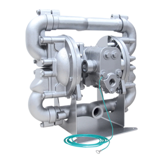
Model G10F
Metallic
Design Level 1
Natural Gas-Operated 1" Flap Valve
s a n d p i p e r p u m p. c o m
Advertisement
Table of Contents

Related Manuals for Warren rupp SANDPIPER G Series


Summary of Contents for Warren rupp SANDPIPER G Series
- Page 1 800 N. Main St., Mansfield, Ohio 44902 USA Telephone (419) 524.8388 Fax (419) 522.7867 SANDPIPERPUMP.COM © Copyright 2017 Warren Rupp, Inc. All rights reserved s a n d p i p e r p u m p. c o m...
- Page 2 The use of non-OEM replacement parts will void (or negate) agency certifications, including CE, ATEX, CSA, 3A and EC1935 compliance (Food Contact Materials). Warren Rupp, Inc. cannot ensure nor warrant non-OEM parts to meet the stringent Use safe practices when lifting requirements of the certifying agencies.
- Page 3 Temperature Table Table 1. Category 1 & Category 2 ATEX Rated Pumps Ambient Temperature Process Temperature Temperature Maximum Surface Tem- Range [°C] Range [°C] Class perature [°C] -20°C to +80°C T100°C -20°C to +108°C T135°C -20°C to +60°C -20°C to + 160°C T200°C -20°C to +177°C (225°C) T2 Per CSA standards ANSI LC6-2018 US & Canadian Technical Letter R14, G-Series Natural Gas Models are restricted to (-20°C to + 80°C) process temperature Table 2. Category 2 ATEX Rated Pumps Equipped with Pulse Output Kit or Integral Solenoid: Options Ambient Temperature Process Temperature...
-
Page 4: Table Of Contents
Table of Contents SECTION 1: PUMP SPECIFICATIONS ....1 • Explanation of Nomenclature • Performance • Materials • Dimensional Drawings SECTION 2: INSTALLATION & OPERATION ...4 • Principle of Pump Operation • Recommended Installation Guide • Troubleshooting Guide SECTION 3: EXPLODED VIEW ......7 •... -
Page 5: Explanation Of Nomenclature
Explanation of Pump Nomenclature Your Model #: ____ ____ (fill in from pump nameplate) Pump Pump Check Design Wetted Diaphragm/ Check Valve Non-Wetted Porting Pump Muffler Pump Brand Size Valve Level Material Check Valve Seat Material Options Style Options Options Model #: Pump Brand Non-Wetted Material Options... -
Page 6: Performance
Performance G10F MODEL G10F Performance Curve SUCTION/DISCHARGE PORT SIZE Performance based on the following: elastomer fitted pump, flooded suction, GAS CONSUMPTION 1” (25.4mm) NPT water at ambient temperature. Average displacement per pump stroke: .10 Gallons (.38 Liters). SCFM (M 3 /hr) The use of other materials and varying hydraulic conditions may result in deviations in excess of 5%. -
Page 7: Dimensional Drawings
Dimensional Drawings G10F Natural Gas Operated 1" Flap Valve Dimensions in inches (metric dimensions in brackets). Dimensional Tolerance .125" (3mm). SUCTION PORT 11.11 1" NPT OR 1" BSP TAPERED 16.73 6.11 2.38 (OPTIONAL 90 PORT ROTATION) GAS EXHAUST 3/4" NPT 15.59 16.41 14.03... -
Page 8: Principle Of Pump Operation
Principle of Pump Operation Gas-Operated Double Diaphragm pumps are powered by compressed gas, nitrogen or natural gas. The main directional (gas) control valve distributes ① compressed gas to an gas chamber, exerting uniform pressure over the inner surface of the diaphragm . -
Page 9: Recommended Installation Guide
Recommended Installation Guide 020.064.000 Filter VENTING WARNING: This filter is equipped with a stainless steel manual drain. The port is 1/8" NPT. When draining moisture from the filter, first shut off the natural gas supply. 020.058.000 REGULATOR WITH GAGE PRESSURE WARNING: This regulator is to be installed at point of use with the pump. The maximum gas supply is 400psi. Full line pressure needs to be regulated below 400psi prior to the regulator installation position. -
Page 10: Troubleshooting Guide
Troubleshooting Guide Symptom: Potential Cause(s): Recommendation(s): Pump Cycles Once Deadhead (system pressure meets or exceeds gas Increase the inlet gas pressure to the pump. Pump is designed for 1:1 pressure ratio at zero flow. supply pressure). (Does not apply to high pressure 2:1 units). Gas valve or intermediate gaskets installed incorrectly. -
Page 11: Composite Repair Parts Drawing
Composite Repair Parts Drawing Service & Repair Kits 476.361.363 Gas End Kit with FKM elastomer parts Sleeve and Spool Set, Pilot Valve Assembly, Bumpers, Bushings, Gaskets, O-rings, Seals, Plungers, and Retaining Rings 476.341.363 Gas End Wear Kit with FKM elastomer parts Bumpers, Bushings, Gaskets, O-rings, Seals, Plungers, and Retaining Rings 476.361.000... -
Page 12: Composite Repair Parts List
Composite Repair Parts List Item Part Number Description Item Part Number Description 031.203.000 Assembly, Air Valve 542.001.330 Nut, Square 031.203.363 Assembly, Air Valve with FKM O-rings 1 545.004.330 Nut, Hex, 5/16-18 070.012.571 Bearing, Sleeve 547.002.110 Nut, Stop 095.074.558 Pilot Valve Assembly 560.001.360 O-Ring 095.074.363... -
Page 13: Material Codes
Material Codes - The Last 3 Digits of Part Number 000..Assembly, sub-assembly; 364..EPDM Rubber 668..PTFE, FDA Santoprene /PTFE ® and some purchased items Color coded: BLUE • Delrin and Hytrel are registered 010..Cast Iron 365..Neoprene Rubber tradenames of E.I. DuPont. 015..Ductile Iron Color coded: GREEN •... - Page 14 Air Distribution Valve Assembly With Aluminum Center Air Distribution Valve Servicing Gas Valve Assembly Parts List See repair parts drawing, remove screws. Item Part Number Description Step 1: Remove hex capscrews (1E). 031.203.000 Assembly, Gas Valve 031.039.000 Sleeve & Spool Set Step 2: Remove end cap (1D).
-
Page 15: Pilot Valve Assembly
Pilot Valve Assembly Pilot Valve Servicing PILOT VALVE ASSEMBLY PARTS LIST WITH NITRILE O-RINGS With Pilot Valve removed from pump. Step 1: Remove snap ring (4F). Item Part Number Description Step 2: Remove sleeve (4B), inspect O-Rings (4C), 095.074.558 Pilot Valve Assembly 095.071.558 Pilot Valve Body replace if required. -
Page 16: Diaphragm Drawing
Diaphragm Service Drawing IMPORTANT Read these instructions completely, before installation and start-up. It is the responsibility of the purchaser to retain this manual for reference. Failure to comply with the recommendations stated in this manual will damage the pump, and void factory warranty. - Page 17 Warren Rupp, Inc. (“Warren Rupp”) warrants to the original end-use purchaser that no product sold by Warren Rupp that bears a Warren Rupp brand shall fail under normal use and service due to a defect in material or workmanship within five years from the date of shipment from Warren Rupp’s factory.
- Page 18 A Unit of IDEX Corporation 800 North Main Street Mansfield, OH 44902 USA Warren Rupp, Inc. declares that Air Operated Double Diaphragm Pumps (AODD) and Surge Suppressors listed below comply with the requirements of Directive 2014/34/EU and all applicable standards. Applicable Standards •...
Need help?
Do you have a question about the SANDPIPER G Series and is the answer not in the manual?
Questions and answers