
Subscribe to Our Youtube Channel
Related Manuals for Canarm 3LEC Series


Summary of Contents for Canarm 3LEC Series
- Page 1 Tri-Lite Fans 3LEC Series Patent pending 6’-24’ Installation Manual Custom Designed Reduced Maintenance Direct Drive STOL Technology...
- Page 2 IMPORTANT READ AND SAVE THESE INSTRUCTIONS. A printable, electronic version is available online at canarm.com. WARNING/ AVERTISSEMENT Improper installation, adjustment, alteration, service or maintenance can cause property damage, injury or death. Read and understand the installation, operating and maintenance instructions thoroughly before installing or servicing this equipment.
- Page 3 Children shall not play with the appliance. Cleaning and user maintenance shall not be made by children without supervision. Canarm Tri-Lite 3LEC Series...
-
Page 4: Table Of Contents
18’ 32.0” 142.0” 19.0” 100 lbs. 3L20EC-[V][P] 20’ 32.0” 142.0” 19.0” 110 lbs. 3L24EC-[V][P] 24’ 32.0” 142.0” 19.0” 120 lbs. *[V] = 230 or 460 Volts, [P] = 1 or 3 Phase. Sample Model Number: 3L08EC-4603 Canarm Tri-Lite 3LEC Series... - Page 5 Materials not included in the fan contents (e.g., Grade 5 hardware, etc.) are the responsibility of the installer. Notify your product representative or Canarm of any discrepancy or missing kit contents prior to installing unit.
-
Page 6: Fan Diagram
H. 4-Point Safety Cables: Used as a redundant safety feature that secures the fan to the mounting structure. 3LEC 3LEC 3LEC 3LEC 3LEC 3LEC 3LEC 3LEC 3LEC Series 06’ 08’ 10’ 12’ 14’ 16’ 18’ 20’ 24’ Diameter Blades Voltage Input Model Number Ordering Format: SERIES-DIAMETER-INPUT VOLTAGE-PHASE Sample Model Number: 3L08EC-4603 Canarm Tri-Lite 3LEC Series... -
Page 7: Important Information
2.4 Shielded Motor Cable To minimize electromagnetic interference and stray voltage, Canarm recommends the use of shielded input voltage cable. This shielded system reduces the likelihood of broadcasting and receiving electronic noise which can interfere with radio and other sensitive equipment. -
Page 8: Mounting Considerations
Canarm provides guidelines for mounting fans; however, it is the sole responsibility of the building owner and installer to ensure the safety of the mounting system, that the building structure is sound, and the installation complies with all federal, state, and local codes. -
Page 9: Preparing The Work Site
All unused conductors that share conduit with the AC supply feeds must be grounded on both ends. If required, a local disconnect should be installed per NEC and all local codes. Refer to specifications on page 31 for appropriate circuit requirements. Each fan requires dedicated branch circuit protection. Canarm Tri-Lite 3LEC Series... -
Page 10: Mounting Method 1: I-Beam
650 lbs (295 kg). It is the sole responsibility of the customer to verify that the building’s structure is adequate for fan installation. Canarm recommends consulting with a structural engineer prior to fan installation. Aider directement à la structure du bâtiment. -
Page 11: Mounting Method 2: Angle Iron
3”(7.6cm) (2.4m) x .25”(.6cm) 3”(7.6cm) over 8’ (2.4m) - x 3”(7.6cm) 12’ (3.7m) x.25”(.6cm) *2 pairs of angle irons. Pairs should be placed back to back and fastened in center (see step 2). Height Thickness Width Canarm Tri-Lite 3LEC Series... - Page 12 Align the angle irons to each other and tighten the bolts to 90 ft-lb (122 N-m) using a 3/4” socket with torque wrench. Proceed to step 6.4b. Grade 5 Hardware (customer supplied) a. (2) 1/2”-13 GR 5 Bolt b. (4) 1/2” Flat Washer c. (2) 1/2” Nylock Nut Canarm Tri-Lite 3LEC Series...
- Page 13 Grade 5 Hardware (customer supplied): a. (4) 1/2”-13 GR 5 Bolt b. (8) 1/2” Flat Washer c. (4) 2-1/2” Square Washer (see diagram) d. (4) 1/2” Nylock Nut 2.5” (6.4 cm) 9/16” Dia. (1.4 cm) 2.5” (6.4 cm) Canarm Tri-Lite 3LEC Series...
- Page 14 Fixer les cornières aux points de fixation de la structure du toit à chaque extrémité fourni par le client 5 e année du matériel comme indiqué. Proceed to step 6.5. Grade 5 Hardware (customer supplied): a. (4) 1/2”-13 GR 5 Bolt b. (8) 1/2” Flat Washer c. (4) 2-1/2” Square Washer (see diagram) d. (4) 1/2” Nylock Nut Canarm Tri-Lite 3LEC Series...
- Page 15 (4) 1/2”-13x2-1/2” GR 5 Bolt b. (8) 1/2” Flat Washer c. (4) 1/2”-13 Nylock Nut 11 1/4” (28.32cm) Upper Yoke Top View 5 1/2” 13 3/4” (34.9cm) x 8” (20.32cm) (13.97cm) Upper Yoke Side View Canarm Tri-Lite 3LEC Series...
-
Page 16: Mounting Method 3: Purlins
Mounting Method 3: PuRlins NOTE: Purlin brackets and hardware are available from Canarm upon request and not included standard. 6.6 Selecting Proper Angle Irons Select the proper angle irons based on the requirements stated under section 6.1. Pre-Drill Purlins Drill four 9/16” (1.4 cm) diameter holes centered vertically along the purlin spaced apart 4.5” (11.4 cm) horizontally and 1.5”... - Page 17 Purlin Bracket Hardware (per set, supplied): a. (2) 1/4” Formed Steel Purlin Bracket b. (2) 1/4” Steel Purlin Backplate c. (16) 1/2”-13-1 3/4” GR 5 Bolt d. (16) 1/2” Nylock Nut e. (32) 1/2” Flat Washer Canarm Tri-Lite 3LEC Series...
-
Page 18: Mounting Method 4: Upper Truss
Calculs de masse doit être fait pour sélectionner le unistrut de taille appropriée. Défaut de le faire peut aboutir à dommages au ventilateur et de bâtiment ou même un préjudice personnel. Canarm est pas responsable de tout dommage ou blessure résultant d’une mauvaise installation. - Page 19 8”x 9”x 1/4” Flat Steel Plates b. (2) 1/4” Steel C Channel Bars c. (8) 1/2” Threaded Rods d. (16) 1/2” Nylock Nuts e. (16) 1/2” Washers f. (2) Steel Safety Cables g. (4) 1/8” Wire Rope Clips Canarm Tri-Lite 3LEC Series...
-
Page 20: Hanging The Fan
17/32” open hole on the top of the extension tube, and securing the ends with the gripple fastener as shown. The cable must have as little slack as possible. Securely tighten the gripple. Cable End Detail Canarm Tri-Lite 3LEC Series... - Page 21 Attach the motor frame to the lower yoke with the Motor Hub Hardware as shown. Tighten bolts to 90 ft. lbs. (122 N-m) using a 3/4” socket with torque wrench. Motor Chassis Hardware (supplied): a. (4) 1/2”-13x1-1/2” GR 5 Bolt b. (8) 1/2” Flat Washer c. (4) 1/2”-13 Nylock Nut Canarm Tri-Lite 3LEC Series...
-
Page 22: Installing Guy Wires/Gripple
1. Slide the gripple fastener (as supplied) over the opposite end of the wire. 2. Feed the end of the guy wire through the guy wire loop on the fan motor and then through the gripple, removing any slack from the cable. Canarm Tri-Lite 3LEC Series... - Page 23 Assurez-vous que tous les câbles électriques ne soient pas obstruées par des haubans. Gripple Hook Tab (Motor) Eye Hook (Ceiling) a Gripple Hook Tab a Beam Clamp b Guy Wire b Eye Hook c Gripple Fastener c Gripple Wire Loop Gripple Maximum Angle Ceiling/Beam Guy Wire 45° Maximum Canarm Tri-Lite 3LEC Series...
-
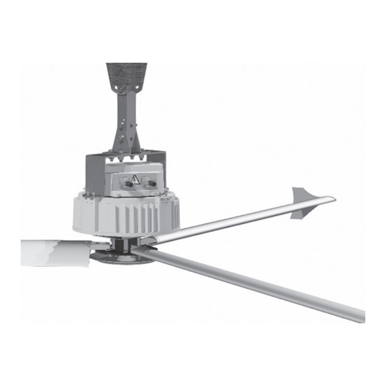
Page 24: Installing Airfoils And Motor Hub
Ne pas insérer d’ o bjets étrangers entre les pales du ventilateur. Airfoil Hardware Kit (supplied): a. (3) 5/16”-18x2” GR 5 Bolt b. (3) 5/16”-18x1-3/4“ GR 5 Bolt c. (12) 5/16” Flat Washer d. (6) 5/16”-18 Nylock Nut Canarm Tri-Lite 3LEC Series... - Page 25 Airfoils 9.1a Attach Airfoils to Hub: Slide airfoil onto struts until airfoil holes and strut holes are aligned. Canarm Tri-Lite 3LEC Series...
- Page 26 Thoroughly inspect the hub, the bolts and brackets within the hub to guarantee clear and proper rotation. If you find that the fan has a bracket that is hitting another object on the hub, contact Canarm for a resolution.
- Page 27 Install wingtips on end of airfoil after airfoil has been securely attached to the strut. Using a Phillips-head screwdriver, fasten wingtip to airfoil using a #6 x 5/8” Flat Phil Screw. Screw Airfoil Wingtip Wingtip Wingtip Hardware Kit (supplied): a. (3) #6 x 5/8” Flat Phil Screw Canarm Tri-Lite 3LEC Series...
-
Page 28: Electrical
Les câbles moteur et de la puissance entrant ne doivent jamais être placés sur le même conduit. Ne pas installer par Canarm Tri-Lite ventilateurs instructions, y compris le câblage, peut être dangereuse, entraîner une défaillance prématurée, et annulera la garantie du fabricant. - Page 29 Câblage ou d’application des erreurs telles que le sous-dimensionnement du contrôleur, une alimentation ca incorrecte ou inadaptée ou des températures ambiantes excessives peuvent provoquer un dysfonctionnement du système de ventilation. Vérifiez que la tension correcte, la phase et puissance avant de commencer l’installation. Canarm Tri-Lite 3LEC Series...
- Page 30 IMPORTANT: Check that the correct input voltage is being sent to the fan. See rating labels on the motor for acceptable voltage. A blown fan due to incorrect input voltage is NOT covered under Canarm Tri-Lite warranty. Canarm Tri-Lite 3LEC Series...
- Page 31 Electrical Installation Manual Single Yoke Wiring Diagram White - Reverse Green - GND-1 Brown - Analog In (0-10v) Red - Speed +10 Volts Connection of wire to pins to be made via soldering. INPUT LINE VOLTAGE Canarm Tri-Lite 3LEC Series...
- Page 32 10.3 Running the Motor Wire The Tri-Lite 3LEC series’ custom designed chassis makes for running the motor wire in an incognito fashion. The motor wire slot on the top of the chassis allows the power wire to be ran through (or affixed to the side) of the extension bar, then conveniently through the top plate of the chassis and directly in to the motor electrical box.
-
Page 33: Troubleshooting
Do not run your controller and sensitive equipment on the same power line. c. Install properly sized EM/RFI filter. d. Contact Customer Service at 1-800-267-4427. 5. LED indicator is not blinking in normal fashion. Please contact Canarm customer service to resolve issue. Canarm Tri-Lite 3LEC Series... -
Page 34: User Servicing Instructions
Lorsque le service ou le remplacement d’un composant dans le ventilateur nécessite le retrait ou la déconnexion d’un dispositif de sécurité, le dispositif de sécurité doit être réinstallé ou remonté comme précédemment installé. Le non-respect peut entraîner des blessures graves. Canarm Tri-Lite 3LEC Series... - Page 35 I-beam or angle irons. 8. Administer proper cleaning techniques such as dusting airfoils, motor, reducer and chassis. If desired, used a water based cleaner to polish airfoils. Maintenance Log: Date: Maintenance Performed Replacement Parts Required Canarm Tri-Lite 3LEC Series...
- Page 36 CANARM LTD PHONE: 1-800-267-4427 FAX: 1-800-263-4598 E-Mail: hvacsales@canarm.ca...
Need help?
Do you have a question about the 3LEC Series and is the answer not in the manual?
Questions and answers