Table of Contents
Advertisement
Quick Links
03/10
INSTALLATION INSTRUCTIONS
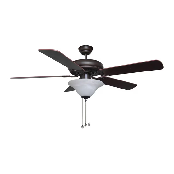
PACIFIC WIND - ENERGY STAR
QUESTIONS OR CONCERNS CONTACT CANARM AT:
1-800-265-1833 (ENGLISH)
1-800-567-2513 (FRENCH)
Monday through Friday 8:00 a.m. to 5:00 p.m. EST
IMPORTANT
FOR YOUR RECORDS, RECORD AND KEEP
THE FOLLOWING INFORMATION
Date of purchase:
Place of purchase:
Model on carton:
I.D.# (bottom of carton):
UPC (bottom of carton):
NOTE: FOR OPTIMUM QUIETNESS, FULLY ASSEMBLE FAN AND RUN FOR 24 HOURS
Advertisement
Table of Contents

Subscribe to Our Youtube Channel
Related Manuals for Canarm PACIFIC WIND


Summary of Contents for Canarm PACIFIC WIND
-
Page 1: Installation Instructions
03/10 INSTALLATION INSTRUCTIONS PACIFIC WIND - ENERGY STAR QUESTIONS OR CONCERNS CONTACT CANARM AT: 1-800-265-1833 (ENGLISH) 1-800-567-2513 (FRENCH) Monday through Friday 8:00 a.m. to 5:00 p.m. EST IMPORTANT FOR YOUR RECORDS, RECORD AND KEEP THE FOLLOWING INFORMATION Date of purchase:... -
Page 2: Safety Precautions
SAFETY PRECAUTIONS 1. Turn off power at main electrical service box before starting installation. 2. Electrical connections must comply with local code ordinances or national electrical codes. 3. Make sure the installation site you choose allows the fan blades to rotate freely without any obstructions. -
Page 3: Assembly Drawing
ASSEMBLY DRAWING 1. wooden joist 2. metal outlet box (not provided) 3. ceiling 4. rubber gasket 5. mounting bracket 6. outlet box screws 7. wood screws & flat washers WITH DOWNROD 8. downrod 9. canopy 10. bolt 11. cotter pin 12. -
Page 4: Installation
INSTALLATION 1. MOUNTING *NOTE: all set screws must be checked and re-tightened where necessary after installation. DOWNROD MOUNT • obtain fan motor • remove cotter pin and bolt from yoke • loosen jam screw in yoke until it is flush with the inside surface •... -
Page 5: Install Mounting Bracket
INSTALLATION 2. INSTALL MOUNTING BRACKET • secure rubber gasket and mounting bracket to metal outlet box using outlet box screws • secure once more by placing two wood screws and flat washers (supplied) through outer slots of mounting bracket and into the wood joist. Leave one of the wood screws sufficiently loose to allow the safety cable to be looped around before final tightening. - Page 6 INSTALLATION 3. HOOKING UP SAFETY CABLE (DOWNROD MOUNT) • obtain fan and place hemisphere of downrod into mounting bracket • rotate fan until the slot in the hemisphere locks into the tab of the mounting bracket • place looped end of safety cable over the wood screw and flat washer not previously tightened (in Step 3) •...
-
Page 7: Electrical Hookup
There are several different wiring combinations that can be used in controlling your ceilingfan to meet your specific requirements. Should the following method not meet your requirements call or visit your nearest Canarm distributor for a full list of fan accessories. - Page 8 INSTALLATION 4. ELECTRICAL HOOKUP (CONTINUED) B. CONNECTING BLACK, WHITE & (BLUE OR RED) WIRES black ground blue/red white • connect white wire from outlet box to white wire from fan using marrette (not supplied). • connect black wire from outlet box to black wire from fan plus (red or blue wire) using a marrette.
- Page 9 INSTALLATION 5. MOUNTING FAN ASSEMBLY • loosen two screws and washers (B) on mounting bracket which correspond with the slots in the canopy • remove two screws and washers (A) on the mounting bracket which correspond with the oblong holes in the canopy. •...
- Page 10 INSTALLATION 6. MOUNTING BLADE BRACKETS TO BLADES A. “DIECAST” BLADE BRACKETS • obtain hardware package containing blade bracket screws and washers. • place fibre washer over screw. • place screw through blade hole and slip a rubber washer over the screw. •...
- Page 11 INSTALLATION 7. MOUNTING BLADE BRACKETS TO BLADES TO MOTOR NOTE: Choice of 4 or 5 blades (option on some fans) Some fans offer the option of four or five blade operation. In these cases there will be two rows of screw holes in the motor casing. The inside row will contain 8 holes for 4 blades and the outside row will contain 10 holes for 5 blade use.
- Page 12 INSTALLATION 8. DETACHABLE LIGHT KITS WARNING: BE SURE TO TURN OFF POWER BEFORE INSTALLING • remove light kit screws and washers. • connect polarized connectors of light kit to corresponding connectors found in switch housing • carefully tuck electrical wires back into switch housing, align light kit with switch housing and secure with three light kit screws and washers.
- Page 13 INSTALLATION 8. DETACHABLE LIGHT KITS (CONTINUED) FIG. E, F: • install proper wattage and type of bulb identified on light housing or shade. • place glass on light housing and secure FIG. E FIG. F white blue white black light kit glass screws fibre washer...
-
Page 14: Cold Weather
CEILING FAN OPERATION WARM WEATHER COLD WEATHER DOWNDRAFT UPDRAFT reverse rotation forward rotation INSTRUCTIONS A ceiling fan has a totally internal switching system for total operation by way of pull chain on a fan/light combination. Three pull chains will exist. One for light, on and off. The second is for fan speeds. -
Page 15: Troubleshooting
• some fan motors are sensitive to signals from solid state variable controls. If solid state controller is used, change to alternative control (See a Canarm representative for a list of available controls.) • allow a 24 hour break in period to eliminate noises Fan wobbles or •... - Page 16 FX: 450-665-0910 CANARM 30 YEAR LIMITED WARRANTY “THANK YOU” for purchasing a Canarm product. It is our policy to furnish you with high quality products at a fair price. With proper installation your fan should provide you with years of money saving comfort.
Need help?
Do you have a question about the PACIFIC WIND and is the answer not in the manual?
Questions and answers