
Related Manuals for Nilfisk-Advance SR 1101 B


Summary of Contents for Nilfisk-Advance SR 1101 B
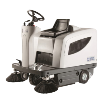
- Page 1 SR 1101 B - SR 1101 P SERVICE MANUAL 1464022000 Edition 1 2009-04 Printed in Italy...
-
Page 3: Table Of Contents
MACHINE LIFTING ..............................3 MACHINE TRANSPORTATION ..........................3 PUSHING OR TOWING THE MACHINE ........................3 OTHER REFERENCE MANUALS AVAILABLE FOR SR 1101 B - SR 1101 P ............3 SAFETY ..................................3 GENERAL SAFETY PRECAUTIONS ........................4 TECHNICAL DATA ..............................6 DIMENSIONS ................................ - Page 4 FUSE REPLACEMENT ............................. 70 DRIVE ELECTRONIC BOARD DISASSEMBLY/REASSEMBLY ................71 TROUBLESHOOTING .............................. 72 COMPONENT LOCATION [for SR 1101 B] ....................... 72 WIRING DIAGRAM [for SR 1101 B] .......................... 75 COMPONENT LOCATION [for SR 1101 P] ....................... 76 WIRING DIAGRAM [for SR 1101 P] .......................... 79...
-
Page 5: General Information
When pushing or towing the machine, carefully follow the relevant instructions given in the User Manual. If you do not follow the given instructions the machine can be damaged. OTHER REFERENCE MANUALS AVAILABLE FOR SR 1101 B - SR 1101 P The following manuals are available at Nilfisk Literature Service Department: –... -
Page 6: General Safety Precautions
GENERAL SAFETY PRECAUTIONS Specific warnings and cautions used to indicate potential damage to people and machines are shown below. DANGER! [For SR 1101 B – SR 1101 P] – Before performing any maintenance, repair, cleaning or replacement procedure disconnect the battery connector, remove the ignition key and engage the parking brake. - Page 7 SERVICE MANUAL ENGLISH GENERAL INFORMATION WARNING! [for SR 1101 B – SR 1101 P] – Carefully read all the instructions before performing any maintenance/repair procedure. – Take all necessary precautions to prevent hair, jewels and loose clothes from being caught by the machine moving parts.
-
Page 8: Technical Data
ENGLISH SERVICE MANUAL GENERAL INFORMATION TECHNICAL DATA Values Dimensions and weights SR 1101 B SR 1101 P Machine length 58.3 in (1480 mm) Machine width (with one side broom) 40.1 in (1020 mm) Machine width (with two side brooms) 47.2 in (1200 mm) Machine maximum height (at the steering wheel) 48.0 in (1220 mm) - Page 9 SERVICE MANUAL ENGLISH GENERAL INFORMATION TECHNICAL DATA (continues) Values Performance data SR 1101 B SR 1101 P Max forward speed 3.7 mph (6 Km/h) Maximum reverse speed 1.8 mph (3 Km/h) Gradeability at full load Main broom rotation speed 550 rpm...
-
Page 10: Dimensions
ENGLISH SERVICE MANUAL GENERAL INFORMATION TECHNICAL DATA (continues) Values Refuelling data SR 1101 B SR 1101 P Fuel tank capacity 6,6 gal (2,5 Liters) Unleaded petrol for motor Fuel type vehicles Values Electrical system data SR 1101 B SR 1101 P... -
Page 11: Maintenance
The following paragraphs give further instructions about the maintenance interventions listed in the following Scheduled Maintenance Table. SCHEDULED MAINTENANCE TABLE [for SR 1101 B] Every 10 Every 50... -
Page 12: Scheduled Maintenance Table [For Sr 1101 P]
ENGLISH SERVICE MANUAL GENERAL INFORMATION SCHEDULED MAINTENANCE TABLE [for SR 1101 P] Every Every Every Every Every Every 50 Maintenance operation On delivery hours hours hours hours hours hours Side and main broom height check and adjustment Dust filter cleaning and integrity check Engine oil level check Engine air filter check/cleaning Skirt height and operation check... -
Page 13: Machine Nomenclature
Waste container handle [*P] Engine model and serial number Removable left door Door knobs [*B]: only on SR 1101 B Main broom right door [*P]: only on SR 1101 P Door knobs Pivoting light (always on when the ignition key is turned to “I”... -
Page 14: Machine Nomenclature [For Sr 1101 B]
ENGLISH SERVICE MANUAL GENERAL INFORMATION MACHINE NOMENCLATURE [for SR 1101 B] S301231 1464022000(1)2009-04 SR 1100S B - SR 1100S P... -
Page 15: Machine Nomenclature [For Sr 1101 B]
SERVICE MANUAL ENGLISH GENERAL INFORMATION MACHINE NOMENCLATURE [for SR 1101 B] S301232 SR 1100S B - SR 1100S P 1464022000(1)2009-04... -
Page 16: Machine Nomenclature [For Sr 1101 P]
ENGLISH SERVICE MANUAL GENERAL INFORMATION MACHINE NOMENCLATURE [for SR 1101 P] S301233 1464022000(1)2009-04 SR 1100S B - SR 1100S P... -
Page 17: Machine Nomenclature [For Sr 1101 P]
SERVICE MANUAL ENGLISH GENERAL INFORMATION MACHINE NOMENCLATURE [for SR 1101 P] S301234 SR 1100S B - SR 1100S P 1464022000(1)2009-04... -
Page 18: Sweeping System
SERVICE MANUAL SWEEPING SYSTEM SWEEPING SYSTEM MAIN BROOM HEIGHT CHECK AND ADJUSTMENT [per SR 1101 B - SR 1101 P] NOTE Brooms of various hardness are available. This procedure is applicable to all types of brooms. Check the main broom for proper ground clearance, proceeding as follows: •... -
Page 19: Side Broom Height Check And Adjustment
SERVICE MANUAL ENGLISH SWEEPING SYSTEM MAIN BROOM DISASSEMBLY/REASSEMBLY [for SR 1101 B - SR 1101 P] NOTE Brooms of various hardness are available. This procedure is applicable to all types of brooms. CAUTION! It is advisable to use protective gloves when replacing the main broom because there can be cutting debris between the bristles. - Page 20 ENGLISH SERVICE MANUAL SWEEPING SYSTEM SIDE BROOM HEIGHT CHECK AND ADJUSTMENT [for SR 1101 B - SR 1101 P] NOTE Brooms of various hardness are available. This procedure is applicable to all types of brooms. Check Check the side brooms for proper ground clearance, proceeding as follows: •...
-
Page 21: Side Broom Disassembly/Reassembly
SERVICE MANUAL ENGLISH SWEEPING SYSTEM SIDE BROOM DISASSEMBLY/REASSEMBLY [for SR 1101 B - SR 1101 P] NOTE Brooms of various hardness are available. This procedure is applicable to all types of brooms. CAUTION! It is advisable to use protective gloves when replacing the side brooms, because there can be cutting debris between the bristles. -
Page 22: Side Broom Lifting Cable Disassembly/Reassembly
ENGLISH SERVICE MANUAL SWEEPING SYSTEM SIDE BROOM LIFTING CABLE DISASSEMBLY/REASSEMBLY [for SR 1101 B - SR 1101 P] Disassembly Drive the machine onto an appropriate lifting hook. Engage the parking brake (20 and 21). Turn the ignition key (2) to “0” position. - Page 23 ENGLISH SWEEPING SYSTEM MAIN BROOM DRIVING BELT VISUAL INSPECTION [for SR 1101 B - SR 1101 P] Drive the machine on a level ground and engage the parking brake (20 and 21). Turn the ignition key (2) to “0” position.
-
Page 24: Main Broom Driving Belt Visual Inspection
ENGLISH SERVICE MANUAL SWEEPING SYSTEM MAIN BROOM DRIVING BELT DISASSEMBLY/REASSEMBLY [for SR 1101 B - SR 1101 P] Disassembly Drive the machine on a level ground and engage the parking brake (20 and 21). Turn the ignition key (2) to “0” position. -
Page 25: Main Broom Gas Spring Disassembly/Reassembly
SERVICE MANUAL ENGLISH SWEEPING SYSTEM MAIN BROOM GAS SPRING DISASSEMBLY/REASSEMBLY [for SR 1101 B - SR 1101 P] Disassembly Remove the main broom. Unscrew the knobs (38) and remove the left door (37). Lower the main broom with the lever (16). -
Page 26: Main Broom Pulley Bearing Replacement
ENGLISH SERVICE MANUAL SWEEPING SYSTEM MAIN BROOM PULLEY BEARING REPLACEMENT [for SR 1101 B - SR 1101 P] Disassembly Drive the machine onto an appropriate lifting hook. Engage the parking brake (20 and 21). Turn the ignition key (2) to “0” position. - Page 27 SERVICE MANUAL ENGLISH SWEEPING SYSTEM MAIN BROOM MOTOR ELECTRICAL INPUT CHECK [for SR 1101 B - SR 1101 P] WARNING! This procedure must be performed by qualified personnel only. Remove the main broom (see the procedure in the relevant paragraph).
-
Page 28: Main Broom Motor Electrical Input Check
ENGLISH SERVICE MANUAL SWEEPING SYSTEM MAIN BROOM MOTOR CARBON BRUSH CHECK AND REPLACEMENT [for SR 1101 B - SR 1101 P] Check Remove the main broom motor (see the procedure in the relevant paragraph). Remove the nuts (A) and the cover (B) at the cabinet bench. - Page 29 SERVICE MANUAL ENGLISH SWEEPING SYSTEM MAIN BROOM MOTOR DISASSEMBLY/REASSEMBLY [for SR 1101 B - SR 1101 P] Disassembly Remove the main broom driving belt (see the procedure in the relevant paragraph). Disconnect the main broom motor (B) electrical connection (A).
-
Page 30: Main Broom Motor Disassembly/Reassembly
ENGLISH SERVICE MANUAL SWEEPING SYSTEM SIDE BROOM MOTOR ELECTRICAL INPUT CHECK [for SR 1101 B - SR 1101 P] NOTE This procedure refers to the right broom: The procedure for the left broom is the same. WARNING! This procedure must be performed by qualified personnel only. -
Page 31: Side Broom Motor Electrical Input Check
SERVICE MANUAL ENGLISH SWEEPING SYSTEM SIDE BROOM MOTOR CARBON BRUSH CHECK AND REPLACEMENT [for SR 1101 B - SR 1101 P] Check Remove the motor of the side broom to be checked (see the procedure in the relevant paragraph). At the cabinet bench, clean the outside of the motor from dirt and dust, then mark the reciprocal position (A) between the cover (B) and the motor body (C). - Page 32 ENGLISH SERVICE MANUAL SWEEPING SYSTEM SIDE BROOM MOTOR DISASSEMBLY/REASSEMBLY [for SR 1101 B - SR 1101 P] NOTE This procedure refers to the right broom: The procedure for the left broom is the same. Disassembly Remove the side broom of the motor to be checked (see the procedure in the relevant paragraph).
-
Page 33: Side Broom Motor Disassembly/Reassembly
SERVICE MANUAL ENGLISH SWEEPING SYSTEM SIDE BROOM ACTIVATION MICROSWITCH ADJUSTMENT AND DISASSEMBLY/REASSEMBLY [for SR 1101 B - SR 1101 P] Preliminary operations Remove the front cover (see the procedure in the relevant paragraph). Adjustment Lift the side brooms with the lever (15), then check that the distance between the microswitch actuator (A) and the activation joint (B) is of 0.08-0.12 (2 -3 mm). -
Page 34: Side Broom Activation Microswitch Adjustment And Disassembly/Reassembly
ENGLISH SERVICE MANUAL SWEEPING SYSTEM MAIN BROOM ACTIVATION MICROSWITCH ADJUSTMENT AND DISASSEMBLY/REASSEMBLY [for SR 1101 B - SR 1101 P] Preliminary operations Remove the front cover (see the procedure in the relevant paragraph). Adjustment Lift the main broom with the lever (16), then check that the distance between the microswitch actuator (A) and the activation joint (B) is of 0.08-0.12 in (2 -3 mm). -
Page 35: Main Broom Activation Microswitch Adjustment And Disassembly/Reassembly
THE MAIN BROOM DOES NOT ROTATE Possible causes: [only for SR 1101 B] Too low battery voltage; warning light (3) on (charge the battery). Worn motor carbon brushes (replace). Faulty motor (repair or replace). -
Page 36: Skirt
SERVICE MANUAL SKIRT SKIRT SKIRT HEIGHT AND OPERATION CHECK AND ADJUSTMENT [for SR 1101 B - SR 1101 P] Drive the machine on a level and adequate ground to check the skirt height. Engage the parking brake (20 and 21). - Page 37 SERVICE MANUAL ENGLISH SKIRT SKIRT HEIGHT AND OPERATION CHECK AND ADJUSTMENT [for SR 1101 B - SR 1101 P] (continues) S301260 S301261 S301262 S301263 SR 1100S B - SR 1100S P 1464022000(1)2009-04...
-
Page 38: Side Skirt Disassembly/Reassembly
ENGLISH SERVICE MANUAL SKIRT SIDE SKIRT DISASSEMBLY/REASSEMBLY [for SR 1101 B - SR 1101 P] Disassembly Drive the machine on a level ground that is suitable for checking the skirt height. Engage the parking brake (20 and 21). Turn the ignition key (2) to “0” position. -
Page 39: Rear Skirt Disassembly/Reassembly
SERVICE MANUAL ENGLISH SKIRT REAR SKIRT DISASSEMBLY/REASSEMBLY [for SR 1101 B - SR 1101 P] Disassembly Drive the machine on a level ground that is suitable for checking the skirt height. Remove the main broom (see the procedure in the relevant paragraph). -
Page 40: Front Skirt Disassembly/Reassembly
ENGLISH SERVICE MANUAL SKIRT FRONT SKIRT DISASSEMBLY/REASSEMBLY [for SR 1101 B - SR 1101 P] Disassembly Drive the machine on a level ground that is suitable for checking the skirt height. Engage the parking brake (20 and 21). Turn the ignition key (2) to “0” position. -
Page 41: Front Skirt Lifting Cable Disassembly/Reassembly
SERVICE MANUAL ENGLISH SKIRT FRONT SKIRT LIFTING CABLE DISASSEMBLY/REASSEMBLY [for SR 1101 B - SR 1101 P] Disassembly Drive the machine on a level ground that is suitable for checking the skirt height. Engage the parking brake by means of the pedal and the lever (20 and 21). -
Page 42: Dust And Debris Collection System
DUST AND DEBRIS COLLECTION SYSTEM DUST AND DEBRIS COLLECTION SYSTEM DUST FILTER CLEANING AND INTEGRITY CHECK [for SR 1101 B - SR 1101 P] NOTE Besides the standard paper filter, optional polyester filters are also available. The following procedure is applicable to each type of filter. - Page 43 SERVICE MANUAL ENGLISH DUST AND DEBRIS COLLECTION SYSTEM DUST FILTER CLEANING AND INTEGRITY CHECK [for SR 1101 B - SR 1101 P] (continues) S301272 S301273 SR 1100S B - SR 1100S P 1464022000(1)2009-04...
-
Page 44: Filter Shaker Operation Check
SERVICE MANUAL DUST AND DEBRIS COLLECTION SYSTEM FILTER SHAKER OPERATION CHECK [for SR 1101 B - SR 1101 P] During machine operation, when the panel filter is supposed to be clogged, press the switch (9) onwards for a few seconds to activate the filter shaker motor and check that the related noise is audible. -
Page 45: Vacuum Fan Disassembly/Reassembly
Drive the machine on a level ground and engage the parking brake (20 and 21). Turn the ignition key (2) to “0” position. [For SR 1101 B] Unplug the battery connector (62) Disengage the hook (35) by pulling its lower end. - Page 46 ENGLISH SERVICE MANUAL DUST AND DEBRIS COLLECTION SYSTEM VACUUM FAN DISASSEMBLY/REASSEMBLY (continues) S301276 1464022000(1)2009-04 SR 1100S B - SR 1100S P...
-
Page 47: Troubleshooting
SERVICE MANUAL ENGLISH DUST AND DEBRIS COLLECTION SYSTEM TROUBLESHOOTING [for SR 1101 B - SR 1101 P] POOR OPERATION OF THE VACUUM FAN Possible causes: The dust filter is obstructed (clean). Vacuum fan with broken/worn fins (replace the vacuum fan). -
Page 48: Steering And Braking System
SERVICE MANUAL STEERING AND BRAKING SYSTEM STEERING AND BRAKING SYSTEM STEERING CHAIN CHECK AND CLEANING [for SR 1101 B - SR 1101 P] NOTE The steering chain is not adjustable. Drive the machine on a level ground and engage the parking brake (20 and 21). -
Page 49: Steering Chain Disassembly/Reassembly
SERVICE MANUAL ENGLISH STEERING AND BRAKING SYSTEM STEERING CHAIN DISASSEMBLY/REASSEMBLY [for SR 1101 B - SR 1101 P] NOTE The steering chain is not adjustable. Disassembly Drive the machine on a level ground and engage the parking brake (20 and 21). -
Page 50: Service And Parking Brake Check And Adjustment
SERVICE MANUAL STEERING AND BRAKING SYSTEM SERVICE AND PARKING BRAKE CHECK AND ADJUSTMENT [for SR 1101 B - SR 1101 P] Drive the machine on a level ground. Do not engage the parking brake (20 and 21), but check that the machine cannot move independently. -
Page 51: Brake Control Cable Replacement
SERVICE MANUAL ENGLISH STEERING AND BRAKING SYSTEM BRAKE CONTROL CABLE REPLACEMENT [for SR 1101 B - SR 1101 P] Disassembly Drive the machine on a level ground. Do not engage the parking brake (20 and 21), but check that the machine cannot move independently. -
Page 52: Brake System Disassembly/Reassembly
ENGLISH SERVICE MANUAL STEERING AND BRAKING SYSTEM BRAKE SYSTEM DISASSEMBLY/REASSEMBLY [for SR 1101 B - SR 1101 P] Disassembly Drive the machine on a level ground. Do not engage the parking brake (20 and 21), but check that the machine cannot move independently, by applying wedges to the rear wheels. -
Page 53: Drive System
SERVICE MANUAL ENGLISH DRIVE SYSTEM DRIVE SYSTEM DRIVE MOTOR ELECTRICAL INPUT CHECK [for SR 1101 B - SR 1101 P] WARNING! This procedure must be performed by qualified personnel only. Drive the machine on a level ground. Engage the parking brake (20 and 21). -
Page 54: Drive Motor Carbon Brush Check And Replacement
ENGLISH SERVICE MANUAL DRIVE SYSTEM DRIVE MOTOR CARBON BRUSH CHECK AND REPLACEMENT [for SR 1101 B - SR 1101 P] Check Remove the drive system (see the procedure in the relevant paragraph). Remove the nuts (A) and the cover (B) at the cabinet bench. -
Page 55: Drive System Disassembly/Reassembly
SERVICE MANUAL ENGLISH DRIVE SYSTEM DRIVE SYSTEM DISASSEMBLY/REASSEMBLY [for SR 1101 B - SR 1101 P] Disassembly Drive the machine on a level ground and engage the parking brake (20 and 21). Turn the ignition key (2) to “0” position. -
Page 56: Drive Motor Disassembly/Reassembly
ENGLISH SERVICE MANUAL DRIVE SYSTEM DRIVE MOTOR DISASSEMBLY/REASSEMBLY [for SR 1101 B - SR 1101 P] Disassembly Remove the drive system (see the procedure in the relevant paragraph). At the cabinet bench, remove the screws (A) and the wheels (B), then recover the keys and the washers. -
Page 57: Forward/Reverse Gear Pedal Disassembly/Reassembly
SERVICE MANUAL ENGLISH DRIVE SYSTEM FORWARD/REVERSE GEAR PEDAL DISASSEMBLY/REASSEMBLY [for SR 1101 B - SR 1101 P] Disassembly Drive the machine on a level ground. Engage the parking brake (20 and 21). Remove the pedal fastening screws (A). Slightly lift the pedal (B) and disconnect the electrical connector (C). -
Page 58: Forward/Reverse Gear Pedal Potentiometer Check And Adjustment
ENGLISH SERVICE MANUAL DRIVE SYSTEM FORWARD/REVERSE GEAR PEDAL POTENTIOMETER CHECK AND ADJUSTMENT [for SR 1101 B - SR 1101 P] Remove the forward/reverse gear pedal (see the procedure in the relevant paragraph). At the cabinet bench, remove the screws (A) and the guard (B). -
Page 59: Troubleshooting
DRIVE BOARD ERROR CODES The warning led (70) stays on when the drive system works correctly with the machine in the following conditions: – Ignition key (2) in “I” position (for SR 1101 B) – Engine running (for SR 1101 B) –... -
Page 60: Table Of Drive Board Error Codes
ENGLISH SERVICE MANUAL DRIVE SYSTEM TABLE OF ERROR CODES SIGNALLED BY THE DRIVE BOARD LED LED CODES ERROR DESCRIPTION (REMEDY) Notes Reference LED flashing type LED off Control system malfunction, or drive fuse (FT) blown, or seat microswitch activated, or electrical cable disconnected (check the drive board wire harness) LED on Control system operating, no malfunctions detected... -
Page 61: Battery Charging System
SERVICE MANUAL ENGLISH BATTERY CHARGING SYSTEM BATTERY CHARGING SYSTEM ENGINE RPM CHECK AND ADJUSTMENT [for SR 1101 P] WARNING! This procedure must be performed by qualified personnel only. Check With warm engine (engine running for about 20 minutes), record engine speed with an appropriate indicator applied on the ignition spark plug electrical cable. -
Page 62: Check And Tension Of The Belt From The Engine To The Dynamotor [For Sr 1101 P]
ENGLISH SERVICE MANUAL BATTERY CHARGING SYSTEM CHECK AND TENSION OF THE BELT FROM THE ENGINE TO THE DYNAMOTOR [for SR 1101 P] Check Drive the machine on a level ground. Engage the parking brake (20 and 21). Turn the ignition key (2) to “0” position. Open the hood (24) with a handle (55). - Page 63 SERVICE MANUAL ENGLISH BATTERY CHARGING SYSTEM CHECK AND TENSION OF THE BELT FROM THE ENGINE TO THE DYNAMOTOR [for SR 1101 P] (continues) 2 / 3 mm S301294 S301295 SR 1100S B - SR 1100S P 1464022000(1)2009-04...
-
Page 64: Battery And Dynamotor Electrical Voltage Check [Per Sr 1101 P]
ENGLISH SERVICE MANUAL BATTERY CHARGING SYSTEM BATTERY AND DYNAMOTOR ELECTRICAL VOLTAGE CHECK [per SR 1101 P] WARNING! This procedure must be performed by qualified personnel only. Lift the hood (24) with a handle (55). Bypass the wiring driver’s seat safety microswitch for engine starting. WARNING! Pay attention to the moving parts while performing the following steps. -
Page 65: Dynamotor Carbon Brush Check And Replacement [For Sr 1101 P]
SERVICE MANUAL ENGLISH BATTERY CHARGING SYSTEM DYNAMOTOR CARBON BRUSH CHECK AND REPLACEMENT [for SR 1101 P] Check Open the hood (24) with a handle (55). Remove the dynamotor carter protection (A) then recover the screws and the washers (B). Remove dust and dirt from the motor exterior part; then disengage and remove the clamp (C). Lift the retaining spring (D) of each carbon brush, then remove the four carbon brushes (E). -
Page 66: Dynamotor Disassembly/Reassembly [For Sr 1101 P]
ENGLISH SERVICE MANUAL BATTERY CHARGING SYSTEM DYNAMOTOR DISASSEMBLY/REASSEMBLY [for SR 1101 P] Disassembly Drive the machine on a level ground and engage the parking brake (20 and 21). Turn the ignition key (2) to “0” position. Open the hood (24) with a handle (55). Disconnect the battery caps (59). -
Page 67: Engine Manual Starting (In Case Of Emergency) With Completely Discharged Betteries [For Sr 1101 P]
SERVICE MANUAL ENGLISH BATTERY CHARGING SYSTEM ENGINE MANUAL STARTING (IN CASE OF EMERGENCY) WITH COMPLETELY DISCHARGED BETTERIES [for SR 1101 P] Engage the parking brake (20 and 21). Open the hood (24) with a handle (55). Making a bridge wiring over the wiring harness bonnet in the attack near the seat cable micro. Turn the ignition key (2) to “I”... -
Page 68: Other Systems
OTHER SYSTEMS OTHER SYSTEMS SCREW AND NUT TIGHTENING CHECK [for SR 1101 B - SR 1101 P] Drive the machine on a level ground and engage the parking brake by means of the pedal and the lever (20 and 21). -
Page 69: Front Cover Disassembly/Reassembly
SERVICE MANUAL ENGLISH OTHER SYSTEMS FRONT COVER DISASSEMBLY/REASSEMBLY [for SR 1101 B - SR 1101 P] Disassembly Drive the machine on a level ground and engage the parking brake by means of the pedal and the lever (20 and 21). - Page 70 ENGLISH SERVICE MANUAL OTHER SYSTEMS FRONT COVER DISASSEMBLY/REASSEMBLY [for SR 1101 B - SR 1101 P] (continues) S301298 S301299 S301300 1464022000(1)2009-04 SR 1100S B - SR 1100S P...
-
Page 71: Seat Running Consent Microswitch Disassembly/Reassembly
SERVICE MANUAL ENGLISH OTHER SYSTEMS SEAT RUNNING CONSENT MICROSWITCH DISASSEMBLY/REASSEMBLY [for SR 1101 B - SR 1101 Disassembly Drive the machine on a level ground and engage the parking brake (20 and 21). Turn the ignition key (2) to “0” position. -
Page 72: Electrical System
BATTERY CHARGING [per SR 1101 B] See User Manual. FUSE REPLACEMENT [for SR 1101 B - SR 1101 P] Drive the machine on a level ground and engage the parking brake (20 and 21). Turn the ignition key (2) to “0” position. -
Page 73: Drive Electronic Board Disassembly/Reassembly
SERVICE MANUAL ENGLISH ELECTRICAL SYSTEM DRIVE ELECTRONIC BOARD DISASSEMBLY/REASSEMBLY [for SR 1101 B - SR 1101 P] Disassembly Drive the machine on a level ground and engage the parking brake (20 and 21). Turn the ignition key (2) to “0” position. -
Page 74: Troubleshooting
ENGLISH SERVICE MANUAL ELECTRICAL SYSTEM TROUBLESHOOTING [for SR 1101 B - SR 1101 P] See the previous chapters related to the use of the electrical system. Other possible causes: Discharged battery or not-efficient connections (charge the battery or clean the connections). - Page 75 SERVICE MANUAL ENGLISH ELECTRICAL SYSTEM COMPONENT LOCATION [per SR 1101 B] (continues) SW5-ES5 S301309 SR 1100S B - SR 1100S P 1464022000(1)2009-04...
- Page 76 ENGLISH SERVICE MANUAL ELECTRICAL SYSTEM COMPONENT LOCATION [per SR 1101 B] (continues) F1 F2 F4 F5 F6 S301310 1464022000(1)2009-04 SR 1100S B - SR 1100S P...
-
Page 77: Wiring Diagram [For Sr 1101 B]
SERVICE MANUAL ENGLISH ELECTRICAL SYSTEM WIRING DIAGRAM [for SR 1101 B] (continues) S301313 SR 1100S B - SR 1100S P 1464022000(1)2009-04... -
Page 78: Component Location [For Sr 1101 P]
ENGLISH SERVICE MANUAL ELECTRICAL SYSTEM COMPONENT LOCATION [per SR 1101 P] Colour codes Batteries Black Pivoting light (optional) Blue Engine frame Brown Reverse gear warning buzzer/horn Green Diode board Grey Drive electronic board Orange Engine safety relay Pink Main broom relay Filter shaker relay Violet Vacuum system relay... - Page 79 SERVICE MANUAL ENGLISH ELECTRICAL SYSTEM COMPONENT LOCATION [per SR 1101 P] (continues) SW5-ES5 S301311 SR 1100S B - SR 1100S P 1464022000(1)2009-04...
- Page 80 ENGLISH SERVICE MANUAL ELECTRICAL SYSTEM COMPONENT LOCATION [per SR 1101 P] (continues) ES3 T1 ES7 ES1 ES4 F1 F2 F4 F5 F6 S301312 1464022000(1)2009-04 SR 1100S B - SR 1100S P...
-
Page 81: Wiring Diagram [For Sr 1101 P]
SERVICE MANUAL ENGLISH ELECTRICAL SYSTEM WIRING DIAGRAM [for SR 1101 P] S301314 SR 1100S B - SR 1100S P 1464022000(1)2009-04...
Need help?
Do you have a question about the SR 1101 B and is the answer not in the manual?
Questions and answers