Table of Contents
Advertisement
Electronic Service
Manuals
This electronic document is provided as a service to our custom-
ers. We do not create the contents of the information contained in
this document. Should you have detailed questions pertaining to
the information contained in this document, you may contact Michco,
or the manufacturer which provided the original information in this
electronic deliverable. Michco's only part in this electronic deliver-
able was the electronic assembly process.
You may contact Michco through the following methods:
Phone (517) 484-9312 or (800) 331-3339 MI, OH, IN only
2011 N. High St. -- Lansing, Michigan -- 48906
Fax: (517) 484-9836
Email: CustServ@Michco.com
Web site: www.Michco.Com
Parts Web site: www.FloorMachineParts.Com
Order Parts on Line at:
www.FloorMachineParts.Com
Directly to Parts & Service:
By Email:
Shop@Michco.com
By Fax: (517) 702-2041
By Voice: Use numbers above.
Serving the Cleaning Industry Since 1922
Notice: All copyrighted material remains property of original owners, all trademarks are property of respective
owners. Manuals are subject to Manufacturer's reproduction limitations. Originals or reproductions were provided
by manufacturers through a request. We make no warranty as to the correctness of information provided in this
document and you assume all risk.
Advertisement
Table of Contents

Related Manuals for Nilfisk-Advance SR 1300 B


Summary of Contents for Nilfisk-Advance SR 1300 B
- Page 1 Electronic Service Manuals This electronic document is provided as a service to our custom- ers. We do not create the contents of the information contained in this document. Should you have detailed questions pertaining to the information contained in this document, you may contact Michco, or the manufacturer which provided the original information in this electronic deliverable.
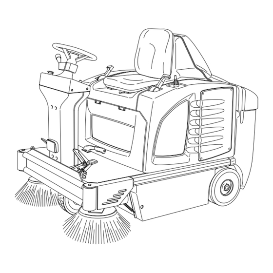
- Page 2 SR 1300 B/ECO OPERATOR MANUAL Advance MODELS 908 3013 010, 908 3301 010 FORM No. 56041481(1)00-03...
-
Page 3: Table Of Contents
INDEX 56041481 INTRODUCTION / GENERAL INFORMATION................. 1 UNPACKING ........................... 2 TECHNICAL DATA .......................... 3 DESCRIPTION OF COMMANDS AND CONTROL PANEL ............... 4 PRELIMINARY OPERATIONS......................5-7 USE ..............................8-15 TURNING THE MACHINE ON....................8 START/STOP OF THE GASOLINE ENGINE................. 8 USE OF THE WORKING PROGRAMS..................9 FURTHER PERFORMANCES OF THE MACHINE WITH GASOLINE ENGINE ...... -
Page 4: Introduction / General Information
Use the space below to note the Model and Serial Number of your machine for future reference. Model: SR 1300 ECO Prod. No.: 908 3301 010 Model: SR 1300 B Prod. No.: 908 3013 010 Serial No.: 94103496 Max axel rear: Kg 280,5/618 lb Serial No.: XXXXXXXXX... -
Page 5: Unpacking
UNPACKING 56041481 Please check that the following items be supplied with the machine: 1 - envelope with cables for batteries and connector for battery-charger. 2 - technical documents (Spare Parts Catalogue, Manual for Use and Maintenance and - for the gasoline version only - Use and Maintenance Manual of the engine). -
Page 6: Technical Data
TECHNICAL DATA 56041481 VERSION SR 1300 ECO SR 1300B Voltage Engine model Vanguard OHV Nominal Power at 3600 4 Hp - 2,95 Kw Displacement 126 cc (7,69 cu.in) Start Automatic Drive electrical motor 750W - 315 RPM 750W - 315 RPM Main brush electrical 500W - 1600 RPM 500W - 1600 RPM... -
Page 7: Description Of Commands And Control Panel
DESCRIPTION OF COMMANDS AND 56041481 CONTROL PANEL 1 - Voltmeter/hourmeter push button 10 - ON/OFF main key switch 2 - 4 digits display 11 - Start/Stop push button for gasoline 3 - Button for selection/indicator of engine working program P1 12 - Selection of forw./reverse speed, light 4 - Button for selection/indicator of ON/OFF, horn... -
Page 8: Preliminary Operations
PRELIMINARY OPERATIONS 56041481 The machine-both the gasoline and the battery version-is equipped with a 24 Volt group of batteries. Depending on the country where the machine is sold three possibilities can occur: 1 - the battery is supplied with the machine and it is set, complete with acid solution 2 - the battery is supplied with the machine and it is set, but not complete with acid solution... - Page 9 PRELIMINARY OPERATIONS 56041481 FRONT OF MACHINE FRONT OF MACHINE 2 - If the batteries are installed but not filled with acid INSTALL BATTERIES ACCORDING INSTALL BATTERIES ACCORDING solution they must be filled with a solution of TO DIAGRAM BELOW. OBSERVE TO DIAGRAM BELOW.
-
Page 10: Preliminary Operations
PRELIMINARY OPERATIONS 56041481 Connect the battery connector to the machine. 3 - If the machine is not equipped with batteries they must be procured and mounted. It is recommended to get the assistance of qualified personnel to chose and set the batteries. The electrical cables supplied with the machine can be used for the connection of the batteries. -
Page 11: Use
56041481 TURNING THE MACHINE ON Insert the ignition key into the panel and turn it clockwise: the display will show only zeros and after about three seconds the battery voltage will appear. Note : the temporary lighting of the side brush indicators and the short sound from the reverse speed acoustic indicator correspond to a normal behaviour. -
Page 12: Use Of The Working Programs
56041481 USE OF THE WORKING PROGRAMS When the machine has been turned on and, eventually, after the start of the gasoline engine, it is possible to choose one of the two working programs P1 and P2 pressing the relevant button: P1 is the “light cleaning program”... - Page 13 56041481 It is possible to adjust the side brush/es turning speed by means of the dedicated knob. Select the forward speed by means of the command lever. Press the accelerator pedal to start the job. Note: by releasing the accelerator pedal (or setting the command lever to the neutral position) the automatic switch off of all functions will occur within 8 seconds (Auto Power Off) except the...
- Page 14 56041481 In order to get an efficient cleaning function the panel filter must always be clean. Press the filter-shaker button, even if the machine is working. This operation must be repeated every 10 to 15 minutes, depending on the kind of rubbish to be swept; before emptying the dirt container and, in any case, at the end of the work.
- Page 15 56041481 A safety device is located inside the operator seat: the drive function - either forward or reverse - is disabled as soon as the operator will stand up or leave the seat. At the end of the job turn off the selected working program (P1 or P2) and switch the gasoline engine Off pressing the button shown in the figure.
- Page 16 56041481 To lift the tank move the lever rearward as shown in the figure. Approach the rubbish-bin. Release the lever that places itself centrally, push it on the outside until the tank door is opened to allow the discharge of the picked up material.
- Page 17 56041481 After discharging, release the lever that will move to the central position so to close the rear tank door. Move away from the rubbish bin, then move the lever onward, press again the red button so that the tank comes back to the starting position (lowered).
-
Page 18: Further Performances Of The Machine With Gasoline Engine
56041481 In the event that the machine must be pushed in Off condition or without batteries turn the proper key counter-clockwise (see the figure), in order to disengage the electrical drive motor and disable the self-breaking function. Turn and eventually remove the red key that can be seen after lifting the lid of the engine/battery compartment. -
Page 19: Side Brushes Adjustment And Replacement
SIDE BRUSHES ADJUSTMENT AND 56041481 REPLACEMENT Warning: the following operations must be done with the machine in Off condition and the master key out, on a flat floor. When the side brush is worn its height must be adjusted. Loosen the knob. Turn the adjusting disk and tighten the knob. -
Page 20: Main Brush Replacement
MAIN BRUSH REPLACEMENT 56041481 Warning: the following operations must be done with the machine in Off condition and master key out. This machine is equipped with an automatic control of the main brush pressure; this also means that the position of the main brush is automatically adjusted (no need of manual adjustment). - Page 21 MAIN BRUSH REPLACEMENT 56041481 Remove the worn brush. Remove the plastic adapter from the worn brush, using a screw driver. Fix the plastic adapter to the new brush: pay attention to the correct angle of the brush bristles (look at the next figure).
-
Page 22: Filter Cleaning And Replacement
FILTER CLEANING AND REPLACEMENT 56041481 The panel filter requires a regular cleaning. Lift the hopper just to get access to the two rubber locks used to hold the external cover. Remove the cover. Disconnect the electric cable of the filter-shaker motor and suction fan (the machine must first be turned off and the key out). - Page 23 FILTER CLEANING AND REPLACEMENT 56041481 After cleaning fit the filter and the suction fan holder. Tighten the two knobs and locking nuts and reconnect the electric cable.. If the filter is damaged or can not be properly cleaned replace it with a new one. Ask to your supplier for the new spare part.
-
Page 24: Maintenance
MAINTENANCE 56041481 BATTERIES: CONTROL AND RECHARGE Make a frequent check of the electrolyte level inside every battery cell. The battery compartment is under the operator seat; lift the lid and open the caps of all the battery cells: when necessary fill up the cells with distilled water. -
Page 25: Brakes Adjustment
MAINTENANCE 56041481 BRAKES ADJUSTMENT When the pedal brake and/or the parking brake reach a low efficiency operation some adjustments can be done: on the rear wheels - loosen the locking nut A - turn adjuster B - tighten locking nut A. FRONT LAMP REPLACEMENT In order to replace the front lamp: - remove the transparent cover... -
Page 26: Maintenance Of The Gasoline Engine
MAINTENANCE 56041481 MAINTENANCE OF THE GASOLINE ENGINE First: read thoroughly the Use and Maintenance Manual of the engine. Here below some recommendations are pointed out. Check the engine oil level twice per week. In order to check the engine oil level the right side panel (grate) must be removed, or simply slid up;... - Page 27 MAINTENANCE 56041481 Clean or replace the air filter according to the instructions of the engine Manual or whenever it is necessary. In order to get access to the air filter the engine assembly must be slid out; to slide out the engine assembly first the right side wall of the machine must be removed (see engine oil replacement procedure for right side wall removal).
-
Page 28: Summary Of Maintenance Controls (Battery Version)
SUMMARY OF MAINTENANCE 56041481 CONTROLS (battery version) Warning: the following interventions must be done with machine in Off condition and master key out. All the periodic maintenance operations must be performed by skilled personnel or by an authorized service centre. Note: the battery life will depend on a good periodic maintenance (check of the level of the electrolyte and of battery voltage). -
Page 29: Summary Of Maintenance Controls (Gasoline Version)
SUMMARY OF MAINTENANCE 56041481 CONTROLS (gasoline version) Warning: the following interventions must be done with machine in Off condition and master key out. All the periodic maintenance operations must be performed by skilled personnel or by an authorized service centre. Every maintenance intervention on the gasoline engine must be performed in agreement with the engine User Manual. -
Page 30: Optional Items
OPTIONAL ITEMS 56041481 High capacity batteries for machine with gasoline engine High capacity batteries for machine without gasoline engine Battery charger Different types of main bushes and side brushes Polyester panel filter (it can be washed) In order to have more detailed information for all the optional items get in touch with your supplier of the machine. -
Page 31: Safety Functions And Trouble-Shooting
SAFETY FUNCTIONS AND TROUBLE- 56041481 SHOOTING The machine is equipped with many safety devices and functions which have been described in the USE TO PUSH paragraphs (both for gasoline and electrical versions). For instance the automatic stop of all functions to avoid the deep discharge of the battery has been mentioned;... - Page 32 Nilfisk-Advance, Inc. 14600 21st Avenue North Plymouth, MN, 55447-3408 www.nilfisk-advance.com Phone: 800-989-2235 Fax: 800-989-6566 ©1999 Nilfisk-Advance, Inc. Plymouth, MN, 55447-3408 Printed in the U.S.A.
Need help?
Do you have a question about the SR 1300 B and is the answer not in the manual?
Questions and answers