
Related Manuals for Thermo Scientific BF51731


Summary of Contents for Thermo Scientific BF51731
- Page 1 Thermo Fisher Scientific Lindberg/Blue M LGO 1200°C Box Furnace Models: BF51731 and BF51732 (C/BC) Installation and Operational Manual 304257H02 Rev. A November, 2020...
- Page 2 © 2020 Thermo Fisher Scientific Inc. All rights reserved. Thermo Fisher Scientific Inc. provides this document to its customers with a product purchase to use in the product operation. This document is copyright protected and any reproduction of the whole or any part of this document is strictly prohibited, except with the written authorization of Thermo Fisher Scientific Inc.
-
Page 3: Table Of Contents
Table of Contents Table of Contents Chapter 1 Safety Notes ..............1-5 Explanation of Symbols . - Page 4 Table of Contents Soft Start Timer ..............6-40 Delayed Switch On Timer .
- Page 5 Figure 4 Preventing Chimney Effect ......................4-20 Figure 5 Gas Inlet Tube Assembly ......................4-21 Figure 6 Thermocouple..........................9-61 Figure 7 Controller Electrical Panel ......................9-62 Figure 8 Wiring Diagram (BF51731, BF51732) ..................12-67 1200°C Box Furnace 304257H02 | 3...
- Page 6 Figures 304257H02 1200°C Box Furnace...
-
Page 7: Chapter 1 Safety Notes
Safety Notes Explanation of Symbols This symbol when used alone indicates important operating instructions which reduce the risk of injury or poor performance of the unit. DANGER : Indicates a hazardous situation which, if not avoided, will result in death or serious injuries. - Page 8 | Safety Notes Chapter 1 This symbol indicates power is ON. This symbol indicates power is OFF. This symbol indicates Alternating current. This symbol indicates Earth ground power. This symbol indicates Protective conductor terminal. 1-6 | 304257H02 1200°C Box Furnace...
-
Page 9: Safety Considerations
Safety Notes | Chapter 1 Safety Considerations DANGER : Do not modify or use equipment in a manner other than expressly intended. Modification of equipment other than that for which it is explicitly designed could cause severe injury or death. Any customer after-market retrofit violates the warranty of the equipment. - Page 10 | Safety Notes Chapter 1 WARNING : When installing, maintaining, or removing the insulation, the following precautions will minimize airborne dust and fiber: Keep personnel not involved in the installation out of the area. Use a good vacuum to clean area and equipment. Use a dust suppressant if ...
-
Page 11: Standards And Directives
Safety Notes | Chapter 1 Standards and Directives The box furnaces complies with the following standards and guidelines: European Union The European voltage models of this product meet all the applicable requirements of the European Directives and therefore display the CE Marking. - Page 12 | Safety Notes Chapter 1 Evaluation of Chemicals - Regulations and Directives Proposition 65 - California WARNING : Cancer and Reproductive Harm - www.P65Warnings.ca.gov REACH - Europe Thermo Fisher Scientific are committed to meeting all compliance obligations to evaluate, communicate, and register any Substances of Very High Concern (SVHC), and finding alternates where appropriate.
-
Page 13: Chapter 2 Introduction
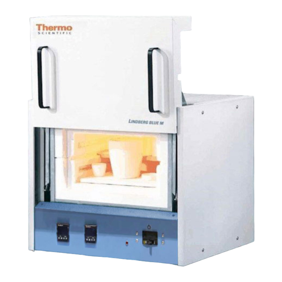
Introduction 1200°C Box Furnace Figure 1 The Thermo Fisher Scientific BF51731, BF51732 is a reliable, energy efficient 1200°C ® laboratory box furnace. The heating elements and low thermal mass Moldatherm insulation provide fast duty cycles, energy conservation, and efficient programming. -
Page 14: Intended Use
| Introduction Chapter 2 Main power ON/OFF switch and power indicator on control panel. Double wall construction. Front control panel is recessed at the top. This feature provides easy viewing of the control LED and protection for the control instrumentation. Intended Use This furnace is intended as a general purpose laboratory, ashing, and heat treating furnace at 1200°C for continuous (over 3 hours) or intermittent (under 3 hours) use. -
Page 15: Specifications
Introduction | Chapter 2 Specifications Table 1 BF51731, BF51732 Laboratory Box Furnaces BF51731C-1 BF51732C-1 BF51732BC-1 Model BF51731BC-1 BF51731COMC-1* BF51732COMC-1* BF51732BCOMC-1* 16.4 L 16.4 L 16.4 L 16.4 L Capacity (0.6 cu. ft.) (0.6 cu. ft.) (0.6 cu. ft.) (0.6 cu. ft.) Temp. - Page 16 | Introduction Chapter 2 2-14 1200°C Box Furnace 304257H02...
-
Page 17: Chapter 3 Pre-Installation
Pre-Installation Unpacking Carefully unpack and inspect the unit and all accessories for damage, if you find any damage, keep the packing materials and immediately report the damage to the carrier. We will assist you with your claim, if requested. Do not return goods to Thermo Fisher Scientific without written authorization. -
Page 18: Environmental Conditions
| Pre-Installation Chapter 3 Environmental Conditions Indoor Use Only. Class of Equipment Class I Mains Supply Mains supply voltage fluctuations not to exceed ±10% of the nominal voltage. Fluctuations Operating The recommended ambient temperature is 17°C to 27°C (62.6°F to 80.6°F); 20% to 80% relative humidity, non-condensing. -
Page 19: Chapter 4 Installation
Installation CAUTION : Be sure ambient temperature does not exceed 40°C (104°F). Ambient above this level may result in damage to the controller. The recommended ambient temperature is 17°C to 27°C (62.6°F to 80.6°F). CAUTION : Allow at least 3" (7.62 cm) of space between the furnace, at least 12"... -
Page 20: Mains Electrical/Thermocouple Check
| Installation Chapter 4 Furnace installation requires L1, L2, and ground wire (not provided). NOTE For Europe, L2 connection at furnace is wired to Neutral. NOTE Electrical installation must be performed by a qualified electrician. Consult local electrical codes for proper sizing of power and control wiring. 3. -
Page 21: Exhaust Vent
Installation | Chapter 4 5. Replace the small back panel on the furnace and secure with the screws. 6. Connect Mains electrical to facility ground outlet meeting the unit specifications found on the data tag. Exhaust Vent Flow from the exhaust vent on the top of the unit can be adjusted by inserting or removing the plug provided. -
Page 22: Atmosphere Inlet
| Installation Chapter 4 Figure 4 Preventing Chimney Effect Atmosphere Inlet Furnaces have a factory-installed air/atmosphere inlet. Most inert atmospheres (i.e. nitrogen, argon, and helium) can be safely run in this box furnace. However, maximum temperatures may be derated depending on atmosphere. An initial burn-in period in air is recommended. -
Page 23: Atmosphere Inlet Port
Installation | Chapter 4 Atmosphere Inlet Port The atmosphere inlet tube assembly has been packaged separately to avoid breakage during shipping and handling. Even if you do not intend to use the gas inlet, you must install the assembly before operating the furnace. - Page 24 | Installation Chapter 4 How to Install Hearth Plates Hearth plates are designed with grooved surface. The grooved surface must be positioned facing the chamber floor. How to Install Shelves Slide into middle slot opening on heater assembly. ...
-
Page 25: Chapter 5 Start-Up
Start-Up WARNING : After transport and decommissioning, or storage under humid conditions a drying-out process must be performed due to hydroscopic nature of the ceramic fiber insulation. During the drying-out process the equipment cannot be assumed to meet all the safety requirements of the IEC 61010-2-010 standard. WARNING : Observe the following precautions when operating the furnace: Never stand in front of an open furnace. -
Page 26: Door Seal Check
| Start-Up Chapter 5 12. Highly recommended to Auto Tune unit for application prior to use refer to section “Auto Tuning” . Refer to section “Eurotherm 3216 Controller” for detailed start up steps. Door Seal Check It is very important to check the door seal before using this furnace. Door seal integrity is essential to maintain temperature uniformity and to prevent fumes being released into the area surrounding the furnace. -
Page 27: Chapter 6 1X8 Segment And 5X16 Segment Programmable Models W/Otp
1x8 segment and 5x16 Segment Programmable Models w/OTP Eurotherm 3216 Controller The Eurotherm 3216c and 3216p temperature controllers senses the furnace's chamber air temperature (the PV or process value) and provides the heat needed to reach the required set point. There are two choices of controls used in the various furnaces models: The 3216c controller is a basic single setpoint and Timer (1-program 8-segment or Dwell timer or Delay timer). -
Page 28: Operator Interface & Home Display
| 1x8 segment and 5x16 Segment Programmable Models w/OTP Chapter 6 Operator Interface & HOME Display When the controller is turned ON, it will perform a brief self-test and then display the HOME Display page. The measured value (process value) is found in the upper display and the set point is found in the lower display. -
Page 29: Operator Buttons
1x8 segment and 5x16 Segment Programmable Models w/OTP | Chapter 6 Operator Buttons Press to select a new list of parameters and from any display - press PAGE to return to the HOME Page. Press to select new parameter from the page header. If held down it will continuously scroll through parameters. -
Page 30: Alternate Set Point Selection (Sp2)
| 1x8 segment and 5x16 Segment Programmable Models w/OTP Chapter 6 Alternate Set Point Selection (SP2) 1. Press the SCROLL button from HOME display until SP.SEL is displayed. 2. Press UP or DOWN button to select SP1 or SP2. If SP2 is selected, then SPX beacon will appear on the HOME display indicating the action of alternate set point in use. -
Page 31: View Or Change The Display Units
1x8 segment and 5x16 Segment Programmable Models w/OTP | Chapter 6 Complete the following steps to change the ramp rate of SSP. 6. Press the SCROLL button until SP.RAT is displayed. 7. Press UP or DOWN button until the desired ramp rate is indicated on the display. -
Page 32: Auto Tuning
| 1x8 segment and 5x16 Segment Programmable Models w/OTP Chapter 6 d. (NONE): No units displayed e. (PERC): Percent NOTE Do not use nonE & PErc, they are used to measure other applications types other than temperature. Auto Tuning In Auto Tuning the characteristics (PID parameters) of the controller are matched to the characteristics of the product load in order to obtain good control. -
Page 33: Parameter List
1x8 segment and 5x16 Segment Programmable Models w/OTP | Chapter 6 5. Press the PAGE button to return to the HOME display. The display will flash TUNE to indicate that tuning is in progress. The auto tune is completed when the regular display of the measured temperature is shown and the process is allowed to control at the target set point using the new control terms. - Page 34 | 1x8 segment and 5x16 Segment Programmable Models w/OTP Chapter 6 Operator Level 2 Operator Level 2 provides access to additional parameters and this access is protected by a security code. The Level 2 access should typically be granted to a specially trained person, since changing parameters can have major impact on the temperature performance of the furnace.
-
Page 35: Offset Procedure
1x8 segment and 5x16 Segment Programmable Models w/OTP | Chapter 6 To Return to Level 1 1. Press and hold PAGE button to show the current operator level. 2. Press UP or DOWN button to select LEv 1. When Level 1 is selected the display reverts to the HOME display. A passcode is not required when moving from a higher level to a lower level. -
Page 36: Alarms & Diagnostics
| 1x8 segment and 5x16 Segment Programmable Models w/OTP Chapter 6 To Apply an Offset Connect the input of the controller to the source device which you wish to calibrate to. Set the source to the desired calibration value. The controller will display the current measurement of the value. -
Page 37: Sensor Break & Loop Break Protection
1x8 segment and 5x16 Segment Programmable Models w/OTP | Chapter 6 Sensor Break & Loop Break Protection Sensor Break Protection - The controller provides sensor break protection in the event the thermocouple opens. If an open thermocouple condition occurs, the digital display will blink “S.br”, a red alarm beacon will be illuminated and the power to the heating element will be shut off. - Page 38 | 1x8 segment and 5x16 Segment Programmable Models w/OTP Chapter 6 Program/Timer Segment Types Programmer where each segment consists of a controlled rate ramp to a target set point followed by a dwell at that set point. These values can be set by the user. a.
- Page 39 1x8 segment and 5x16 Segment Programmable Models w/OTP | Chapter 6 d. Dwell The set point remains constant for a specified period at the specified target. The operating set point of a dwell is inherited from the previous segment. Remaining Time Time remaining before the dwell segment completes.
-
Page 40: 1-Program 8-Segment Controller Operation
| 1x8 segment and 5x16 Segment Programmable Models w/OTP Chapter 6 1-Program 8-Segment Controller Operation An internal timer in 3216c controller can be configured to operate in four different modes: Dwell at temperature. This may be used in combination with the set point ramp limit ... - Page 41 1x8 segment and 5x16 Segment Programmable Models w/OTP | Chapter 6 Table 2 Parameter Description and Accessibility in 3216c Factory Default Page No. Parameter Description Level Access Value T.STAT Timer Status Level 1 + 2 Read/Write 6-39 Timer Remaining T.REMN Level 1 + 2 Read Only 6-37...
-
Page 42: Soft Start Timer
| 1x8 segment and 5x16 Segment Programmable Models w/OTP Chapter 6 Soft Start Timer The timer is used to start a process at reduced power and/or reduced setpoint. It may be used where it is required to dry out a heater before applying full power, such as hot runner applications. -
Page 43: Delayed Switch On Timer
1x8 segment and 5x16 Segment Programmable Models w/OTP | Chapter 6 Delayed Switch On Timer The timer is used to switch on the controller output power after a fixed length of time. It could be used to turn on a process at a particular time. It is initiated by any of the following: Switching on power;... - Page 44 | 1x8 segment and 5x16 Segment Programmable Models w/OTP Chapter 6 Timer as 8-Segment Programmer A sample program profile of 3216c is shown in the diagram below. It is an eight-segment programmer consisting of four ramp/dwell pairs. Each ramp consists of a controlled rate of change of set point to a target level.
- Page 45 1x8 segment and 5x16 Segment Programmable Models w/OTP | Chapter 6 2. To set the resolution, press SCROLL button to select ‘TM.RES’. Press DOWN or UP button to set ‘Hour or ‘min’ (In this example the ramp rate and dwell period are set in hours). 3.
- Page 46 | 1x8 segment and 5x16 Segment Programmable Models w/OTP Chapter 6 To Operate the Programmer Operation Action Indication To Run a program Press and quickly Beacon RUN = On Scrolling display - TIMER RUNNING release To Hold a program Press and quickly Beacon RUN = Flashing Scrolling display - TIMER HOLD release...
-
Page 47: 5-Program 16-Segment Controller Operation
1x8 segment and 5x16 Segment Programmable Models w/OTP | Chapter 6 AUTO/MAN/OFF: (Auto/Manual/OFF Mode) CAUTION : Thermo Fisher Scientific does not recommend to use controller in MANUAL mode or OFF mode, as Manual mode can damage the unit or cause over-heating without care or proper operation. - Page 48 | 1x8 segment and 5x16 Segment Programmable Models w/OTP Chapter 6 Table 3 Parameter Description and Accessibility in 3216p Factory Page No. Parameter Description Level Access Default Value P.STAT Program Status Level 1 + 2 Read/Write Reset 6-50 Timer Remaining T.REMN Level 1 + 2* Read Only 6-37...
- Page 49 1x8 segment and 5x16 Segment Programmable Models w/OTP | Chapter 6 Holdback Function The temperature ramp rate of the program is quicker than the furnace or oven can achieve, the program will wait until the temperature of the furnace or oven catches up. e.g.
- Page 50 | 1x8 segment and 5x16 Segment Programmable Models w/OTP Chapter 6 2. Press the scroll button until you reach the program parameter ‘PROG’. 3. Press the UP or DOWN button to select a number for a new program or to edit an existing program. The scrolling display shows “CURRENT PROGRAM NUMBER”.
- Page 51 1x8 segment and 5x16 Segment Programmable Models w/OTP | Chapter 6 4. To set the ramp unit, press SCROLL button to select ‘RAMP.U’ and then press DOWN or UP button to select hour, min or sec (In this example the ramp unit is set in min). 5.
- Page 52 | 1x8 segment and 5x16 Segment Programmable Models w/OTP Chapter 6 To Operate the Programmer Operation Action Indication To Run a program Press and quickly Beacon RUN = On Scrolling display - CURRENT release PROGRAM STATE To Hold a program Press and quickly Beacon RUN = Flashing Scrolling display - PROGRAM HOLD...
-
Page 53: Chapter 7 Operation - 3216I Excess Temperature Controller
Operation - 3216i Excess Temperature Controller | Chapter 7 Operation - 3216i Excess Temperature Controller The 3216i controller serves as the Excess Temperature controller, when installed in the unit, provides an additional, independent temperature control system to help protect products from excess temperatures. The excess temperature controller is a single setpoint controller, which provides a single digital display to indicate the setpoint temperature (excess temperature Alarm threshold). -
Page 54: Excess Temperature Controller Operation
| Operation - 3216i Excess Temperature Controller Chapter 7 NOTE *Level 1+2 Read Only states that, Level 1 gives Read only access to user where as Level 2 gives Write access along with Read access. NOTE To enter Level 2 and Level 1 refer to the section “To Enter Level 2” . Excess Temperature controller Operation When the controller is turned ON it will perform a short self-test and then display a default page as shown in the below image. - Page 55 Operation - 3216i Excess Temperature Controller | Chapter 7 Following image will be displayed after acknowledging the ALARM and load (heating element) will be turned on. 2. To change the Display Units: Press SCROLL button until “UNITS” is displayed, then change the desired unit’s type with up/down arrow.
- Page 56 | Operation - 3216i Excess Temperature Controller Chapter 7 4. To change the Excess temperature Alarm threshold (High Limit / Setpoint) Press the SCROLL button until “A1.HI” is displayed, then press the UP or DOWN button for the desired alarm threshold value is displayed and then release the button.
- Page 57 Operation - 3216i Excess Temperature Controller | Chapter 7 7. To REST the Peak High Temperature rating Press scroll button until “P.RST” shows on the screen. Press UP or DOWN button to rest peak values to the current process values. Value Options 0 (OFF): Peak values not reset 1 (ON): Peak values reset...
- Page 58 | Operation - 3216i Excess Temperature Controller Chapter 7 10. TIME Press SCROLL button until TIME shows on the controller display. The value shown on display is Time in Alarm. (example: below image shows ALARM ON time, since the alarm raised on the controller) 11.
-
Page 59: Chapter 8 Communication Option
Communication Option | Chapter 8 Communication Option The factory installed optional RS 485 Digital Communications Port allows controller to be connected to a PC for remote monitoring and control of the furnace. The equipment with communication option (COM) is equipped with two DB9 serial ports (1 Male port & 1 Female port). -
Page 60: Host Computer & Software
| Communication Option Chapter 8 Host Computer & Software The host computer can communicate with furnaces with communication option (COM). A datalogging & control software is required for data logging & control of the furnace using the RS 485 communication. Software like Spec view is suitable for these applications. These softwares can communicate with either a single Furnace or a network of Furnaces with the communication option. -
Page 61: Chapter 9 Maintenance & Cleaning
Maintenance & Cleaning General Maintenance CAUTION : Maintenance should only be performed by trained personnel. WARNING : Disconnect console from main power before attempting any maintenance to furnace or its controls. WARNING : Before maintaining this equipment, read the applicable Safety Data Sheets (SDS). -
Page 62: Heating Elements
| Maintenance & Cleaning Chapter 9 4. Interior Surfaces Cleaning: Do not use any liquids on ceramic insulating materials or heating elements. Heating Elements The heating units are rated for a maximum of 1200°C. They will resist attack from most corrosive agents. -
Page 63: Thermocouple (T/C) Replacement
4. Replace the cylindrical thermocouple section with the new section. Put the thermocouple assembly back into the furnace chamber. Fasten with the mounting screws and reconnect wires. Refer to Figure 8 “Wiring Diagram (BF51731, BF51732)” for proper wire connections. 5. Replace the back panel. -
Page 64: Door Insulation Replacement
| Maintenance & Cleaning Chapter 9 Figure 7. Controller Electrical Panel Door Insulation Replacement To replace the door insulation: 1. Disconnect power. 2. Open furnace door. 3. Loosen the screws holding the upper and lower door insulation brackets in place. The screws do not need to be removed. -
Page 65: Chapter 10 Troubleshooting
Troubleshooting DANGER : Troubleshooting procedures involve working with high voltages which can cause injury or death. Troubleshooting should only be performed by trained personnel. This section is a guide to troubleshooting controller and furnace problem. Table 6 Eurotherm 3216 Controller Troubleshooting Problem Probable Cause Solution... - Page 66 | Troubleshooting Chapter 10 Table 7 Furnace Troubleshooting Problem Solution Furnace temperature Check solid-state relay: runs away. Disconnect controller source to solid state relay. Connect power to furnace. If the heating unit heats, replace the solid-state relay. Front panel red indicator light is on: If the controller run or local light is off, check that the setpoint temperature is higher than the furnace display temperature.
-
Page 67: Chapter 11 Replacement Parts
Replacement Parts Table 8 Model BF51731 and BF51732 Box Furnaces,1200°C Description Item Main circuit breaker 302795H04 Heater fuse 32657-004 Contactor 300088H01 Solid state relay 102460 Red pilot light 33002-01 Control Circuit Breaker 21642H01 Door Limit Switch 38258H01 & 38259H01 Excess Temperature Controller (''B" Models) CN71X1202 Double Thermocouple (''B"... - Page 68 | Replacement Parts Chapter 11 11-66 1200°C Box Furnace 304257H02...
-
Page 69: Chapter 12 Wiring Diagram
Wiring Diagram 304256I02 Figure 8 Wiring Diagram (BF51731, BF51732) | 12-67 1200°C Box Furnace 304257H02... - Page 70 | Wiring Diagram Chapter 12 12-68 1200°C Box Furnace 304257H02...
-
Page 71: Chapter 13 End Of Life Care
End of Life Care Be sure to follow local regulations when disposing of any unit. Some additional suggestions are listed below: Be sure to clean up any biological safety hazards. Have a certified technician remove the insulation from the unit then dispose per SDS ... -
Page 72: Weee Compliance
Further information on our compliance with these Directives, the recyclers in your country, and information on Thermo Scientific products which may assist the detection of substances subject to the RoHS Directive are available at www.thermofisher.com/ Deutschland WEEE Konformittät. -
Page 73: Chapter 14 Contact Information
Contact Information Thermo Fisher Scientific products are backed by a global technical support team ready to support your applications. Visit www.thermofisher.com or call: Countries Sales North America +1 866 984 3766 India toll free 1800 22 8374 India +91 22 6716 2200 China +800 810 5118, +400 650 5118 France... - Page 76 Find out more at thermofisher.com...
Need help?
Do you have a question about the BF51731 and is the answer not in the manual?
Questions and answers