Table of Contents
Advertisement
Quick Links
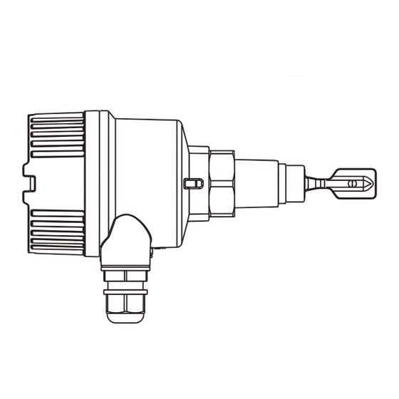
SC38 Multi-functional Tuning Fork Level Switch
(NPN/PNP Three-wire Type) Operation Manual
WORKING PRINCIPLE
The piezoelectric component is used to drive the tuning fork and feedback
signal, which produces the resonation on the fork. When the fork comes into
contact with a material, it relies on the damping effect by covering the testing
material on the tuning fork which changes the frequency of the tuning fork. The
frequency is judged by the micro-processor in the circuit. The signal display
and output status are determined based on the conditions set by the user.
SPECIFICATION
Power supply
10~55 Vdc
Power consumption
15mA
Input protection
Reverse protection function
OVP
Overvoltage category III
Max. measurement error
Max. ±1 mm
Repeatability
0.5mm
Hysteresis band
Approx. 2 mm
Storage temp.
-40~85°C
Environment temp.
-40~85°C
Operating temp.
-40~150°C
Material viscosity
2
Max. 10000 mm /s (10000 cst)
Particle size in liquid
Max. 5 mm
f
General cable
f6~10 mm
Operating pressure
Max. 40 Bar
Protection grade
IP 66/67
Contact capacity
350mA, 55Vdc
PANEL AND ELECTRICAL
F.S.
D.T.
S.G.
S. I.
Calibration Button
MAX
S
H
F .S.
MIN
L
L
O.S.
Test
SC38
U 10...55VDC
-
PWR
SIG
L-
O/P
PNP: L+
GND
NPN: L-
L+
O/P
Fuse
R
50mA
10~55 Vdc
R=External Load
U
max. 55Vdc@I
max. 350mA
L
FEATURES
All-in-one design, 3/4" thread is suitable to the installation of a small tube
(SC38 series).
A maximum length of 3m for the ultra-extension type.
Sensitivity adjustment is available for different density of media.
(ρ >0 . 5 g/cm or ρ >0 . 7 g/cm )
3
3
High/low failure safe mode, safe and reliable.
Self-diagnosis can detect the fork abrasion
Switch delay function
Alarm indicators based on failure status or output status selected according
to the customer's habits
Test button can be tested after the installation is completed
Calibration of the operation points for different density of media by the
customer if required
DIMENSIONS
(Unit:mm)
f84
107
1/2"PF
Hex38
3/4"PT
L
40
17
SC380
Common Type
120
75
SC380
SC381
SC382
High-Temperature Type
120
120
17.4
17.4
120
75
SC380
SC381
SC382
DESCRIPTION OF FEATURES
Abbr.
Function
Options description
Reverse the signal output
Test
Test Bottom
MAX: High
F.S.
Fail Safe
MIN: Low
S: Default setting
Delay Time
D.T.
L: Delay for 5 second
H: ³0.7 g/
Specific Gravity
S.G.
L:
³
0.5 g/
F.S.: Fail-Safe mode
S.I.
Signal Indicator
O.S.: Output mode
OUTPUT STATUS
SC38 provides Max./Min. operation modes, and has the corresponding
indicators and output status according to the functional settings and whether it
is covered by the material. The working status is detailed in the figure below.
Failure Mode
Material Level Output Signal
MAX
MIN
Instrument failure
Over Load(IL>350mA)
I : Load current
L
FORK TRIGGER POINT
The position of the SC38 fork trigger point depends on the mounting position
as shown in the figure below: (When the testing medium is water, S.G.=1
g/cm , temperature 23°C, and working pressure 0 Bar ). If the testing medium
3
120~3000
3
has an S.G lower than 1g/cm , the trigger point would rise. Similarly, the trigger
point will move downward while the S.G is larger than that of water. The
moving range is depended on the S.G
※Operating point position:
120
17.4
120~3000
Top Mounting
Notes
It is for the test after the installation is completed.
It is for the high and low Fail-Safe mode.
Covered by material: Approx. 0.5s
Not covered by material: Approx. 1.s
Switch to L to set it as 5 seconds for being covered or not covered by the material.
3
cm
The switch to set the material density.
3
cm
Turn ON/OFF the red indicator based on the output status or the fail-safe status.
DESCRIPTION OF TEST BUTTON
This button is mainly provided for the user to check whether the output
operation works normally after the installation is completed. When the button is
pressed, the output and indicator (ON<->OFF) will be reversed. Once the
button is released, it will recover the original status.
LED Indicator
FUNCTION OF SELF-SET OPERATING POINT POSITION
O.S.
I
L
F.S.
SC38 provides the function of customizing the operating point position in
accordance with what is required by the user.
O.S.
<100mA
F.S.
Calibration
Normal model
O.S.
I
L
F.S.
Settings
O.S.
1. Keep pressing the "Calibration Button" for 3 seconds. When the red and
<100 A
m
green LED indicators flash in turn every 0.5 second, it enters the calibration
F.S.
mode. Press the calibration button again to enter the Empty Bin Calibration
mode.
m
[Empty Bin Calibration]
<100 A
2. Calibration status: The red LED indicator flashes every 0.5 second, and the
output current switches to operate every 0.5 second.
3. This mode is to calibrate the vibration frequency of the tuning fork in the air.
<100 A
m
Thus, it shall press "Calibration Button" when the tuning fork doesn't sense
any material. In this case, it will write the vibration frequency in the air, and
enter the operating point calibration mode.
: Flash
: ON
: OFF
[Operating Point Calibration]
1. Calibration status: The red LED indicator flashes every 0.25 second, and the
output current switches to operate every 0.25 second.
2. Cover the material to the desired operating point position under this mode,
and then press "Calibration Button". It will be adjusted to the corresponding
operating point position according to the H/L setting of the S.G.
ENVIRONMENT/MEDIUM TEMPERATURE LIMITATION
T
a
T
p
13mm
: Temp. range for the common type
: Temp. range for the high-temp. type installed with the external
radiating pipe.
Empty
Operation point
model
calibration
bin calibration
T
a
85LC
(175LF)
50LC
T
p
-40LC
0LC
90LC
150LC
(-40LF)
(32LF)
(194LF)
(300LF)
-40LC
(
-40
LF)
Advertisement
Table of Contents

Related Manuals for FineTek SC38


Summary of Contents for FineTek SC38
- Page 1 F.S. D.T. S.G. S. I. The position of the SC38 fork trigger point depends on the mounting position and then press “Calibration Button”. It will be adjusted to the corresponding Calibration Button F .S. as shown in the figure below: (When the testing medium is water, S.G.=1 operating point position according to the H/L setting of the S.G.
- Page 2 PRODUCT APPLICATION 3. When installing the standard tuning fork, please make sure it is in flush 4. The protective tube should be installed when the liquid fluctuates The product can detect the high/low level of the medium in the tank or the tube, which is applicable to various liquids, such as in the food or pharmaceuticals with the sidewall.
Need help?
Do you have a question about the SC38 and is the answer not in the manual?
Questions and answers