GFA TS981 Installation Instructions Manual
Door control
Hide thumbs
Also See for TS981:
- Installation instructions manual (52 pages) ,
- Installation instructions manual (56 pages)
Table of Contents
Advertisement
Quick Links
Pos: null /Überarbeitung_Torsteuerungs-MAL/Deckblatt/Deckblatt_TS981_51002981_FT @ 91\mod_1683802862108_28.docx @ 1938234 @ @ 1
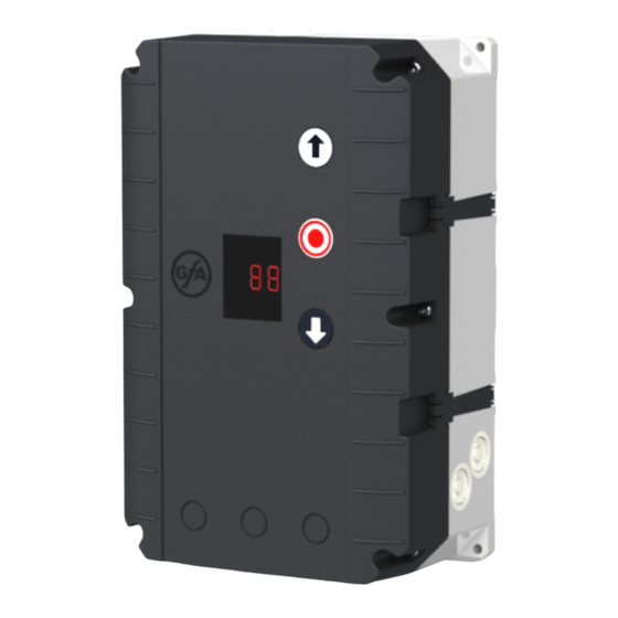
Installation Instructions
Door control ‐ TS981
Folding door control
0000000 0000 51002981 00002
Pos: null /BA_Module_Manuell/Allgemeine_Module/BA_Seitenumbruch @ 29\mod_1567592807787_0.docx @ 1515778 @ @ 1
‐en‐
51002981.00002
Status: a / 05.2023
Advertisement
Table of Contents

Related Manuals for GFA TS981


Summary of Contents for GFA TS981
- Page 1 Pos: null /Überarbeitung_Torsteuerungs-MAL/Deckblatt/Deckblatt_TS981_51002981_FT @ 91\mod_1683802862108_28.docx @ 1938234 @ @ 1 Installation Instructions Door control ‐ TS981 Folding door control ‐en‐ 51002981.00002 0000000 0000 51002981 00002 Status: a / 05.2023 Pos: null /BA_Module_Manuell/Allgemeine_Module/BA_Seitenumbruch @ 29\mod_1567592807787_0.docx @ 1515778 @ @ 1 ...
-
Page 2: Table Of Contents
Pos: null /Überarbeitung_Torsteuerungs-MAL/Inhaltsverzeichnis/TS_Inhaltsverzeichnis @ 72\mod_1648795042945_28.docx @ 1825644 @ @ 1 Table of contents 1 Safety‐relevant chapter .......................... 4 Explanation of symbols........................... 4 Intended use .............................. 4 Target audience of these installation instructions .................. 4 Safe operation .............................. 5 General safety instructions .......................... 5 2 Storage .............................. 5 3 Transport ............................... 5 4 Product overview ........................... 6 Technical data.............................. 6 ... - Page 3 Pos: null /Überarbeitung_Torsteuerungs-MAL/Adressen/Adresse_GfA-Deutschland @ 84\mod_1658911342715_28.docx @ 1879749 @ @ 1 Germany: UK: Australia: GfA ELEKTROMATEN GfA ELEKTROMATEN UK Ltd. GfA‐ELEKTROMATEN GmbH&Co.KG Agincourt Road Australia Pty Ltd Wiesenstraße 81 Warwick P.O. Box 267 40549 Düsseldorf CV34 6XZ Roseville 2069 NSW www.gfa‐elektromaten.de www.gfa‐elektromaten.co.uk www.gfa‐elektromaten.net info@gfa‐elektromaten.de ...
-
Page 4: Safety-Relevant Chapter
Note: Points out useful additional information. Pos: null /Überarbeitung_Torsteuerungs-MAL/Sicherheitskapitel/Bestimmungsgemäße Verwendung/Sicherheitskapitel_bestgemVerwendung_01_DESNES @ 67\mod_1624012964196_28.docx @ 1755848 @ 2 @ 1 Intended use The door control is intended for installation in a force‐actuated door with GfA limit switch system. Pos: null /Überarbeitung_Torsteuerungs-MAL/Sicherheitskapitel/Bestimmungsgemäße Verwendung/Sicherheitskapitel_bestgemVerwendung_03_allgemein_nichtATEX @ 67\mod_1624012669339_28.docx @ 1755827 @ @ 1 The drive unit must be protected against moisture and aggressive environmental conditions (such as corrosive substances). The drive units are only suitable for indoor use. Appropriate protective measures must be taken for outdoor installation. The drive unit is not intended for hazardous areas. The values specified in the technical data of the drive unit must not be exceeded. The safe operation can only be ensured if used as specified. ... -
Page 5: Safe Operation
Pos: null /Überarbeitung_Torsteuerungs-MAL/Sicherheitskapitel/Betriebssicherheit/Sicherheitskapitel_Betriebssicherheit @ 67\mod_1624014009761_28.docx @ 1755924 @ 2 @ 1 Safe operation The safe operation of the product can only be ensured if it is used as specified. Follow the installation instructions. Observe all specifications, especially warnings, when installing the product in the overall system. GfA is not liable for damage resulting from non‐observance of the installation instructions. The resulting overall system must be reassessed for its safety in accordance with applicable standards and directives (e.g. CE marking). These installation instructions refer only to a part of the overall system and are not sufficient as the sole instructions for the overall system. The installer of the system must prepare the instructions for the overall system. We recommend entering the danger area of the system only when the drive unit is at a standstill. Pos: null /Überarbeitung_Torsteuerungs-MAL/Sicherheitskapitel/Allgemeine Sicherheitshinweise/Sicherheitskapitel_AllgemeineSicherheitshinweise_EU_neuesLayout @ 67\mod_1624011340880_28.docx @ 1755784 @ 2 @ 1 General safety instructions WARNING ... -
Page 6: Product Overview
Pos: null /Überarbeitung_Torsteuerungs-MAL/Produktübersicht/Technische Daten/TS_mit Einträgen/TD_060_Steuereingänge_TS971 @ 84\mod_1658485672600_28.docx @ 1877269 @ @ 1 Control inputs 24 V DC, typ. 10 mA Pos: null /Überarbeitung_Torsteuerungs-MAL/Produktübersicht/Technische Daten/TS_mit Einträgen/TD_070_Kompatible GfA Endschalter_TS981 @ 92\mod_1692187687704_28.docx @ 1953984 @ @ 1 Compatible GfA ‐ limit switch Digital limit switch (DES) Pos: null /Überarbeitung_Torsteuerungs-MAL/Produktübersicht/Übersichtsdarstellung/Übersichtsdarstellung_TS981FT @ 87\mod_1671698805693_28.docx @ 1914415 @ 2 @ 1 ... -
Page 7: Overview Display Ts 981
Overview display TS 981 / SD DES Slot digital limit switch (DES) X 24 V mains supply, external devices F1 Micro‐fuse 1.6 A time‐lag X1 Mains supply MOT Motor socket X2 Safety edge OPEN and pass‐door plug MMC/SD Slot for memory cards X3 Emergency STOP control device SLF Slot for Air‐lock control function X5 Control device, external three push‐button SMF Slot for Status / Information function X6 Through / reflective photo cell S0 Slot built in push button X7 Pull switch, external radio receiver S1 Selector switch ... -
Page 8: Status Displays Of The Door Control
Status displays of the door control The display of the door control consists of a double‐ digit seven‐segment‐display. The display can show symbols, letters, or numbers. The figure shows the display when all segments are illuminated. i NOTE An E alternating with a number on the door control stands for a movement command. An F alternating with a number on the door control stands for a fault indication. See Chapter : Fault indication. Status display during initial operation These symbols appear only while the final limit positions are set. Display Description Changing output rotating direction is active. Changing output rotating direction is completed. Flashing: Teaching in final limit position OPEN. Flashing: Teaching in final limit position CLOSE. Pos: null /Überarbeitung_Torsteuerungs-MAL/Produktübersicht/Statusanzeigen der Torsteuerung/TS9xx_Produktübersicht_010_Statusanzeigen_AnzeigeTSbeiBetrieb_ohne8.8 @ 87\mod_1671528346096_28.docx @ 1913106 @ @ 1 ... -
Page 9: Mechanical Installation
Movement command display The movement commands appear on the display when the door control receives OPEN, CLOSE or STOP commands. Display Description Display alternates between E. and number: OPEN command received. STOP command received. CLOSE command received. Pos: null /Überarbeitung_Torsteuerungs-MAL/Mechanische Montage/TS9XX_MechanischeMontage_001_Überschrift+WHW @ 87\mod_1673427516529_28.docx @ 1916026 @ 1 @ 1 5 Mechanical installation NOTICE Damage to components due to extreme environmental conditions! Extreme environmental conditions (humidity, chemical substances) at the installation site may damage the product. Install the product indoors only. Installed outdoors, the product must be enclosed to provide the same conditions as in an indoor environment. Ensure that the installed connection cables are protected. Protect the product from moisture. Maintain the temperature range and the maximum humidity during operation. ... -
Page 10: Electrical Installation
Pos: null /Überarbeitung_Torsteuerungs-MAL/Elektrische Montage/Überschrift+allgemeine Warnhinweise/TS_ElekMontage_Überschrift + allgemeine Warnhinweise @ 71\mod_1639043235624_28.docx @ 1800534 @ 1 @ 1 6 Electrical installation WARNING Danger to life from electric shock! Improper wiring may result in severe or fatal injury from electrical current. Allow only qualified electricians to carry out the work. Disconnect all cables from the power supply. Secure the mains disconnector against plugging in or switching it on again. Observe valid regulations and standards. Use suitable tools. WARNING Mortal danger due to inadequate fuse! Without the correct on‐site backup fuse and mains disconnector, there is a risk of fatal or severe injury from electrical current. ... -
Page 11: Connecting Door Control And Drive Unit
Connecting door control and drive unit NOTICE Damage to the product due to work carried out improperly Use proper tools to prevent damage and leakage. 1. Remove the cover 2. Run the connection cable through the housing and insert the plugs. 3. Tighten the cable gland. NOTICE Damage due to moisture or penetrating foreign bodies Check that all cable glands are tight. Seal open and unused cable entries with blanking plugs. This will prevent moisture or foreign bodies such as insects from penetrating. Pos: null /Überarbeitung_Torsteuerungs-MAL/Elektrische Montage/TS an Netz anschließen/TS9XX_ElekMontage_NetzzuleitungAnschließen_TS-A @ 85\mod_1662544937731_28.docx @ 1888113 @ 2 @ 1 ... - Page 12 SI 25.15 WS, SI 45.7 WS 3‐phase with neutral 3‐phase without neutral 1‐phase symmetrical 1‐phase asymmetrical 3~, N, PE 3~, PE 1~, N, PE, sym. 1~, N, PE, asymmetrical 220–400 V / 50‐60 Hz 220–400 V / 50‐60 Hz 220– 230V / 50‐60 Hz 220–230 V / 50‐60 Hz NOTICE Damage due to moisture or penetrating foreign bodies Check that all cable glands are tight. Seal open and unused cable entries with blanking plugs. This will prevent moisture or foreign bodies such as insects from penetrating. Pos: null /BA_Module/BA_Seitenumbruch @ 0\mod_1190719383361_0.docx @ 550 @ @ 1 12 ...
-
Page 13: Connecting External Devices
Pos: null /Überarbeitung_Torsteuerungs-MAL/Externe Geräte anschließen/Überschrift_Externe Geräte anschließen @ 71\mod_1641817088857_28.docx @ 1804754 @ 1 @ 1 7 Connecting external devices WARNING Danger to life from electric shock! Improper wiring may result in severe or fatal injury from electrical current. Allow only qualified electricians to carry out the work. Disconnect all cables from the power supply. Secure the mains disconnector against plugging in or switching it on again. Observe valid regulations and standards. Use suitable tools. Check the insulation of cables and make sure that cables outdoors are protected. Pos: null /Überarbeitung_Torsteuerungs-MAL/Externe Geräte anschließen/Externe Geräte_Allg Sicherheitshinweise_Plc-Hinweise @ 88\mod_1676877522502_28.docx @ 1921704 @ @ 1 ... -
Page 14: X2 / X18 - Safety Edge System
X2 / X18 ‐ safety edge system The door control automatically recognises 3 different safety edge types. Terminals X2.1 ‐ X2.5 are provided for the safety edge system in the OPEN travel direction and the door safety switch. For the safety edge system in the CLOSE travel direction, a connection to X18 is provided for each door leaf. Various examples of safety edge systems are shown. Mount the product according to the manufacturer's instructions. Safety edge system in the OPEN travel direction Safety edge system with external evaluation The safety edge system has an output contact that is closed when there are no faults and the edge is not actuated. The 1k2 resistor is needed to detect any faults in the connection between the output contact and the door control input. Resistor evaluation 8k2 with NO contact principle This type of safety edge evaluation is intended for electrical safety edges with a termination resistor of 8k2, +/‐ 5% and 0.25W. The termination resistor must be connected to the end of the safety edge. Optical safety edge (example: Vitector system) The functional principle of the safety edge system is based on a through photocell. Actuating the safety edge interrupts the light beam. = transmitter = receiver 14 ... - Page 15 Safety edge system in the CLOSE travel direction Check the automatically set pre‐limit switch. If the door is open more than 5 cm, the door must reverse when the safety edge system is actuated. Both safety inputs on X18 must be assigned the same type of safety edge system. Safety edge system with external evaluation ‐ double Resistor evaluation 8k2 with NO contact principle ‐ double Optical safety edge ‐ double : Transmitter ‐ : Receiver i NOTE When automatic closing is set and the safety edge X18 is activated twice in a row, automatic closing is interrupted, and fault indication F 2.2 appears. Reset the fault by pressing the button on the housing. Pos: null /Überarbeitung_Torsteuerungs-MAL/Externe Geräte anschließen/X2/TS_ExterneGeräte_X2_020_Torsicherheitsschalter1_Schlaffseil-Schlupftür @ 85\mod_1661333854411_28.docx @ 1885830 @ 2 @ 1 ...
-
Page 16: X2 - Door Safety Switch
X2 ‐ Door safety switch You can connect a door safety switch for a pass door or slack‐rope switch to terminals X2.1/2.2. The door safety switches are connected to a safety circuit with Performance Level c (PLc) according to ISO 13849‐1. The safety circuit requires an overall terminal resistance of 5k0 for line cross‐circuit monitoring. Examples of door safety switches are shown below. Connect your product accordingly. Mount the product according to the manufacturer's instructions. i NOTE When activated while the door is moving, the door stops and fault indication F 1.2 appears. When the switch fails, fault indication F1.7 is displayed. In the case of a line cross‐circuit, fault indication F1.8 is displayed. Slack‐rope switch / electronic pass‐door switch The evaluation of the door control provides for the connection of two slack‐rope switches. Resistance for line cross‐circuit monitoring when using slack rope switches: 1k5 Resistance for line cross‐circuit monitoring when using electronic pass‐door switches: 2k0 A18 Connection socket ST+ Voltage supply (12 V) S30a ST Input for door safety switch S30a/b Slack‐rope switch (NC contact) S31 Electronic pass‐door switch S30b Pos: null /Überarbeitung_Torsteuerungs-MAL/Externe Geräte anschließen/X3/Externe Geräte_X3_Not-Halt @ 72\mod_1649318342837_28.docx @ 1827265 @ 2 @ 1 ... -
Page 17: X6/X16 - Photocell And Light Curtain
Install the product according to the manufacturer‘s instructions. Several examples of control devices are shown. WARNING Danger due to unattended door movement! The safety devices are deactivated in operating mode hold‐to‐run. People or objects in the movement path are not detected. Install and operate the control device only with a clear view of the door. X5 / X5 / X5 / Triple pushbutton Triple pushbutton with command interlock Key pushbutton i NOTE If you connect a control device without a STOP button to terminals X5, you need to install a jumper between X5.1/X5.2 or X15.1 to X15.2. Pos: null /Überarbeitung_Torsteuerungs-MAL/Externe Geräte anschließen/X6 (X16)/TS9XX_ExterneGeräte_001_X6-X16_Überschrift+Einleitung @ 87\mod_1673429679255_28.docx @ 1916364 @ 2 @ 1 ... - Page 18 Photocells A photocell is used for object protection and activated with operating modes 0.3 / 0.4. The photocell only switches in the final limit position OPEN and during CLOSE operation. X6 / X6 / X6 / 1 2 3 4 5 1 2 3 4 5 A8: Reflective photocell Through photocell Through photocell A9: Transmitter A11: Transmitter A10: Receiver A12: Receiver Pos: null /Überarbeitung_Torsteuerungs-MAL/Externe Geräte anschließen/X6 (X16)/TS9XX_ExterneGeräte_030_X6-X16_Hinweis-F21 @ 87\mod_1673430006472_28.docx @ 1916428 @ @ 1 ...
-
Page 19: X7 / X17 - Radio Receiver / Pull Switch
X7 / X17 ‐ Radio receiver / pull switch You can connect a pull switch or radio receiver to X7 / X7 / terminals X7.1/X7.2 and X17.1/X17.2. The switching contact must be potential‐free. Install the product according to the manufacturer‘s instructions. Activate the product after completion of the electrical installation with menu item 2.6. 1 2 3 4 Radio receiver Pull switch Pos: null /Überarbeitung_Torsteuerungs-MAL/Externe Geräte anschließen/X11/Externe Geräte_X11_Zeitschließung @ 85\mod_1662549842096_28.docx @ 1888305 @ 2 @ 1 ... -
Page 20: X20 / X21 - Relay Contacts For Traffic Lights, Light Curtains Or Magnetic Brakes
Pos: null /Überarbeitung_Torsteuerungs-MAL/Externe Geräte anschließen/X20/X21/TS9XX_ExterneGeräte_030_Hinweis-LED_Ampeln @ 87\mod_1673433193713_28.docx @ 1916753 @ @ 1 i NOTE We recommend the use of LED trafficlights with 230 V. Pos: null /Überarbeitung_Torsteuerungs-MAL/Externe Geräte anschließen/UBS/Externe Geräte_UBS @ 72\mod_1649920431137_28.docx @ 1829894 @ 2 @ 1 UBS‐Connection The UBS system is a simple pluggable connection technology from GfA. The control devices are connected to the control by a commercially available patch cable and detected automatically. UBS devices have the same functions as wired control devices Examples for UBS‐Connection ... -
Page 21: Air Lock (Slf)
Pos: null /Überarbeitung_Torsteuerungs-MAL/Externe Geräte anschließen/SLF/Externe Geräte_Schleusenfunktion (SLF) @ 85\mod_1662564276031_28.docx @ 1888484 @ 2 @ 1 Air lock (SLF) Air‐lock management could be realized by means an easy electrical cable connection between two shutters with TS 981. The required module with cable should be connected into SLF plug‐in. This module would be delivered complete within a manual. i NOTE When cable connection is finalized select “Air‐Lock on” in menu item 7.1 in both door controls. Automatic OPEN ‐ Transmission To realise Air‐lock operation a push button is not required. An automatic open impulse about timer adjustment could be selected in menu item 7.2, thereafter the present closed shutter opens when acting shutter has closed. Pos: null /Überarbeitung_Torsteuerungs-MAL/Externe Geräte anschließen/SMF/Externe Geräte_Statusmeldefunktion (SMF) @ 85\mod_1662564405851_28.docx @ 1888506 @ 2 @ 1 ... -
Page 22: Setting The Final Limit Positions
Pos: null /Überarbeitung_Torsteuerungs-MAL/Endlagen einstellen/00_Endlagen einstellen Überschrift + Einleitung + Info @ 72\mod_1642146177074_28.docx @ 1806234 @ 1 @ 1 8 Setting the final limit positions The following explains how to set the final limit positions of the door at the initial commissioning. i NOTE You can correct the final limit positions later with menu items P 1. 1 - P 1.4. Pos: null /Überarbeitung_Torsteuerungs-MAL/Endlagen einstellen/01_Endlagen einstellen_DES @ 72\mod_1649676458196_28.docx @ 1828613 @ @ 1 ... -
Page 23: Programming
Pos: null /Überarbeitung_Torsteuerungs-MAL/Programmieren/00 Programmieren/00_Programmieren @ 72\mod_1649256844273_28.docx @ 1827081 @ 12 @ 1 9 Programming i NOTE Before you can start programming, you must have set the final limit positions. Programming the door control 1. Start programming: Press the selector switch for 3 seconds. The display changes to 0.0. 2. Select the menu item: Turn the selector switch to the desired menu item. Press the selector switch once to confirm the selection. This will take you to the options. 3. Selecting options: ... -
Page 24: Menu Items
Pos: null /Überarbeitung_Torsteuerungs-MAL/Programmieren/0.1 Betriebsart/0.1 Betriebsart_Einleitung+WHW @ 68\mod_1627455695555_28.docx @ 1766185 @ 22 @ 1 Menu items: P 0.1 ‐ Operating mode With this menu item, you select the operating mode for moving the door during OPEN operation and CLOSE operation. When selecting the option, note the following: the number of safety devices and safety edges at the door. the optional connection of a command device to terminals X5. WARNING Danger due to unattended door movement! The safety devices are deactivated in operating mode hold‐to‐run. People or objects in the movement path are not detected. Operate the door only with a clear view of the door. Options .6, provide additional safety; the safety devices remain active despite operating mode hold‐to‐ run. Pos: null /Überarbeitung_Torsteuerungs-MAL/Programmieren/0.1 Betriebsart/0.1 Betriebsart_MP-01-02-04_TS981-FT @ 87\mod_1671634578984_28.docx @ 1914244 @ @ 1 ... -
Page 25: P 1.3 - 1.5 - Fine Correction Of Final Limit Positions
P 1.3 – 1.5 ‐ Fine correction of final limit positions Use this menu item to modify the final limit positions of the door that have been already set. No door movement takes place during fine correction. Proceed step by step. Fine correction of final limit position OPEN (DES) Fine correction of final limit position CLOSE (DES) Fine correction of the safety edge‘s pre‐limit (DES) Correction in direction of final limit position CLOSE Correction in direction of final limit position OPEN i NOTE Use menu item P 2.1 to activate or deactivate the safety edge in the pre‐limit area. Pos: null /Überarbeitung_Torsteuerungs-MAL/Programmieren/1.7-1.8 Schaltposition Relais X20/21/1.7-1.8 Schaltposition Relais X20/21 @ 68\mod_1627465011431_28.docx @ 1766426 @ 2 @ 1 P 1.7 / 1.8 ‐ Switching position of relays X20/X21 With this menu item you can set the door position in which relays X20 and X21 switch. To use this function, you must set menu item P 2.7/P 2.8 and connect a device to X20 and/or X21. ... -
Page 26: P 2.1 - Safety Edge In Pre-Limit Area
Pos: null /Überarbeitung_Torsteuerungs-MAL/Programmieren/2.1 Sicherheitsschaltleiste im Vorendschalterbereich/2.1_Sicherheitsschaltleiste im Vorendschalterbereich_Einleitung+WHW @ 84\mod_1658907010986_28.docx @ 1879604 @ 2 @ 1 P 2.1 ‐ Safety edge in pre‐limit area Use this menu item to activate or deactivate the safety edge in the pre‐limit area. Pos: null /Überarbeitung_Torsteuerungs-MAL/Programmieren/2.1 Sicherheitsschaltleiste im Vorendschalterbereich/2.1_Sicherheitsschaltleiste Vorendschalterbereich_MP_01-02-03-04 @ 68\mod_1627465644228_28.docx @ 1766468 @ @ 1 Function of the safety edge system in the pre‐limit area Safety edge active ► Safety edge is inactive (e.g. with a non‐contact photocell) Ground adjustment (DES) ... -
Page 27: P 2.3 - Automatic Closing
Pos: null /Überarbeitung_Torsteuerungs-MAL/Programmieren/2.3 Zeitschließung/TS9XX_Programmieren_23_001_Beschreibung-TS981 @ 85\mod_1663080367771_28.docx @ 1889603 @ 2 @ 1 P 2.3 ‐ Automatic closing With this menu item, you can select a time between 1 and 240 seconds after which the door closes automatically. You can connect a switch for activating and deactivating this function to terminals X11.1 and X11.2. The programmed time remains stored. Pos: null /Überarbeitung_Torsteuerungs-MAL/Programmieren/2.3 Zeitschließung/TS9XX_Programmieren_23_010_Tabelle+Hinweis @ 88\mod_1673441957406_28.docx @ 1916994 @ @ 1 Automatic closing Deactivated ► . 1 = 1 second up to 9.9 = 99 seconds .1 –2.40 ... -
Page 28: P 2.6 - Radio And Pull Switch Functions
Pos: null /Überarbeitung_Torsteuerungs-MAL/Programmieren/2.6 Funk- und Zugtasterfunktionen/2.6 Funk-Zugtaster_TS981 - ACHTUNG - Optionen anders als TS-B @ 85\mod_1663080696982_28.docx @ 1889625 @ 2 @ 1 P 2.6 ‐ Radio and pull switch functions First, connect a pull / radio switch to terminal X7 or X17. Use this menu item to determine how the door responds to a command from the radio or pull switch. Various types of impulses can be assigned. When the pull switch / radio receiver is activated once, the following door commands are executed depending on the door position or door movement. Type of impulse 1: command order without STOP Door position Door movement after activation Door in final limit position CLOSE Door moves to final limit position OPEN (with activated key switch in intermediate open) Door in OPEN movement No effect Door in final limit position OPEN Door moves to final limit position CLOSE ... -
Page 29: P 3.1 - Force Monitoring Of Sectional Doors
P 2.7/2.8 ‐ Relay functions of X20/ X21 Use menu item to control the function of X20. Use menu item to control the function of X21. Both menu items have the same options. Terminals X20 und X21 are potential‐free relay contacts. Relay functions of X20 Relay functions of X21 Deactivated Impulse of 1 second during OPEN operation at switching position. Switching position requires teach‐in with P 1.7/P 1.8. Permanent contact from switching position. Switching position requires teach‐in with P 1.7/P 1.8. Impulse of 1 second with OPEN command. Pos: null /Überarbeitung_Torsteuerungs-MAL/Programmieren/3.1 Kraftüberwachung Sektionaltore/3.1 Kraftüberwachung @ 68\mod_1627466821245_28.docx @ 1766666 @ 2 @ 1 P 3.1 ‐ Force monitoring of sectional doors Activate this menu item only if you operate a sectional door with counter‐balancing and digital limit switch (DES). Force monitoring detects whether the door also lifts people. Force monitoring is active from an opening width of approx. 0,05 m to 2 m. Slowly advancing changes, such as decreasing spring tension, are ... -
Page 30: P 4.1 - 4.9 - Frequency Inverter Functions
Pos: null /Überarbeitung_Torsteuerungs-MAL/Programmieren/4.1-4.9 FU-Funktionen/P-4.X_FU-Funktionen_Überschrift @ 87\mod_1671635221308_28.docx @ 1914308 @ 2 @ 1 P 4.1 – 4.9 ‐ Frequency inverter functions The following menu items are only visible and applicable if the door drive unit is equipped with a mounted frequency inverter. Pos: null /Überarbeitung_Torsteuerungs-MAL/Programmieren/4.1-4.9 FU-Funktionen/P-4.X_Tabelle_4.1-4.8 @ 87\mod_1671635275173_28.docx @ 1914330 @ @ 1 Increasing / decreasing the output speed Use this menu item to change the output speed of the door drive unit equipped with a frequency inverter. With menu item you can additionally increase the closing output speed from a height of 2.5 m onwards. To do this, you must first define the switching position for the higher output speed CLOSE with menu item . i NOTE The adjustable values ... -
Page 31: P 6.1 - Selecting The Traffic Control
With menu item , you increase/decrease the crawling speed in steps. The door drive unit moves at the crawling speed shortly before reaching the final limit position to precisely approach the cut‐off point of the final limit position. Increasing/decreasing crawling speed OPEN and CLOSE Possible values depend on the door drive unit. Pos: null /Überarbeitung_Torsteuerungs-MAL/Programmieren/6.1 Auswahl Verkehrsregelung/6.1 Auswahl Verkehrsregelung @ 68\mod_1627467400710_28.docx @ 1766813 @ 2 @ 1 P 6.1 ‐ Selecting the traffic control The traffic light control can be operated in two traffic control modes. Dual‐lane traffic The dual‐lane option is used when the door passage is wide enough for two vehicles to pass through the door in opposite directions at the same time. The traffic light indicates when the door is fully open. The traffic lights also indicate an imminent door movement in the CLOSE direction. Single‐lane traffic (with oncoming traffic) The option "single lane traffic (with oncoming traffic)" is used when the door passage is only wide enough for one vehicle and it is necessary to regulate which side has right of way. Selecting the traffic control Off ‐ the traffic lights are switched off ... -
Page 32: P 6.3 - Advance Warning Time
Red lights outside are on Red lights inside and outside are on Pos: null /Überarbeitung_Torsteuerungs-MAL/Programmieren/7.1 Schleusenfunktion/7.1 Schleusenfunktion @ 68\mod_1627471369212_28.docx @ 1766928 @ 2 @ 1 P 7.1 ‐ Interlock function An interlock can be operated with 2 identical door controls that are connected electrically. For the electrical connection, connect two junction boxes to the SLF socket using a plug. The junction boxes can be purchased from GfA as a set with the associated documentation. After wiring, activate menu item 7.1 for both door controls. Interlock function Off ► On Pos: null /Überarbeitung_Torsteuerungs-MAL/Programmieren/7.2 AUF-Befehl Weiterschal. bei Schleuse ein/7.2 Weiterschaltung Schleuse @ 68\mod_1627471464750_28.docx @ 1766949 @ 2 @ 1 ... -
Page 33: P 7.2 - Open Relaying
Pos: null /Überarbeitung_Torsteuerungs-MAL/Programmieren/7.5 Auswahl Status-Meldefunktion SMF/7.5 Auswahl Status-Meldefunktion SMF @ 68\mod_1627471602936_28.docx @ 1766970 @ 2 @ 1 P 7.5 ‐ Status reporting function You can only use this menu item when a status reporting module is connected to the SMF interface. Status reporting function Off. Status reporting function for the GfA reporting module Status reporting function for interface module with unidirectional RS 232. Pos: null /Überarbeitung_Torsteuerungs-MAL/Programmieren/8.5 Wartungszykluszähler einstellen/8.5 Wartungszykluszähler einstellen @ 68\mod_1627472271222_28.docx @ 1767033 @ 2 @ 1 P 8.5 ‐ Setting the maintenance cycle counter With these menu items, you set a reminder for the maintenance of the door. The maintenance cycle can be ... -
Page 34: P 8.6 - Response After Expiry Of The Maintenance Cycle Counter
P 8.6 ‐ Response after expiry of the maintenance cycle counter Response after expiry of the maintenance cycle counter Display shows C.S alternating with the value specified in 8.5 ► Operating mode change to hold‐to‐run. Display shows C.S. alternating with the value specified in 8.5. Operating mode change to hold‐to‐run. Display shows C.S. alternating with the value specified in 8.5. Option: Press the STOP button for 3 seconds to ignore the message for 500 cycles. Display shows C.S. alternating with the value specified in 8.5. Relay contact X21 switches. i NOTE You can delete the response from menu item 8.6 by setting a new value with menu item 8.5. Pos: null /Überarbeitung_Torsteuerungs-MAL/Programmieren/9.1 Zykluszähler auslesen/9.1 Zykluszähler auslesen @ 68\mod_1627473526428_28.docx @ 1767054 @ 2 @ 1 P 9.1 ‐ Readout of cycle counter With this menu item, you can read out the cycle counter of the door control. The counter increases by 1 every time the door reaches the final limit position OPEN. It is not possible to reset the cycle counter. ... -
Page 35: P 9.2 - Readout Of Fault Indications
Pos: null /Überarbeitung_Torsteuerungs-MAL/Programmieren/9.4 Software-Version auslesen/9.4 Software-Version auslesen @ 68\mod_1627541576898_28.docx @ 1767265 @ 2 @ 1 P 9.4 ‐ Readout software version This menu item displays the software version of the door control. For drive units with GfA frequency inverter, the software version of the motor is shown as well. Readout software version The display changes and shows the number of the software version. Pos: null /Überarbeitung_Torsteuerungs-MAL/Programmieren/9.5 Auf Werkseinstellung zurücksetzen/ GfA-Stick nutzen/9.5 Auf Werkseinstellungen zurücksetzen_TS981 @ 91\mod_1690377294485_28.docx @ 1949374 @ 2 @ 1 35 ... -
Page 36: P 9.5 - Reset To Factory Settings
P 9.5 ‐ Reset to factory settings With option . 1, you delete all set menu items and reset the door control to factory setting. Reset to factory settings Reset to factory settings. Press the OPEN button once to select menu item . 1. Confirm your selection by pressing the STOP button for 3 seconds. Pos: null /Überarbeitung_Torsteuerungs-MAL/Programmieren/9.7 Software laden/9.7 Software laden @ 68\mod_1627543794583_28.docx @ 1767328 @ 2 @ 1 P 9.7 ‐ Loading Software Software can be loaded from a memory card in the MMC/SD slot with menu item 9.7. When selecting the menu item, software version 0 appears on the display. All software versions on the memory card can be displayed by pressing the OPEN and CLOSE push‐buttons. Load the software by pressing the STOP push‐button for 3 seconds. Press the selector switch to exit the menu item without loading any software. Loading software Select the software version on the card by turning, e.g., 1.1. ... -
Page 37: 10 Fault Correction
Pos: null /Überarbeitung_Torsteuerungs-MAL/Warten und Reparieren/Fehlermeldungen/0.0_Überschrift + Info @ 72\mod_1642158916091_28.docx @ 1806523 @ 1 @ 1 10 Fault correction i NOTE You can find detailed information on faults and how to rectify them in our fault guide for door controls. Download the fault guide from the GfA‐Portal. Start the fault guide using the GfA+ app. Pos: null /Überarbeitung_Torsteuerungs-MAL/Warten und Reparieren/Fehlermeldungen/0.1_Fehler-Torsteuerung-Aus_0.0 @ 72\mod_1649840407580_28.docx @ 1829208 @ 2 @ 1 Fault indications ... - Page 38 Pos: null /Überarbeitung_Torsteuerungs-MAL/Warten und Reparieren/Fehlermeldungen/Fehlermeldungen Kopfzeile @ 91\mod_1685603952592_28.docx @ 1939804 @ @ 1 Cause of the fault Fault correction Display alternates between F and number Pos: null /Überarbeitung_Torsteuerungs-MAL/Warten und Reparieren/Fehlermeldungen/1.3_Fehler-Sicherheitskette_1.3-1.4 @ 90\mod_1682667717784_28.docx @ 1936116 @ @ 1 Check the door drive unit for overload or stalling WARNING! Danger of the door dropping! Safety circuit is open. Do not release stalling when using a door drive unit with a safety brake! Stalling may indicate a catch incident. Replace Emergency manual operation is ...
- Page 39 Pos: null /Überarbeitung_Torsteuerungs-MAL/Warten und Reparieren/Fehlermeldungen/2.0_Fehler-Sicherheitseinrichtungen_2.0-2.1-2.2x @ 90\mod_1682667726652_28.docx @ 1936221 @ @ 1 Faults of safety devices Cause of the fault Fault correction Display alternates between F and number Check the wiring and condition of the safety edge. No safety edge detected. Check the DIP switch position in the door leaf box. Check the condition of the safety edge visually and electrically. Check the condition and alignment of the photocell. Remove obstacles from door area. Photocell activated. 2. 1 Clean the photocell and the reflector. Check the connection cable for breaks. Replace photocell if necessary. Remove obstacles from door area. ...
- Page 40 Pos: null /Überarbeitung_Torsteuerungs-MAL/Warten und Reparieren/Fehlermeldungen/3.0_Fehler-Endschalter_0Überschrift @ 90\mod_1682667736117_28.docx @ 1936326 @ @ 1 Fault at limit switch Cause of the fault Fault correction Display alternates between F and number Pos: null /Überarbeitung_Torsteuerungs-MAL/Warten und Reparieren/Fehlermeldungen/3.0_Fehler-Endschalter_3.0 @ 90\mod_1682667737821_28.docx @ 1936347 @ @ 1 No door position is set. Teach‐in the door positions again. Reset if necessary. Pos: null /Überarbeitung_Torsteuerungs-MAL/Warten und Reparieren/Fehlermeldungen/3.1_Fehler-Endschalter_3.1 @ 90\mod_1682667739536_28.docx @ 1936368 @ @ 1 ...
- Page 41 Pos: null /Überarbeitung_Torsteuerungs-MAL/Warten und Reparieren/Fehlermeldungen/4.0_Fehler-Sicherheitseinrichtungen_0Überschrift @ 91\mod_1688649231085_28.docx @ 1945508 @ @ 1 Faults of safety devices Cause of the fault Fault correction Display alternates between F and number Pos: null /Überarbeitung_Torsteuerungs-MAL/Warten und Reparieren/Fehlermeldungen/4.0_Fehler-Sicherheitseinrichtungen_4.0 @ 91\mod_1688648264114_28.docx @ 1945445 @ @ 1 Check the wiring and condition of the safety edge. No safety edge detected on X2 Check the condition of the safety edge visually and electrically. Check the operating mode setting. Pos: null /Überarbeitung_Torsteuerungs-MAL/Warten und Reparieren/Fehlermeldungen/4.1_Fehler-Intern_4.1 @ 90\mod_1682667755282_28.docx @ 1936536 @ @ 1 ...
- Page 42 Fault of door movement Cause of the fault Fault correction Display alternates between F and number Check the limit switch plug for firm seating. Check the connection cable visually for damage. Fault of digital limit switch (DES). Check the limit switch by replacing it with a properly functioning DES. Check door drive unit for stalling. WARNING! Danger of the door dropping! Fault in door movement. Do not release stalling when using a door drive unit with a The door mechanism is stiff or safety brake! Stalling may indicate a catch incident. Replace blocked. the door drive unit. Check the door mechanism for damage. The final limit position OPEN/CLOSE Check final limit position OPEN/CLOSE. When the door hits a is not reached. cushion, then correct the final limit position. Check the mains supply of the door control. Establish the A supply phase is missing. correct power supply. Brake does not release. Check the brake and rectifier. The limit switch is not driven. Check the limit switch turn while the door is moving. The running time is set incorrectly. Check and correct the voltage supply of the door control. Correct the running time (menu item 3.3) ...
- Page 43 Fault on the frequency converter These fault indications appear only for door drive units with a frequency inverter. Cause of the fault Fault correction Display alternates between F and number Check the door mechanism for stiffness. Only for doors with counter‐balancing: check for spring The closing speed is too high. fracture. Replace door drive unit if necessary. Switch the door control off and on. Internal communication fault of Check connection cable to limit switch. frequency inverter. Check the connection cable and the plug for firm seating. Replace door drive unit if necessary. Measure the voltage during door movement. Low voltage in the DC voltage link. Check mains supply. Change ramp times / speeds. (P 4.1‐P 4.9) Measure the voltage during door movement. Excess voltage in DC voltage link. Check mains supply. Change ramp times / speeds. (P 4.1‐P 4.9) Door drive unit overloaded. Temperature limit exceeded. Check for excessive ambient temperature. Allow door drive unit to cool and reduce number of cycles. Door drive unit overloaded. Permanent current overload. Check the door mechanism for stiffness. Pos: null /Überarbeitung_Torsteuerungs-MAL/Warten und Reparieren/Fehlermeldungen/6.9_Fehler am Frequenzumrichter_6.9 @ 91\mod_1682667774631_28.docx @ 1936746 @ @ 1 ...
- Page 44 Pos: null /Überarbeitung_Torsteuerungs-MAL/Warten und Reparieren/Wartung/Wartung_TS_DUMMY @ 72\mod_1649076809549_28.docx @ 1826357 @ 1 @ 1 11 Maintenance WARNING Danger to life from electric shock! Improper maintenance may result in fatal injury from electrical current. Disconnect all cables from the power supply. Only allow competent personnel or electricians to carry out the maintenance. Secure the mains disconnector against being switched on or plugged in again. The electronic components of the door control are maintenance‐free. Carry out the following maintenance operations at least once a year: Component Procedure Housing Use a dry cloth to remove dust and light dirt. Connecting cables Check the connecting cables for firm seating and possible damage (e.g. to the insulation). Replace damaged cables. Fasteners Check the fasteners for firm seating and damage. Replace damaged parts. ...
-
Page 45: Service Life
Pos: null /Überarbeitung_Torsteuerungs-MAL/Warten und Reparieren/Wartung/TS981_Wartung_Lebensdauer @ 86\mod_1669219510602_28.docx @ 1905077 @ 2 @ 1 Service life The door control has electromechanical power switches that are subject to wear. The wear depends on the number of door cycles and the switched power of ELEKTROMATEN. We recommend replacing the door control after the corresponding number of door cycles has been reached. The diagram below shows the relationship between the number of door cycles and the switched power of ELEKTROMATEN. 3 ~ 230 / 400 V 50 Hz 1 ~ 230 50 Hz Pos: null /BA_Module/BA_Seitenumbruch @ 0\mod_1190719383361_0.docx @ 550 @ @ 1 ... - Page 46 Pos: null /Überarbeitung_ELEKTROMATEN-MAL/BA_WA/Module/BAWA_050_Entsorgen/BAWA_50_Entsorgen_ELEKTROMATEN @ 88\mod_1676476167918_28.docx @ 1921126 @ 1 @ 1 12 Disposal Dispose of packaging Dispose of the packaging material properly according to the local legal regulations or recycle it. Dispose of old devices Dispose of old devices properly according to local legal regulations. Return old devices to the return and collection systems available. You can also return GfA products free of charge. Please apply enough postage to the package and mark it as "old devices". Pos: null /Überarbeitung_ELEKTROMATEN-MAL/BA_WA/Module/BAWA_050_Entsorgen/BAWA_52_Mülltonne @ 84\mod_1657787460638_28.docx @ 1875029 @ @ 1 i NOTE Old devices marked with the adjacent symbol must not be disposed of with unsorted municipal waste. ...
- Page 47 We, The following requirements from Appendix I of the GfA ELEKTROMATEN GmbH & Co. KG Supply Machinery (Safety) Regulations 2008 are met: declare under our sole responsibility that the 1.1.2, 1.1.3, 1.1.5, 1.2.2, 1.2.3, 1.2.6, 1.3.2, 1.3.3, following product complies with the above directives 1.3.9, 1.5.1, 1.5.2, 1.5.4, 1.5.6, 1.5.7, 1.5.8, 1.5.9, and is only intended for installation in a door system. 1.5.10, 1.5.11, 1.5.13, 1.6.1, 1.6.2, 1.6.4, 1.7.2, 1.7.3, 1.7.4.3. Door control TS981 Applied Standards: BS EN 12453:2022 We undertake to transmit in response to a reasoned Industrial, commercial and garage doors and gates ‐ request by the appropriate regulatory authorities the Safety in use of power operated doors ‐ special documents on the partly completed Requirements machinery. BS EN 12978:2003+A1:2009 This product must only be put into operation when it Industrial, commercial and garage doors and has been determined that the complete gates ‐ Safety devices for power operated doors machine/system in which it has been installed and gates ‐ Requirements and test methods ...
- Page 48 Pos: null /Überarbeitung_Torsteuerungs-MAL/Konformitätserklärung-EU/DoC-EU_Torsteuerung-TS981_MRL-EMV-ROHS @ 90\mod_1682426484272_28.docx @ 1932178 @ @ 1 Declaration of incorporation / Declaration of conformity Declaration of incorporation within the meaning of Machinery Directive 2006/42/EC for partly completed machinery, Appendix II Part B Declaration of conformity within the meaning of EMC Directive 2014/30/EU within the meaning of RoHS Directive 2011/65/EU We, The following requirements from Appendix I of GfA ELEKTROMATEN GmbH & Co. KG the Machinery Directive 2006/42/EC are met: 1.1.2, 1.1.3, 1.1.5, 1.2.1, 1.2.2, 1.2.3, 1.2.4.2, declare under our sole responsibility that the 1.2.5, 1.2.6, 1.3.1, 1.3.2, 1.3.3, 1.3.4, 1.3.9, following product complies with the above 1.5.1, 1.5.2, 1.5.4, 1.5.5, 1.5.6, 1.5.7, 1.5.8, directives and is only intended for installation in a 1.5.9, 1.5.10, 1.5.11, 1.5.13, 1.6.1, 1.6.2, 1.6.4, door system. 1.7.1.1, 1.7.1.2, 1.7.2, 1.7.3, 1.7.4.3. Door control TS 981 Standards applied: ...
Need help?
Do you have a question about the TS981 and is the answer not in the manual?
Questions and answers