GFA TS981 Installation Instructions Manual
Door control
Hide thumbs
Also See for TS981:
- Installation instructions manual (52 pages) ,
- Installation instructions manual (48 pages)

Related Manuals for GFA TS981


Summary of Contents for GFA TS981
- Page 1 Installation Instructions Door control - TS981 -en- 51000981.00002 Status: a / 05.2023 0000000 0000 51000981 00002...
-
Page 2: Table Of Contents
Table of contents Safety-relevant chapter ........................4 Explanation of symbols ...........................4 Intended use ..............................4 Target audience of these installation instructions ..................4 Safe operation ..............................5 General safety instructions ..........................5 Storage ............................... 5 Transport ............................5 Product overview ..........................6 Technical data ..............................6 Overview display TS 981 ..........................7 Status displays of the door control .........................8 Mechanical installation ........................ - Page 3 P 9.3 - Readout of the cycle counter since last programming change ............43 P 9.4 - Readout software version ........................43 P 9.5 - Reset to factory settings / use of GfA-Stick..................44 P 9.7 - Loading Software ..........................44 P 9.8 - Saving the software ..........................
-
Page 4: Safety-Relevant Chapter
Note: Points out useful additional information. Intended use The door control is intended for installation in a force-actuated door with GfA limit switch system. The drive unit must be protected against moisture and aggressive environmental conditions (such as corrosive substances). The drive units are only suitable for indoor use. Appropriate protective measures must be taken for outdoor installation. -
Page 5: Safe Operation
Observe all specifications, especially warnings, when installing the product in the overall system. GfA is not liable for damage resulting from non-observance of the installation instructions. The resulting overall system must be reassessed for its safety in accordance with applicable standards and directives (e.g. CE marking). -
Page 6: Product Overview
2 potential-free changeover Loading of relay contacts, ohmic 230 V AC, 1 A 24 V DC, 0,4 A inductive Control inputs 24 V DC, typ. 10 mA Compatible GfA - limit switch Mechanical limit switch (NES) Digital limit switch (DES) -
Page 7: Overview Display Ts 981
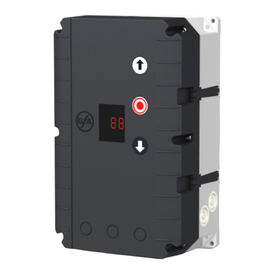
Overview display TS 981 / SD Slot digital limit switch (DES) 24 V mains supply, external devices Micro-fuse 1.6 A time-lag Mains supply Motor socket Door safety switch and safety devices MMC/SD Slot for memory cards Emergency STOP control device Slot for Air-lock control function Control device, external three push-button Slot for Status / Information function... -
Page 8: Status Displays Of The Door Control
Status displays of the door control The display of the door control consists of a double- digit seven-segment-display. The display can show symbols, letters, or numbers. The figure shows the display when all segments are illuminated. i NOTE An E alternating with a number on the door control stands for a movement command. An F alternating with a number on the door control stands for a fault indication. -
Page 9: Mechanical Installation
Movement command display The movement commands appear on the display when the door control receives OPEN, CLOSE or STOP commands. Display Description Display alternates between E. and number: OPEN command received. STOP command received. CLOSE command received. 5 Mechanical installation NOTICE Damage to components due to extreme environmental conditions! Extreme environmental conditions (humidity, chemical substances) at the installation site may damage the... -
Page 10: Electrical Installation
6 Electrical installation WARNING Danger to life from electric shock! Improper wiring may result in severe or fatal injury from electrical current. Allow only qualified electricians to carry out the work. Disconnect all cables from the power supply. ... -
Page 11: Connecting Door Control And Drive Unit
Connecting door control and drive unit NOTICE Damage to the product due to work carried out improperly Use proper tools to prevent damage and leakage. 1. Remove the cover 2. Run the connection cable through the housing and insert the plugs. 3. -
Page 12: Connecting External Devices
SI 25.15 WS, SI 45.7 WS 3-phase with neutral 3-phase without neutral 1-phase symmetrical 1-phase asymmetrical 3~, N, PE 3~, PE 1~, N, PE, sym. 1~, N, PE, asymmetrical 220–400 V / 50-60 Hz 220–400 V / 50-60 Hz 220– 230V / 50-60 Hz 220–230 V / 50-60 Hz NOTICE Damage due to moisture or penetrating foreign bodies... -
Page 13: X1 - Mains Supply / Supply Of External Devices
X1 - Mains supply / supply of external devices Mains supply of the door control. Note the chapter "Electrical installation / mains supply". i NOTE Supply of external devices External devices can only be supplied with power over terminals X1/1.8 and X1/1.9 when the door control is connected symmetrically to supply networks with 3 N~ 400 V or 1 N~ 230 V. -
Page 14: X2 - Door Safety Switch
Pneumatic safety edge The input is designed for a pressure-wave switch system (NC) with a terminal resistance of 1k2 (+/-5 % and 0.25 W). The pressure wave switch system needs to be tested with final limit position CLOSE. The test phase is initiated by pre-limit switch S5 (automatically for DES). If no switching signal is generated at the pressure wave switch within 2 seconds, the test is negative and fault indication F 2.8 appears. - Page 15 Slack-rope switch / electronic pass-door switch The evaluation of the door control provides for the connection of two slack-rope switches. Resistance for line cross-circuit monitoring when using slack rope switches: 1k5 Resistance for line cross-circuit monitoring when using electronic pass-door switches: 2k0 Connection socket Voltage supply (12 V) S30a...
-
Page 16: X3 - Emergency Stop
X3 - Emergency Stop The emergency STOP control device is connected to a safety circuit with Performance Level c (Plc) according to ISO 13849-1. Alternativly you can connect an emergency STOP control device as per EN 13850 or an evaluation unit for an anti-trap safety device. -
Page 17: X6/X16 - Photocell And Light Curtain
X6/X16 - Photocell and light curtain You can connect a light curtain or a reflective or through beam photocell to terminals X6.1/X6.2 and X16.1/X16.2 as well as 24V and GND. Mount the product according to the manufacturer's instructions. Various examples of photocells and light curtains are shown. Connect your product accordingly. ... -
Page 18: X7 / X17 - Radio Receiver / Pull Switch
Light curtain only with relay or semiconductor output The light curtain must be self-testing and correspond at least to safety category 2 or performance level c (plc). If the light curtain corresponds to these requirements, the door can close into self-hold without safety edge system. -
Page 19: X8 - Switch For Intermediate Open
X8 - Switch for intermediate open You can connect a switch for intermediate open of the door to terminals X8.1/X8.2. The switch activates this function. With an OPEN command, the door moves to the saved door position. Only when you deactivate this function with the switch, the door will return to the final limit position OPEN. ... -
Page 20: X12 - Signal Contact For Smoke And Heat Extraction
- Signal contact for smoke and heat extraction The signal contact of a fire alarm system can be connected to terminals X12.1 and X12.2. This allows the door to be used as a smoke and heat exhaust (SHE) in areas of up to 1600 m² (according to the Industrial Building Directive). -
Page 21: X18 - Safety Device Against Entrapment
X18 - Safety device against entrapment Two safety devices can be connected to terminals X18.1/X18.2 to prevent drawing in people. Mount the product according to the manufacturer's instructions. Shown are examples of safety devices against entrapment. Use menu item 3.7 to activate the product. You can also choose whether one or two inputs are active and which type is used: Evaluation principle Application... - Page 22 double Safety device against entrapment with impulse signal 1 kHz (e.g., Safety device against entrapment with impulse signal 1 kHz (e.g., Raytector) - single Raytector) - double Ⓐ: Transmitter - Ⓐ: Receiver Ⓐ: Transmitter - Ⓐ: Receiver 1 2 3 4 5 1 2 3 4 5 1 2 3 4 5 Through photocell as safety device against entrapment according to...
-
Page 23: X20 / X21 - Relay Contacts For Traffic Lights, Light Curtains Or Magnetic Brakes
We recommend the use of LED trafficlights with 230 V. UBS-Connection The UBS system is a simple pluggable connection technology from GfA. The control devices are connected to the control by a commercially available patch cable and detected automatically. UBS devices have the same functions as wired control devices... -
Page 24: Air Lock (Slf)
Air lock (SLF) Air-lock management could be realized by means an easy electrical cable connection between two shutters with TS 981. The required module with cable should be connected into SLF plug-in. This module would be delivered complete within a manual. i NOTE When cable connection is finalized select “Air-Lock on”... -
Page 25: Setting The Final Limit Positions
8 Setting the final limit positions The following explains how to set the final limit positions of the door at the initial commissioning. i NOTE You can correct the final limit positions later with menu items P 1. 1 - P 1.4. Setting the final limit positions - DES (digital limit switch) If you have already connected a safety edge, the pre-limit is automatically set with the final limit positions. -
Page 26: Programming
9 Programming i NOTE Before you can start programming, you must have set the final limit positions. Programming the door control 1. Start programming: Press the selector switch for 3 seconds. The display changes to 0.0. 2. Select the menu item: ... -
Page 27: Menu Items
Menu items: P 0.1 - Operating mode With this menu item, you select the operating mode for moving the door during OPEN operation and CLOSE operation. When selecting the option, note the following: ▪ the number of safety devices and safety edges at the door. ▪... -
Page 28: P 1.1 / 1.2 - Coarse Correction Of Final Limit Position
P 1.1 / 1.2 - Coarse correction of final limit position Use these menu items to modify the final limit positions of the door that have been already set. Coarse correction of final limit position OPEN (DES) Coarse correction of final limit position CLOSE (DES) ... -
Page 29: P 1.6 - Door Positions For Intermediate Open
P 1.6 - Door positions for intermediate open Use this menu item to set the door position for intermediate open. Intermediate open is a door position between final limit positions OPEN and CLOSE. This requires the connection of an external switch to the two terminals of connector X8. -
Page 30: P 2.1 - Safety Edge In Pre-Limit Area
P 2.1 - Safety edge in pre-limit area Use this menu item to activate or deactivate the safety edge in the pre-limit area. Function of the safety edge system in the pre-limit area Safety edge active ► Safety edge is inactive (e.g. with a non-contact photocell) Ground adjustment (DES) Reversing in overrun area (DES) Ground adjustment... -
Page 31: P 2.3 - Automatic Closing
P 2.3 - Automatic closing With this menu item, you can select a time between 1 and 240 seconds after which the door closes automatically. You can connect a switch for activating and deactivating this function to terminals X11.1 and X11.2. -
Page 32: P 2.5 - Limiting Reversals
P 2.5 - Limiting reversals Activate this menu item only if automatic closing 2.3 is enabled. When automatic closing is enabled, the door moves to final limit position CLOSED after the set time. The door reverses when hitting an obstacle during movement. -
Page 33: P 2.6 - Radio And Pull Switch Functions
P 2.6 - Radio and pull switch functions First, connect a pull / radio switch to terminal X7 or X17. Use this menu item to determine how the door responds to a command from the radio or pull switch. Various types of impulses can be assigned. -
Page 34: P 2.7/2.8 - Relay Functions Of X20/ X21
P 2.7/2.8 - Relay functions of X20/ X21 With menu item P 2.7, you control the function of X20 and with P 2.8 the function of X21. Both menu items have the same options. Terminals X20/X21 are potential-free relay contacts. Relay function on X20 Relay function on X21 Off. -
Page 35: P 3.1 - Force Monitoring Of Sectional Doors
P 3.1 - Force monitoring of sectional doors Activate this menu item only if you operate a sectional door with counter-balancing and digital limit switch (DES). Force monitoring detects whether the door also lifts people. Force monitoring is active from an opening width of approx. -
Page 36: P 3.2 - Interruption Of The Photocell
P 3.2 - Interruption of the photocell The function is only available für door drive units with digital limit switch (DES). Components on the door (e.g. spiral cables) may interrupt the photocell always in the same position. A fault indication appears. Use this menu item for setting the position. During CLOSE operation, the photocell will be deactivated from this position onwards. -
Page 37: P 3.5 - Automatic Opening
P 3.5 - Automatic opening The closed door opens after the set number of minutes. Use menu item 2.3 to set the automatic closing. Automatic opening ► 1 to 99 minutes P 3.8 - Shorten/lengthen the reversing time Use this menu item to shorten or lengthen the reversing time when a safety device is activated. Reversing time is the time it takes for the door to switch from CLOSE operation to OPEN operation. - Page 38 Setting the reference position for increased output speed CLOSE Move to the desired door position using the OPEN or CLOSE button. The position must be at a height at least 2,5 m. Save the door position by pressing the STOP button once. Acceleration to output speed OPEN/CLOSE With menu items 4.5 and 4.6, you increase/decrease the time required by the door drive unit for accelerating to the specified output speed (4.1 - 4.3).
-
Page 39: P 6.1 - Auswahl Verkehrsregelung
P 6.1 - Auswahl Verkehrsregelung Die Ampelsteuerung kann in zwei Verkehrsregelungsarten betrieben werden. Einbahnverkehr Die Einbahnverkehr-Option wird verwendet, wenn die Tordurchfahrt so breit ist, dass zwei Fahrzeuge gleichzeitig das Tor durchfahren können. Die Ampel zeigt an, wann das Tor vollständig geöffnet ist. Zusätzlich zeigen die Ampeln eine bevorstehende Torbewegung in ZU-Richtung an. -
Page 40: P 6.4 - Clearing Time
For the electrical connection, connect two junction boxes to the SLF socket using a plug. The junction boxes can be purchased from GfA as a set with the associated documentation. After wiring, activate menu item 7.1 for both door controls. -
Page 41: P 7.2 - Open Relaying
You can only use this menu item when a status reporting module is connected to the SMF interface. Status reporting function Off. Status reporting function for the GfA reporting module Status reporting function for interface module with unidirectional RS 232. P 8.5 - Setting the maintenance cycle counter With these menu items, you set a reminder for the maintenance of the door. -
Page 42: P 8.6 - Response After Expiry Of The Maintenance Cycle Counter
P 8.6 - Response after expiry of the maintenance cycle counter Response after expiry of the maintenance cycle counter Display shows C.S alternating with the value specified in 8.5 ► Operating mode change to hold-to-run. Display shows C.S. alternating with the value specified in 8.5. Operating mode change to hold-to-run. -
Page 43: P 9.2 - Readout Of Fault Indications
Number of activations of slack-rope, pass-door and crash switch P 9.4 - Readout software version This menu item displays the software version of the door control. For drive units with GfA frequency inverter, the software version of the motor is shown as well. -
Page 44: P 9.5 - Reset To Factory Settings / Use Of Gfa-Stick
Activate the GfA-Stick with option .0 The GfA-Stick (part no. 20003696) allows readout of faults, operations, and programming by using the GfA App. With option . 1, you delete all set menu items and reset the door control to factory setting. -
Page 45: Fault Correction
You can find detailed information on faults and how to rectify them in our fault guide for door controls. Download the fault guide from the GfA-Portal. Start the fault guide using the GfA+ app. Fault indications Door control is off / display is dark... - Page 46 Check Emergency stop switch. The emergency stop button is pressed. Check connection cable for disconnection. Switch on the counter control. Check whether the interlock function (P 7.1) is active on both Fault in the interlock configuration. door controls. Check the wiring of the interlock module. Open and close pass door.
- Page 47 Measure the spiral cable and the safety edge electrically. Safety edge 8k2 is faulty. Check all connection points and pin-and-socket connectors for firm seating. Check the pressure-wave switch. Check the sensitivity setting of the pressure-wave switch. Check the spiral cable for mechanical damage and measure it Safety edge 1k2 is actuated.
- Page 48 Fault at limit switch Cause of the fault Fault correction Display alternates between F and number No door position is set. Teach-in the door positions again. Reset if necessary. Check if the emergency manual operation is activated. The contact of the emergency Measure the contact of the emergency manual operation manual operation is open or faulty.
- Page 49 Check the door curtain for impact damage. Check the crash switch. The crash switch was activated, is Check the setting of menu item 3.4. defective or not programmed To reset the fault, press the STOP button and hold for 3 seconds.
- Page 50 Fault of door movement Cause of the fault Fault correction Display alternates between F and number Check the limit switch plug for firm seating. Check the connection cable visually for damage. Fault of digital limit switch (DES). Check the limit switch by replacing it with a properly functioning DES.
- Page 51 Fault on the frequency converter These fault indications appear only for door drive units with a frequency inverter. Cause of the fault Fault correction Display alternates between F and number Check the door mechanism for stiffness. Only for doors with counter-balancing: check for spring The closing speed is too high.
-
Page 52: Maintenance
11 Maintenance WARNING Danger to life from electric shock! Improper maintenance may result in fatal injury from electrical current. Disconnect all cables from the power supply. Only allow competent personnel or electricians to carry out the maintenance. Secure the mains disconnector against being switched on or plugged in again. The electronic components of the door control are maintenance-free. -
Page 53: Service Life
Service life The door control has electromechanical power switches that are subject to wear. The wear depends on the number of door cycles and the switched power of ELEKTROMATEN. We recommend replacing the door control after the corresponding number of door cycles has been reached. The diagram below shows the relationship between the number of door cycles and the switched power of ELEKTROMATEN. -
Page 54: Disposal
Dispose of old devices properly according to local legal regulations. Return old devices to the return and collection systems available. You can also return GfA products free of charge. Please apply enough postage to the package and mark it as "old devices". -
Page 55: Ukca Declaration Of Conformity
Restriction of the Use of Certain Hazardous Substances in Electrical and Electronic Equipment Regulations 2021 The following requirements from Appendix I of the GfA ELEKTROMATEN GmbH & Co. KG Supply Machinery (Safety) Regulations 2008 are met: declare under our sole responsibility that the 1.1.2, 1.1.3, 1.1.5, 1.2.2, 1.2.3, 1.2.6, 1.3.2, 1.3.3,... -
Page 56: Declaration Of Incorporation / Declaration Of Conformity
EMC Directive 2014/30/EU within the meaning of RoHS Directive 2011/65/EU The following requirements from Appendix I of GfA ELEKTROMATEN GmbH & Co. KG the Machinery Directive 2006/42/EC are met: 1.1.2, 1.1.3, 1.1.5, 1.2.1, 1.2.2, 1.2.3, 1.2.4.2, declare under our sole responsibility that the 1.2.5, 1.2.6, 1.3.1, 1.3.2, 1.3.3, 1.3.4, 1.3.9,...
Need help?
Do you have a question about the TS981 and is the answer not in the manual?
Questions and answers