Table of Contents
Advertisement
Quick Links
Important Safety Instructions
The Exd Certified starter panel is designed for use in Zones 1, 2, 21 and 22 for use in a
variety of Flammable atmospheres and can be used in the Oil and Gas, PetChem, Food and
Drink, and process industries containing where IIA or IIB flammable gases or vapours, or
dusty environments may be present.
Opening and closing of enclosures
Do not open while energized or in presence of explosive atmosphere.
Replace and fully tighten all cover fixing bolts before turning on the mains supply.
It was built in accordance with the valid standards, it was tested and it left the factory in a
perfect condition in terms of meeting safety requirements.
To ensure that this product operates perfectly and safely, the user must take notice of all the
instructions and warnings contained in these operating instructions.
Any work relating to assembly, commissioning, maintenance and repairs must only
be done by qualified specialists. As a basic rule, only electricians may work on
electrical systems. They must be able to evaluate the work assigned to them,
recognise possible sources of danger and be capable of taking suitable safety
measures.
CC61080 –
Reversing Starter
EExd IIB T5
Reversing Starter in
Flameproof Enclosure for
Zone 1 and 21
06.2023
Advertisement
Table of Contents

Related Manuals for GFA EExd IIB T5


Summary of Contents for GFA EExd IIB T5
-
Page 1: Instructions
CC61080 – Reversing Starter EExd IIB T5 Reversing Starter in Flameproof Enclosure for Zone 1 and 21 Important Safety Instructions The Exd Certified starter panel is designed for use in Zones 1, 2, 21 and 22 for use in a... -
Page 2: Table Of Contents
Contents INSTRUCTIONS ........................1 Important Safety Instructions ....................... 1 External view and dimensions ....................3 Control Overview.......................... 3 General Wiring Layout ......................4 Intrinsically Safe Circuits ......................5 Motor Overload Relay ....................... 5 Starter Schematic Drawings ......................6 Mains Supply and Motor Connection ..................7 Connection Drawings ........................ -
Page 3: External View And Dimensions
Cables must enter the enclosure through suitable approved Ex d cable glands. The stopping plugs must not be removed from unused holes. No metal should be removed from the enclosure i.e. extra cable entries or mounting points should not be made. Reversing Starter EExd IIB T5... -
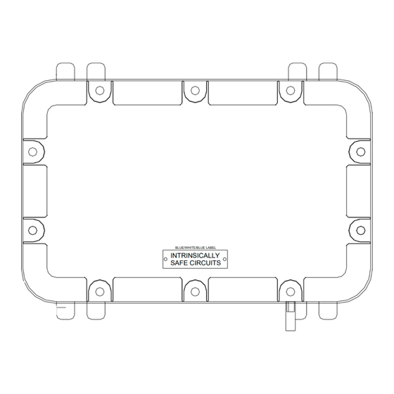
Page 4: General Wiring Layout
Cables of intrinsically safe circuits must be protected from mechanical damage, identified light blue and enter the enclosure through light blue cable glands. Mains Supply and Motor Supply cables must be sized to suit the Motor being connected. Reversing Starter EExd IIB T5... -
Page 5: Intrinsically Safe Circuits
0.6 – 1.0A Overload Relay – LRD05 1.0 – 1.6A Overload Relay – LRD06 1.6 – 2.5A Overload Relay – LRD07 2.5 – 4.0A Overload Relay – LRD08 Adjust the overload to suit the motor current rating. Reversing Starter EExd IIB T5... -
Page 6: Starter Schematic Drawings
Starter Schematic Drawings SWITCH AMPLIFIER 1 IMI-22EX-R SWITCH AMPLIFIER 2 IMI-22EX-R SWITCH AMPLIFIER 3 IMI-22EX-R Reversing Starter EExd IIB T5... -
Page 7: Mains Supply And Motor Connection
Connection Drawings Mains Supply and Motor Connection CONTROL PANEL EARTH POINT All cables must enter the enclosures through the pre-drilled and tapped holes using correctly fitted EExd rated cable glands. Reversing Starter EExd IIB T5... -
Page 8: Motor Limit Switch Connections
NOTE: REFER TO P18 ON GA25.15HXDT4 INSTRUCTION MANUAL FOR FULL LIMIT SWITCH DIAGRAM ADDITIONAL LIMIT LIMITS CONTACTS (16-21) (61-64) L2 L3 X1 X2 L2 L3 X1 X2 LINK TERMINALS 6 TO 8 AND 8 TO 10 Reversing Starter EExd IIB T5... -
Page 9: Push Button Connections
Connection Drawings Push Button Connections Reversing Starter EExd IIB T5... -
Page 10: Shoot Bolt Isolator Switches
Connection Drawings Shoot Bolt Isolator Switches L2 L3 X1 X2 L2 L3 X1 X2 Reversing Starter EExd IIB T5... - Page 11 Blank Supplied by: GfA ELEKTROMATEN UK Ltd Agincourt Road, Warwick, CV34 6XZ, United Kingdom Telephone: 01926 452452 Fax: 01926 336417 E-mail: sales@ gfa-elektromaten.co.uk Web Site: www.gfa-elektromaten.co.uk...
Need help?
Do you have a question about the EExd IIB T5 and is the answer not in the manual?
Questions and answers