
Related Manuals for GFA LB 700


Summary of Contents for GFA LB 700
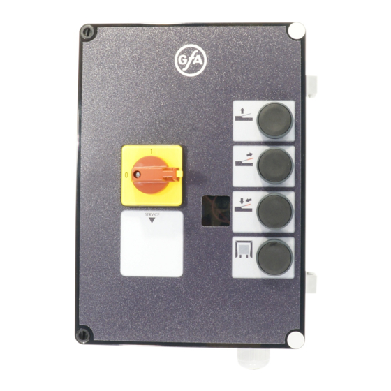
- Page 1 Installation instructions LB 700 Model: 20070000 -en- Status: 51171468 _h_08.2018 0 0 0 0 0 0 0 0 0 0 0 5 1 1 7 1 4 6 8 XXXXX...
- Page 2 GfA ELEKTROMATEN GmbH & Co. KG Wiesenstraße 81 • 40549 Düsseldorf www.gfa-elektromaten.de info@gfa-elektromaten.de...
-
Page 3: Table Of Contents
Contents General safety instructions .................... 4 Specifications ....................... 5 Recommended installation .................... 6 Installing the housing ....................6 Check the power supply connection ................7 Wiring the dock leveller to the control ................8 ... -
Page 4: General Safety Instructions
1 General safety instructions Intended use The controller is intended for the actuation of dock levellers with a hinged wedge lip or an extendible lip. Operating safety is ensured only when the controller is used as intended. No liability is accepted for any use other than that described in these instructions. -
Page 5: Specifications
1 Specifications LB 700 Supply voltage 3~400V,N,PE Fusing onsite available A tr. Max hydraulic unit power Number of valves Valve voltage V DC Max valve current Max controller power input Internal fusing A tr. External lighting fusing A tr. Traffic lights maximum power... -
Page 6: Recommended Installation
2 Recommended installation Your dock leveller can be put into operation quickly and safely when you follow the recommended procedure below: • Install the housing • Check the power supply connection • Wire the dock leveller to the controller • Rapid adjustment The dock leveller can now be operated. -
Page 7: Check The Power Supply Connection
4 Check the power supply connection Warning - Danger to life from electric current! Switch the mains OFF and check that the cables are de-energised Observe the applicable regulations and standards Make a proper electrical connection Use suitable tools Important note –... -
Page 8: Wiring The Dock Leveller To The Control
5 Wiring the dock leveller to the control Once installed, the dock leveller controller must be wired to the electrical componentry of your dock leveller system. Connecting the hydraulic motor W PE Hydraulic motor Dock leveller controller terminal block Dock leveller system terminal for hinged lip Dock leveller controller terminal block Platform / hinged lip valve Dock leveller system terminal for extendible... -
Page 9: Rapid Adjustment
6 Rapid adjustment After switching ON the controller, you can select the function for the dock leveller. 1. Switch ON 2. Select menu Press and turn the selector 3. Select hinged lip extendible lip 4. Save program item Press the selector and select next program function by repeating the procedure from 2 Continue for all further settings. - Page 10 Parameters for hinged lip mode 2. Select the program function 3. Time selection Min lip advance time 3,0 Seconds Max lip advance time 20,0 Seconds Max platform raising time 20,0 Seconds Autoreturn raising time 20,0 Seconds Autoreturn lowering time 20,0 Seconds Parameters for extendible lip mode 2.
-
Page 11: Pcb Overview
7 PCB overview Ser.Nr. : xxxxxxxx Artikel Nr. 20-30004984 HW x.x SW x.x 1,6A tr. F2= 1,6A tr. 10.1 10.3 10.5 + - + - + - 10.2 10.4 Power supply terminal Traffic light indicators / lighting Hydraulic motor terminal Vehicle shelter Valve terminal Display... -
Page 12: Terminal Diagram
1 Terminal diagram X1 Supply X2 Hydraulic motor X3 Dock leveller valves W PE N PE ⓑ ① ② ⓐ ⓒ 3~ 400V, N, PE : Motor Hinged lip Extendible lip Extendible lip X5 Wheel chock sensor X6 Vehicle detector ⓐ... -
Page 13: Control Programming
2 Control programming 1. Switch ON programming Press the selector for three seconds until 00 appears on the display 2. Adjustment Turn the selector until the program function you want appears, and confirm 3. Select function Turn the selector and select the function you want 4. -
Page 14: Programmingtable
3 Programmingtable Operating modes 2. Menu selection and 3 Setting 4 Storing confirmation Operating mode Dock leveller with hinged lip Press setting button Dock leveller with telescopic lip (2 valves) Energy-saving mode Press setting button Positions Minimum extension 1.0 - 3.0 Seconds Press setting duration, lip button... - Page 15 Safety functions 2. Menu selection and 3 Setting 4 Storing confirmation Wheel-block sensor Without sensor Press setting button With sensor Vehicle detector Without detector Press setting button With detector Position sensor for Without sensor Press setting dock leveller button Sensor with permanent contact Sensor with pulse contact Signals Red/green traffic lights,...
- Page 16 Functions 2. Menu selection and 3 Setting 4 Storing confirmation Release / Locking of Press setting dock leveller / door button Release via door contact Release via door contact and vehicle detector Release via door contact and door release via vehicle detector Vehicle shelter None...
- Page 17 Sensor 2. Menu selection and 3 Setting 4 Storing confirmation Hinged wedge sensor 00 = Telescopic lip Press setting 01 = sensitive button 20 = insensitive Maintenance Maintenance cycle 01-99 corresponds to 1,000- Press setting counter pre-selection 99,000 cycles to be counted button down Response of...
- Page 18 Info 2. Menu Display selection and confirmation Cycle counter info, Press setting 7-digit display button Coefficients of powers of ten from one million down to one are displayed successively 1,000,000 HT = 100,000 ZT = 10,000 1,000 Info on last two faults Press setting The two most recent faults detected are button...
-
Page 19: Description Of Dock-Leveller Functions
4 Description of dock-leveller functions The rapid adjustment procedure must have been completed and the dock leveller has to be at its home position Dock leveller with hinged lip Pressing the “Open” button The platform is raised. The hinged lip automatically folds out to the top limit position. -
Page 20: Dock Leveller With Telescopic Lip (2 Valves)
Dock leveller with telescopic lip (2 valves) Pressing the “Open” button ① The platform is raised. Releasing the “Open” button Platform stops rising and is lowered after 2 seconds, provided that no further command is issued. Pressing the “Telescopic lip” button ② The telescopic lip extends. - Page 21 Pressing the “Auto return” button The dock leveller is automatically raised and then lowered again until its home position is reached...
-
Page 22: Description Of Functions Of Additional Components
5 Description of functions of additional components Wheel-block sensor (X5) If the wheel block is placed against a tyre of the vehicle, the dock leveller can be operated. The external traffic lights change from green to red. Activation with menu 3.1 Vehicle detector, external (X6) If the vehicle is detected by the detector, the external traffic lights change from green to red. -
Page 23: Vehicle Shelter (X10)
Only when the wheel-block sensor is not engaged, will there be a changeover to a steady green signal at the traffic lights. Activation with menu 4.1 Internal red/green traffic lights The green lamp indicates that movement across the dock leveller is possible. For all other statuses, the red lamp will be lit. -
Page 24: Control-Device Connection Diagram For T801 (Optional)
6 Control-device connection diagram for T801 (optional) 1 2 3 4 5 6 ws br gn ge gr rs T 801 “Open” control button Connection cable “Stop” control button Terminal strip “Close” control button Plug-in connector T801 Control unit... -
Page 25: Control-Unit Status Display
7 Control-unit status display The dock-leveller control unit can display up to three different statuses, one after the other. The displayed status code consists of a letter and a number. Here a distinction is made between a fault display (letter F) and an operation display (letter P). - Page 26 Display Fault description Measures for fault correction Processor fault Reset by switching off and on via the mains switch. Replace the control unit if necessary. ROM error Reset fault status by switching off and on via mains switch. Replace the control unit if necessary. Register error RAM error Hydraulic motor fault...
-
Page 27: Declaration Of Incorporation / Declaration Of Conformity
EMC Directive 2014/30/EU within the meaning of RoHS Directive 2011/65/EU The following requirements from Appendix I of GfA ELEKTROMATEN GmbH & Co. KG the Machinery Directive 2006/42/EC are met: declare under our sole responsibility that the 1.1.2, 1.1.3, 1.1.5, 1.2.1, 1.2.2, 1.2.3, 1.2.4.2,...
Need help?
Do you have a question about the LB 700 and is the answer not in the manual?
Questions and answers