
Related Manuals for Sierra TM100


Summary of Contents for Sierra TM100
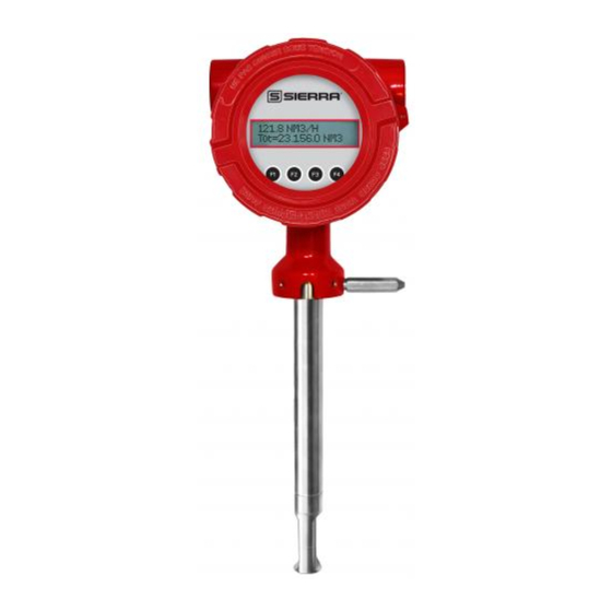
- Page 1 TM100 Thermal Mass Flow Meter Instruction Manual Document: S-IM-TM100 | Rev B_PN 110068 www.sierrainstruments.com...
- Page 3 TRADEMARKS TM100™, TM-Cal™, Gas-Mix™, FlowTrak™, TM100-View™, and DigiSense™ are trademarks of Sierra Instruments, Inc. Other product and company names listed in this manual are trademarks or trade names of their respective manufacturers.
- Page 4 TM100 Disclaimer Warnings and Cautions General Safety Information We use caution and warning statements throughout this book to draw your attention to important information. Symbol Key Symbol Symbol Meaning Description This statement appears with information that is important to protect people and equipment from Warning damage.
- Page 5 TM100 Disclaimer CAUTION • Caution! Before making adjustments to the TM100, verify the flow meter is not actively monitoring or reporting to any master control system. Adjustments to the electronics will cause direct changes to flow control settings. • Caution! All flow meter connections, isolation valves and fittings for hot tapping must have the same or higher pressure rating as the main pipeline.
- Page 6 Sierra Instruments by e-mail (see inside front cover). For urgent phone support you may call (831) 373-0200 between 8:00 a.m. and 5:00 p.m. PST. In Europe, contact Sierra Instruments Europe at +31 72 5071400. In the Asia-Pacific region, contact Sierra Instruments Asia at +8621 5879 8521.
-
Page 7: Table Of Contents
TM100 Introduction Table of Contents 1. Introduction Pages 9-21 a. Quick Start Guide ............... . . p. 9 b. - Page 8 TM100 Table of Contents 6. Maintenance Pages 85-93 a. Safe Meter Removal from Retractor ............p. 85 b.
-
Page 9: Quick Start Guide
Initializing... Check the remaining flow meter settings by accessing the meter settings either through the front panel of the display or by using the TM100-View Software. Record the settings in the spaces given for items A - F on the following page. - Page 10 20mA = Confirm the correct gas is selected for your application in the Gas-Mix menu Your Notes: If you are experiencing any problems after completing this procedure, please call the Sierra Instruments Tech Department at 831-373-0200 to review this information.
-
Page 11: Menu Trees
TM100 Introduction Menu Trees Fig. 1.1: TM100 Menu Tree - Main Menu Enter menu by scrolling to display 4 and entering the password MAIN MENU I/O FLO DSP EXIT Display Menu, p. 15 Flow Menu 1, p. 13 If RS485 hardware detected... - Page 12 TM100 Introduction Fig. 1.2: TM100 Menu Tree - Digital Outputs MAIN MENU I/O FLO DSP EXIT Set I/O PUL 420 EXIT Not used OUT= Pulse Pulse NXT OK HiFloAlm LoFloAlm HiTempAlm LoTempAlm Pulse Alarm output SystemAlm Select 1 of 3 methods to scale the pulse output High Flow Alarm Pulse Output OUT= HiFloAlm P/U U/P FEQ EXIT NXT OK HiFloAlm=500 SCFM PLS/UNT=2 UNT/PLS=0.5 MaxFreq=100Hz CHG OK CHG OK CHG OK CHG OK Low Flow Alarm...
- Page 13 TM100 Introduction Fig. 1.3: TM100 Menu Tree - Flow Menu 1 MAIN MENU I/O FLO DSP EXIT FLOW MENU 1 DGN UNT FM2 EXIT Flow Menu 2 Menu, p. 14 DIAGNOSTIC FLO UNT=SCFM SCFM SCFH SIM TM-Cal EXIT NM3/H NM3/M KG/H...
- Page 14 TM100 Introduction Fig. 1.4: TM100 Menu Tree - Flow Menu 2 MAIN MENU I/O FLO DSP EXIT FLOW MENU 1 DGN UNT FM2 EXIT FLOW MENU 2 GAS SPC PRM EXIT Parameters Level 2 Flow cutoff in selected units K fact = 0% Cutoff=12.5 SCFM...
- Page 15 TM100 Introduction Fig. 1.5: TM100 Menu Tree - Display Menu MAIN MENU I/O FLO DSP EXIT DISPLAY/PASSWORD DSP PSW EXIT Display 1 Line 1 FLo rate DSP1L1=FLo rate PASSWD=1234 Total NXT OK CHG OK Elps Display 1 Temp Line 2 Alarm FLo rate DSP1L2=Total Total NXT OK Elps Display 2 Temp Line 1 Alarm FLo rate DSP2L1=temp Total NXT OK Elps Display 2 ...
- Page 16 TM100 Introduction Fig. 1.6: TM100 Menu Tree - TM-Cal™ Menu MAIN MENU I/O FLO DSP EXIT FLOW MENU 1 DGN UNT FM2 EXIT DIAGNOSTIC MENU SIM TM-Cal EXIT TM-Cal MENU EXIT VERIFY TM-Cal? Hold value Flo: Hold value Go to zero...
- Page 17 TM100 Introduction Fig. 1.7: TM100 Menu Tree - Gas-Mix Menu MAIN MENU I/O FLO DSP EXIT FLOW MENU 1 DGN UNT FM2 EXIT FLOW MENU 2 GAS SPC PRM EXIT Methane GAS=Methane GAS=%Mix Select up to five gases for Gas NXT OK NXT OK Mix. Be sure mixture equals 100%. Nitrogen Helium Nat.Gas(mix) Methane = 65 % Argon UP DN OK Hydrogen CO2 = 30 % Propane UP DN OK Butane Oxygen Nitrogen = 5 % Ethane UP DN OK %Mix Helium = 0 % UP DN OK Argon = 0 %...
- Page 18 Total number of power cycles Screen 18 CAL‐V= 0.1 CAL‐V measurement value Err_tot=0 Display 19 Number of errors in total flow measurement Pwr Off=48.0 Elapsed time of meter power off in hours TM-Cal = 0.1 TM-Cal™ measurement value Screen 19 Fig. 1.9: TM100 Menu Tree - Reset Flow Total F3 & F4 pressed at the same time will initiate a "Total" reset Reset Total? NO YES Resetting Total ...
- Page 19 Calibration Validation Validate the calibration of the TM100 in the field using the TM-Cal™ test. The goal of Calibration Validation is to provide operators with the ability to verify that the meter is capturing accurate data at scheduled recalibration times - or at any time - instead of sending the meter back to the factory for recalibration.
- Page 20 Introduction Flow Calibration Every TM100 flow meter is set to the customer's configuration at the factory using an App ID which is generated by the on-line configurator. The App ID specifies the gas type, flow range, serial communication and other settings in the meter. If these settings match the final customer application, the meter is ready to use.
- Page 21 Panel for field configuration of flow meter settings such as gas selection, 4-20mA scaling, pulse output scaling, pipe area, flow cutoff, flow filtering, display configurations, diagnostics, communication parameters, and alarm limits. Fig. 1.10: TM100 Function Diagram Standard I/O 12-24VDC Input...
-
Page 22: General
TM100 Installation Installation Scope This section describes how to install the Sierra Instruments TM100 Flow Meter and how to get started. Installation methods will vary according to the flow meter type (insertion or inline). For TM100 Insertion Types: Determine lateral position on the pipe. -
Page 23: Lateral Placement
Instructions for Flow Meter Lateral Placement Install the TM100 flow meter so that it is far enough away from bends in the pipe, obstructions, or changes in line sizes to ensure a consistent flow profile. See Fig. 2.1 below for your meter type. - Page 24 Fig. 2.2: Installation at 180° Alternate Installations - Vertical Pipes or Restricted Installation Spaces When restricted physical installation space exists, the TM100 can also be installed at other angles. Please note that the display and the enclosure orientation can be rotated in 90° increments.
- Page 25 2. Assemble the compression fitting and branch fitting hand tight onto the probe of the TM100. 3. Insert the probe into the hole in the pipe and use the TM100 probe and compression fitting to align the branch fitting with the hole and the probe perpendicular to the pipe.
-
Page 26: Installation Depth
TM100 Installation Installation Depth The installation depth of the sensor in the pipe is dependent on the pipe size. To get the most accurate reading, proper placement of the sensor window within the pipe is necessary. As shown in Fig 2.5, the end of the sensor window should be 0.73" (18.5 mm) past the center line of the pipe. -
Page 27: Mounting Instructions
Installation Mounting Instructions - Compression Fittings (TM100 Only) The TM100 is mounted through a 0.781" hole and a female NPT branch outlet in the customer's pipe. Insertion style flow meters are not designed for use in pipes smaller than 1½". - Page 28 TM100 Installation Mounting Instructions - Compression Fittings (Inline and Insertion Meters Previously Installed) In cases where a compression fitting has already been swaged in an inline flow body or an insertion meter, use the following procedure. • Carefully insert the probe with swaged ferrules into the fitting until the front ferrule seats against the fitting (see Figure 2.7).
- Page 29 Installation Rotating the Enclosure The TM100 enclosure has been designed to allow the enclosure to rotate for optimal viewing of the display. To rotate the enclosure, first loosen the two set screws near the Flow Direction Indicator, then unscrew and remove the flow direction indicator. Rotate the enclosure into the desired position, reinstall the flow direction indicator, and tighten the set screws.
- Page 30 TM100 Installation Changing the Orientation of the TM100 Optional Display The optional display can be rotated in 90° increments for optimum viewing of the screen. First, open the enclosure by unscrewing the enclosure cap and loosen the two captive screws to open the display assembly.
- Page 31 TM100 Installation Installation of a New Retractor Assembly 1. Remove collar clamp from probe using a 3/16" Hex Key. 2. Remove meter probe from retractor assembly and leave the ball valve open. Keep the collar spacer on the probe so it is not misplaced.
- Page 32 TM100 Installation 4. Carefully slide the probe through the retractor assembly and through the hole to see if there is interference by touching the pipe wall with the end of the probe on the far side or until the probe cannot go deeper.
- Page 33 TM100 Installation 5. Using the equation (L + D/2 + 0.73") from Figure 2.12, calculate the insertion depth and mark on the probe while measuring from the end of the probe. 6. The Retractor Clearance table of Figure 2.21 lists the space required to remove the meter from the retractor.
- Page 34 TM100 Installation 7. Insert probe back into the retractor to the depth mark and hand-tighten the compression fitting. Make sure collar spacer is in place on the probe. 8. Verify that flow direction indicator is in line with pipe and in the direction of flow.
- Page 35 Connect the power and signal wires to the terminal blocks according to the label and instructions on the following pages. Cut all wires as short as allowable for a minimum service loop. Obtain the correct length for the TM100 wires using one of these methods: •...
- Page 36 • All plumbing and electrical installations of flow meters must be in compliance with local codes, the end user’s best engineering practices, and manufacturer’s recommendations. • Do not install the TM100 enclosure near an igniter, igniter-controller or switching equipment to eliminate the possibility of noise interference.
- Page 37 External DC power supply must provide 12 to 24VDC (10 to 30VDC full input power range) at 6 Watts minimum. With 12VDC power, the TM100 can use up to 500mA. With 24VDC power, the TM100 can use up to 250mA.
- Page 38 TM100 Wiring 4-20mA Output Wiring: Customer-Supplied Power Source (Recommended) Bring the wiring in through either conduit hub. Connect the 4-20mA flow rate, 4-20mA temperature, and HART communication option wiring as shown in the diagram below. Fig. 3.3: 4-20mA Output Wiring for Isolated Customer-Supplied Power Source...
- Page 39 Bring the wiring in through either conduit hub. Connect the 4-20mA flow rate, 4-20mA temperature, and HART communication option wiring as shown in the diagram below. Fig. 3.4: 4-20mA Output Wiring for Loop Power Provided by TM100 Customer PLC or DCS...
- Page 40 The Pulse/Alarm output is an open collector circuit capable of sinking a maximum of 20mA of current. Pulse or alarm selection is programmed using the display or TM100-View Only one option, pulse or alarm, can be active at a time.
- Page 41 The pulse/alarm output is an open collector circuit capable of sinking a maximum of 20mA of current. Pulse or alarm selection is programmed using the display or TM100-View™. Only one option, pulse or alarm, can be active at a time.
- Page 42 No Termination (Open) NOTE! • In order to use the RS485 feature on the TM100, this feature must be chosen when the meter is ordered from the factory. Modbus RTU and BACnet MS/TP is not available with meters ordered with the Pulse/Alarm option.
- Page 43 TM100 Wiring HART Wiring The HART connections are made as shown in the diagram below. NOTE! Meters ordered with HART will be configured for flow as default. If the customer changes the 4-20mA output to temperature, HART should report temperature.
- Page 44 TM100 Wiring HART 4-20mA Output Wiring: Handheld Communicator The 4-20mA current loop connections are made as shown in the diagram below. A hand-held HART communicator can be connected to test points TP12 (+) and TP13 (-) with clip leads or to the 4-20mA terminal block.
- Page 45 HART 4-20mA Output Wiring: Loop Power Provided by TM100 The 4-20mA current loop and HART modem connections are made as shown in the diagram below. Fig. 3.10: HART 4-20mA Output Wiring, Loop Power Provided by TM100 Customer PLC or DCS...
- Page 46 The TM100 has an optional 2 line x 16 character display with four mechanical buttons. The meter can be programmed by using the display and configuration panel. The configuration panel can be accessed by removing the TM100 cap. Be sure to replace the cap after you are done configuring the TM100.
- Page 47 TM100 Operation Measurement Mode Display Screens In the measurement mode, there are four different display screens (Display 1, 2, 3 and a prompt screen to enter the programming mode). Two display screens are user programmable (refer to Display Setup p. 54). Scrolling through the display is accomplished by pressing the F1 or F2 key to view the next or previous screen.
- Page 48 TM100 Operation Programming Data Entry using the Display and Configuration Panel There are two basic types of menu entries: one for changing value or string and one for selecting from a selection list. To Change a Value or String : VALUE = 0.91234...
- Page 49 TM100 Operation Enter the correct password, then follow the instructions for changing a value as specified above. The default Level 1 password is “1234”. If the wrong password is entered, the message “Wrong Password” will display and then return to the programming entry screen.
- Page 50 TM100 Operation 4 mA = 0 SCFM Enter the value for the 4mA and press OK (F4). NOTE! When the flow rate exceeds the programmed value for the 20mA set point, the analog output will stay at 20mA and an alarm code will be generated.
- Page 51 TM100 Operation Pulse/alarm Output The Pulse/Alarm feature can be accessed from the Main Menu, press I/O (F1). EXIT Press OUT (F1) to select the pulse output. The following screen will show: OUT = Pulse Press NEXT (F1) to cycle through output options until you have the selection for "OUT=Pulse" and press OK (F4).
- Page 52 MaxFlo=5000 SCFM NOTE! If the flow rate exceeds the maximum pulse rate (frequency), the output will stay at 100 Hz and the TM100 will issue an alarm code. Alarm Output To access the Pulse/Alarm feature, press I/O (F1) key from the Main Menu screen.
- Page 53 TM100 Operation OUT = HiFloAlm Then press NXT (F1) to select the correct alarm and press OK (F4). Selections are: Not used Pulse HiFloAlm = High Flow Alarm LoFloAlm = Low Flow Alarm HiTempAlm = High Temperature Alarm LoTempAlm = Low Temperature Alarm System Alarm When the output is set to Alarm and there is no alarm condition, the output will be on (0 volts).
-
Page 54: Hart
TM100 Operation Options for serial communication are: None Modbus BACnet HART NOTE! Any selection other than “None” requires the communication option for the selected communication type. If enabling a communication option, see the Communications Protocols section of this manual. Display Setup There are four display screens that you can cycle through in normal operating mode (see Figure 4.2... - Page 55 TM100 Operation When the selection is correct, press OK (F4) to accept. The display will then go through the same process for all four lines of the two programmable displays (DSP1L1, DSP1L2, DSP2L1 and DSP2L2). After the last line of Display 2 is accepted, the display will show the following menu: ALTERNATE = Off This menu allows you to alternate between menu display 1 and 2 every few seconds.
- Page 56 MMSCFD (MMCFD) NM3/H LBS/H NLPM NM3/D MCFD (MSCFD) NM3/M LBS/M NLPS SLPM MMSCFM (MMCFM) KG/H LBS/S SM3/M SCFD MT/H WARNING! The TM100 re-calculates area, 4 and 20mA values, maximum flow for the pulse output and flow cutoff when changing flow units.
- Page 57 TM100 Operation Temperature Units After pressing OK (F4) to accept the Flow unit the display will prompt for the temperature unit setting: TMP UNT= ° F Press NXT (F1) to change selection and OK (F4) to accept. Selections for Temperature units are: °C or °F.
- Page 58 TM100 Operation Accessing Flow Parameters and Alarm Settings This is the menu used to set various flow parameter values. They are: flow cutoff, pipe diameter, filter, high and low alarm for flow and temperature. NOTE! The parameters in this menu are set to the customer specifications at the factory. They should only be changed when changing the application of the flow meter.
- Page 59 Settings for the alarms directly follow the flow parameters for flow cutoff, pipe diameter, and filter value. These alarms can be used without the digital output assigned to the alarm. If that is the case, the alarm status will only be shown on the display, through serial communication, or TM100-View . If the digital output is assigned to an alarm, changing the value here will change that setting.
- Page 60 TM100 Operation Low Flow Rate Alarm This is the lower flow limit alarm value that can be associated with the alarm output. An alarm code is generated when the flow value is below this limit. If no alarm is needed, set this value to zero.
- Page 61 TM100 Operation CAUTION! If the 4-20mA and/or the Pulse/Alarm outputs are connected to controllers, set the controllers to “manual” to ensure that the simulated signals do not cause false controller action. The menu is accessible from the "Main Menu" by pressing FLO:...
- Page 62 NOTE! Simulation Mode will be cleared if the power is cycled. K Factor The K Factor allows the user to adjust the meter’s calibration. The Sierra Instruments flow meter increases the calculated flow rate by the K Factor. This results in a direct scaling of the meter’s output across the entire full range.
- Page 63 Press YES (F4) and enter password to reset total and elapsed time. Press NO (F1) to cancel. NOTE! This feature is not available on non-resettable units. Totalizer Rollover: The TM100 has an automatic roll-over function. The total flow count of the TM100 will roll over after 99,999,999,999. Except for:...
- Page 64 If the TM-Cal™ test does not produce a "PASS" result, refer to "TM-Cal™ Test Results" on page 66. NOTE! If the TM-Cal™ test is performed using the Sierra Instruments TM100-View™ software, at the completion of the test, a TM-Cal™ Certificate may be printed for a record of the test. This certificate will display a pass/fail result.
- Page 65 TM100 Operation Press TM-Cal (F2). The display will show: MENU TM-Cal EXIT Press VER (F1) to perform the TM-Cal™ verification test. VERIFY TM-Cal? Press OK (F4) to continue. Flo: Hold value EXIT Press NXT (F1) to toggle between "Hold value" and "Go to zero." During the TM-Cal test, "Hold value"...
- Page 66 • Remove the probe from the pipe, clean the sensor, and perform the test again under a normal or high flow rate. If a "Warning or "Fail" result is displayed after repeating the test, please call Sierra Customer Service at (831) 373-0200 for assistance.
- Page 67 TM100 Operation After installing your TM100 flow meter, power up the device. When the meter finishes initializing, it will begin to monitor flow in the assigned gas and flow units. Accessing the Gas-Mix Gas Selection Menu Feature Enter the programming mode on the meter (refer to p. 48) and then follow these instructions to...
- Page 68 TM100 Operation To create a "Gas Mix," choose %Mix from the list and press OK (F4). Gas=%Mix NOTE! • Gas mix total (sum of percentages) must equal 100%. • Any gases not included in the gas mix should have percentages set to 0%.
- Page 69 Press OK (F4) to set the mixture. in Gas-Mix The TM100 will begin to monitor flow based on the algorithm for the gas selected in the Gas-Mix feature. The screen will show the flow in units and the total flow similar to the example below: 1162.52 SCFM...
- Page 70 NOTE! The data shown in brackets < > represents one byte of data. Modbus Indicators Green LED indicator LP3 cycles on and off to indicate that the TM100 is operating. Orange LED indicator LP2 blinks when Modbus signals are received and Yellow LED P1 blinks when Modbus signals are transmitted.
- Page 71 TM100 Communication Communication Protocol and Parameters To program the communication parameters, start at the Main Menu: MAIN MENU EXIT Then press I/O (F1) to set Inputs/Outputs: SET I/O EXIT Then press COM (F1) to select communication parameters. Set Bus protocol for Modbus: Comm=Modbus Press NXT (F1) repeatedly until "Modbus"...
- Page 72 Status 2 40018 Control Register (Write Only), Reset Total = 2, Perform TM-Cal = 173, Abort TM-Cal = 174 40019 16-bit int Model Status (Read only) TM100 = 0x800 40020 32-bit float LSW Flow User selected 40021 32-bit float MSW...
- Page 73 Last TM-Cal Value 40211 32-bit float MSW Last TM-Cal Value **Last TM-Cal Data and Time is only valid when using TM100 View Software. NOTES! • In the table, LSW means Least Significant Word, and MSW means Most Significant Word. In this case a “word”...
- Page 74 TM100 Communication Read Multiple Registers (command 03) This command reads one or more 16 bit registers from the TM100 and has the following format: Request: <Meter Address> <Command code=03> <Register start address high> <Register start address low> <Register count high> <Register count low> <CRC high> <CRC low>...
- Page 75 TM100 Communication Table 5.2: Status Bits Definitions for Command 04, Modbus Address 40016 Definition Comment Power up indication Cleared when out of the power up sequence Flow rate reached high limit threshold Set limit to zero to disable Flow rate reached low limit threshold...
- Page 76 TM100 Communication Write Multiple Registers (Command 16) This command is restricted to writing to the gas mix percentage settings in registers 40058 - 40061. Reference Table 5.5, pg 79. The preset single register command is not allowed to write to these registers.
- Page 77 TM100 Communication First byte (MSB of lower register) Data bit Value bit S15 Second byte (LSB of lower register) Data bit Value bit S7 Third byte (MSB of higher register) Data bit Value bit Sign Fourth byte (LSB of higher register)
- Page 78 TM100. Selecting TM100 Gases and Gas Mixes Modbus register 40056 selects the gas type, which may be a pure gas (plus NAESEB natural gas composition) or custom gas mix. Register 40057 will read zero, and register 40056 will read the gas sellection tha was chosen.
- Page 79 TM100 Communication Table 5.5: TM100 Modbus Holding Registers for Gas-Mix 40056 16-bit int Gas type selection See table of gas selection codes for Modbus 40057 16-bit int Gas type selection 40058 32-bit float LSW Methane (C1) percentage Percent (31.4 = 31.4%)
- Page 80 Analog Input 4 = Elapsed Time since reset BACnet Indicators LED indicator LP3 cycles on and off to indicate that the TM100 is operating. LED indicator LP2 blinks when BACnet signals are received and LP1 blinks when BACnet signals are transmitted.
- Page 81 9600, 19200, 38400, 57600, 76800, 115200 TM100 Character sets supported: ANSI X3.4, UTF-8 Sierra Instruments BACnet vendor ID: 650 For more information about BACnet visit http://www.bacnet.org/. Communication Protocol and Parameters To program the communication parameters, press I/O (F1) key from the Main Menu.
- Page 82 TM100 Communication Next select the MS/TP Mac address. The selection is from 0-127. Please note that only one device can be on a MS/TP Mac address. MAC_ADD=23 Next select the MS/TP Max Master using CHG (F1). The selection is from 0-127. Press OK (F4) to accept the setting.
- Page 83 Communication Scope - HART Communications The Sierra Instruments TM100 transmitter complies with HART Protocol Revision 7.1. This section of the manual specifies all the device-specific features and documents HART Protocol implementation details (e.g., the Engineering Unit Codes supported). The functionality of this Field Device is described sufficiently to allow its proper application in a process and its complete support in HART-capable Host Applications.
- Page 84 Variable. HART Communication is supported on this loop. The 4-20mA output of the TM100 should be configured for flow rate when using HART. If the 4-20mA output is set to report temperature, HART communication will report the 4-20mA value for temperature rather than flow.
- Page 85 TM100 Communication Set Bus protocol for HART: Comm=HART Press NXT (F1) until HART is selected as shown and then press OK (F4) to accept the setting. NOTE! Power cycle is required for the new settings to take effect. Dynamic Variables Four Dynamic Variables are implemented.
- Page 86 TM100 Communication Additional Device Status (Command 48) Command #48 returns 2 Device-Specific Status bytes of data, with the following status information: These bits are set when an alarm or error condition is present. The bit automatically clears when the condition returns to its normal state.
- Page 87 Fixed current mode is implemented, using Command 40. This mode is cleared by power loss or reset. Damping Damping is standard, affecting only the PV and the loop current signal. Capability Checklist Manufacturer, model Sierra Instruments, TM100 Device Type Transmitter HART revision Device Description available Number and type of sensors...
- Page 88 CAUTION! BE SURE POWER TO METER IS SWITCHED OFF BEFORE ATTEMPTING TO ACCESS ELECTRONICS. If there is a problem and a loose connection is not found, please contact Sierra Instruments Customer Service for technical assistance at (831) 373-0200.
- Page 89 TM100 Maintenance FUSE REPLACEMENT WARNING! TURN INPUT POWER OFF BEFORE REMOVING OR INSTALLING A FUSE. USE ONLY RECOMMENDED FUSE REPLACEMENTS. Verify the fuse is defective by measuring it with an Ohm Meter (Two replacement fuses are provided with each unit). Replacement fuse is Littelfuse part number 0454.750MR...
- Page 90 TM100 Maintenance Instructions for Removing and Inserting the Meter from a Pressurized Pipe using the Retractor WARNING! Possible injury or damage to equipment may occur if the retractor is not used correctly. Please read the following instructions carefully prior to using the retractor.
- Page 91 TM100 Maintenance Step 2 - Remove the Probe from the Retractor Body After removing the probe from the flow stream (#1-4 on previous page), slowly loosen the compression fitting (see figure 6.1), until the pressure in the retractor is relieved.
- Page 92 TM100 Maintenance How to Insert the Probe into the Flow Stream (Valve closed, System Pressurized) Carefully, slide the probe into the retractor. Install the collar clamp just below the collar spacer, and tighten it in place on the probe. Slide the probe back out of the retractor until the cable is straight and taut.
- Page 93 TM100 Maintenance 3. Slowly open the ball valve to the full open position. Push the meter and probe into the pipe, then hand tighten the compression nut onto the compression fitting. NOTE! At a maximum system pressure of 150 psig, the force required to push the probe in place to tighten the compression nut will be approximately 66 lbs.
- Page 94 Troubleshooting Troubleshooting CAUTION! The electronics and sensor supplied by Sierra Instruments are calibrated as a single precision mass flow meter. Interchanging sensors will decrease the accuracy of the flow meter. If you experience any problem with your TM100, call Sierra Instruments Customer Service Department, Technical Assistance at (831) 373-0200.
- Page 95 If fuse is OK and unit still won’t power up, call Sierra Instruments for additional assistance Troubleshooting TM-Cal™ If the TM100 Meter fails a TM-Cal™ Calibration Validation test, there are a few reasons that could be the cause: 1. Flow rate in the pipe: •...
- Page 96 Inadequate power source. The TM100 requires 12 to 24VDC at to 6 Watts to operate. A 20 Watt power supply is recommended for powering the TM100 to ensure it operates properly under all temperature ventilation, and power on conditions. If the voltage supplied at the input terminals of the TM100 is not within the range of 10VDC to 30VDC, a variety of problems can occur including a dim display, inaccurate flow readings or faulty 4-20mA, pulse and communication interface.
- Page 97 PRM menu of FLOW MENU 2, refer to pages 10-11. Gas mix error Gas mix must equal 100%. One or more internal settings are corrupted or out of spec. Contact Sierra Instruments Check settings Service for instructions to verify settings.
- Page 98 TM100 Troubleshooting Alarm Codes continued The VTEMP Voltage is out of the acceptable range. This may be a result of failed electronics, VTEMP Volt Error parameters, or sensor connections. Refer to action of Alarm Code 22. The Delta T error between the sensor elements is too large. This may be a result of failed Delta T Error electronics, parameters, or sensor connections.
- Page 99 TM100 Appendix Specifications Performance Specs Flow Accuracy: Air and Nitrogen (N2): ±1.0% of reading plus ±0.2% of full scale Other Gases: ±1.5% of reading plus ±0.5% of full scale Accuracy specification applies to customer's selected flow range Maximum range: 15 to 25,000 SFPM (0.07 to 118 NMPS) Minimum range: 15 to 500 SFPM (0.07 to 2.4 NMPS)
- Page 100 0-27,900 0-30,600 NOTE! To determine if the TM100 will operate accurately in other pipe sizes, divide the maximum flow rate by the pipe area. The application is acceptable if the resulting velocity is within the velocity range above. Maximum Flow Ranges for TM100 Inline Flow Meters...
- Page 101 NEMA 4X (IP67), aluminum, dual ¾” FNPT conduit entries. Flow Meter Installation: A 3/4" MNPT compression fitting is provided with the TM100 to connect with a customer supplied 3/4" female branch outlet welded to the pipe. Extra 3/4" and 1" MNPT compression fittings are an...
- Page 102 TM100 Appendix Agency Approvals CE: Approved EMC Directive; 2014/30/EU Electrical Equipment for Measurement, Control and Lab Use: EN61326-1:2013 Pressure Equipment Directive: 2014/68/EU Weld Testing: EN ISO 15614-1 and EN ISO 9606-1, ASME B31.3 FM (FM21US0123X) and FMc (FM21CA0089X): Approved Class I, Division 1, Groups B,C,D;...
- Page 103 FULL PORT BALL VALVE 9.0±.3 "LL" (231.0±7.5) PROBE C L SENSING AREA Ø.75 (Ø19.0) (18.5) Table 7.1: TM100 Insertion Meter with 316 stainless steel probe Probe Size Probe Size Dimension “LL” ± .10 [model code] [inches] [inches / millimeters] 15"...
- Page 104 FLOW DIRECTION INDICATOR ˝LL˝ PROBE NOMINAL LENGTH C L SENSING AREA .73 [18.5] ø.75 [19.1] Table 7.2: TM100 Insertion Meter with 316 stainless steel probe Probe Size Probe Size Dimension “LL” ± .10 [model code] [inches] [inches / millimeters] 6"...
- Page 105 TM100 Appendix Fig. 7.3: TM100 Inline Meter with Flow Body NPT End Connections Dimensions Table 7.3: TM100 Inline Meter with Flow Body and NPT End Connections Body Size Body Size Dimension “L” +/- .10 Dimension “H” +/- .25 [model code]...
- Page 106 TM100 Appendix Fig. 7.4: TM100 Inline Meter with Body 150 lb RF Flange End Connections Dimensions Table 7.4: TM100 Inline Meter with Flow Body and 150 lb RF Flange End Connections Dimensions Body Size Body Size Dimension “L” +/- .10 Dimension “H”...
- Page 107 Limited Warranty Policy- Register Online All Sierra products are warranted to be free from defects in material and workmanship and will be repaired or replaced at no charge to Buyer, provided return or rejection of product is made within a reasonable period but no longer than one (1) year for calibration and non-calibration defects, from date of delivery.
- Page 108 Appendix Pack your instrument carefully. Use the original packaging and foam or bubble wrap (packing peanuts NOT recommended) and include a copy of the RMA form (complete with Sierra supplied RMA number) with the unit(s). Ship the unit(s) to the following address: Sierra Instruments, Inc.
- Page 110 TM100 Appendix Glossary of Terms and Definitions American Wire Gauge NLPH Normal Liter per Hour Bara Bar absolute NLPM Normal Liter per Minute Contact Normal cubic Meter Calibration NM3/H Normal cubic Meter per Hour Change NM3/M Normal cubic Meter per Minute...
- Page 111 TM100 Appendix Index Access to Electronics, p. 35 Programming, p. 55 Alarm Codes, p. 97 Power Input Wiring, p. 37 Alarm wiring, p. 41 Preventative Maintenance, p. 89 Analog 4-20mA output, p. 49 Product Description, p. 19 Breakage or Damage of Probe, p. 88 Programming TM-Cal™, p.
- Page 112 Indicates compliance with the applicable European Union Directives for Safety and EMC (Electromagnetic Compatibility Directive 2014/30/EU). Enclosure Protection Classification per IEC 60529: Protected against the ingress of dust and Immersion. Sierra Instruments Inc. 5 Harris Court, Building L Monterey, CA 93940 North America: 1-831-373-0200 www.sierrainstruments.com...
Need help?
Do you have a question about the TM100 and is the answer not in the manual?
Questions and answers