Table of Contents
Advertisement
Quick Links
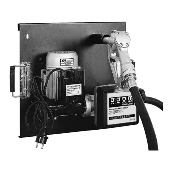
Wall Mounted Pump Kit
Instruction Manual
WARNING:
Read carefully and understand all INSTRUCTIONS before operating. Failure to follow the safety
rules and other basic safety precautions may result in serious personal injury.
Save these instructions in a safe place and on hand so that they can be read when required.
Keep these instructions to assist in future servicing.
REV 03/11/22
Advertisement
Table of Contents

Related Manuals for Macnaught FTWM120-001


Summary of Contents for Macnaught FTWM120-001
- Page 1 Wall Mounted Pump Kit Instruction Manual WARNING: Read carefully and understand all INSTRUCTIONS before operating. Failure to follow the safety rules and other basic safety precautions may result in serious personal injury. Save these instructions in a safe place and on hand so that they can be read when required. Keep these instructions to assist in future servicing.
-
Page 2: General Safety Regulations
GENERAL SAFETY REGULATIONS WARNING: The warnings, cautions, and instructions discussed in this instruction manual cannot cover all possible conditions or situations that could occur. It must be understood by the operator that common sense and caution are factors that cannot be built into this product, but must be supplied by the operator. -
Page 3: Declaration Of Conformity
DECLARATION OF CONFORMITY IN ACCORDANCE WITH THE DIRECTIVES 89/392/CEE - 91/368/CEE - 93/44/CEE – 89/336/CEE – 92/31/CEE THE MANUFACTURER: MACNAUGHT AMERICAS (813) 628-5506 | INFO@MACNAUGHTUSA.COM DECLARES THAT THE FOLLOWING PUMP MODELS: FTWM120-001 To which this declaration refers, conform to the following applicable regulations: EUROPEAN REGULATIONS: EN292-1-92 –... -
Page 4: Safety Devices
SAFETY DEVICES GENERAL SWITCH It is placed on the motor body and allows the operator to set it on standby in a very short time. Once the machine is stopped, the whole starting procedure can be repeated. HARMFUL FUNCTIONS The noise from the machine is below 70 dB (A). HARMFUL EMISSIONS Steam emission is so reduced to result irrelevant. -
Page 5: Technical Details
Electrical Power Item No. Model of Meter Flow Rate Current Voltage Power FTWM120-001 15111200 120LPM/32GPM 120V 1100W SAFETY PRECAUTIONS 1. During Diesel delivery always wear oil resistant and always wash hands with water and soap at the end. Always clean at once fuel stains to avoid slips and/or pollution. -
Page 6: Flow Meter
4. Check and tighten the screws which connect the pump and the board, pump and meter. For a better employment the unit should be placed as near as possible to level of liquid to be pumped. (Max. distance 2m). 5. Screw the delivery hose on the fitting of the flow meter and of the filling gun. 6. -
Page 7: Operational Problems
2. Macnaught’s liability is limited to replacement or repair of defective material within the warranty period, when returned freight prepaid to the distributor or their designated service depot. - Page 8 EXPLODED AND PARTS LIST Part No. Description Q’ty Part No. Description Q’ty Latex Washer Hose Connectors Pump Bolt M12 Inlet Gun base Outlet Board Nozzle Meter Bolt * Wearing parts.
-
Page 9: Operating Conditions
TECHNICAL DETAILS ELECTRICAL POWER POWER Connection Item No. Flow Rate Nominal (*) Inlet/outlet Current Voltage(V) Frequency 17310801 50/60Hz 80LPM 450W 1" 17311000 50/60Hz 100LPM 750W 1" 17311200 50/60Hz 120LPM 1100W 1" 17330900 60Hz 25GPM 450W 1" 17331200 60Hz 32GPM 1200W 1"... -
Page 10: Installation
MOVING AND TRANSPORT 1. Given the limited weight and size of the pumps (see overall dimensions), moving the pumps does not require the use of lifting devices. 2. The pumps were carefully packed before shipment. Check the packing material on delivery and store in the dry place. -
Page 11: Initial Start-Up
5. CONSIDERATIONS REGARDING DELIVERY AND SUCTION LINES DELIVERY 1. The choice of pump mode must be made keeping the characteristics of the system in mind. 2. The combination of the length of the tubing, the diameter of the tubing, the flow rate of the diesel fuel and the line accessories installed can create back pressure greater than the maximums anticipated such as to cause the (partial) opening of the pump by-pass with the consequent noticeable reduction of the flow rate supplied. -
Page 12: Daily Use
Extreme operating conditions can raise the motor temperature and, consequently, cause the thermal protection switch to stop it. Turn off the pump and wait for it to cool before resuming use. The thermal protection automatically turns off when the motor is sufficiently cool. In the priming phase the pump must blow the air initially present in the entire installation out of the delivery line. -
Page 13: Problems And Solutions
PROBLEMS AND SOLUTIONS ACCIDENTS CAUSES REMEDIES The Motor is not Lack of electric power Check the electrical connecting. turning. Rotor Jammed Check for possible damage or obstruction of the rotating components. Motor Problems Contact the Service Department Low voltage in the electric The motor turns slowly Bring the voltage back within the anticipated limits power line... - Page 14 DIAGRAM AND PARTS LIST Part No. Description Q’ty Part No. Description Q’ty BY PASS VALVE COVER SCREW M5 O-RING PIN 5 BY PASS SPRING PUMP COVER BY PASS VALVE SCREW M6 TERMINAL BOARD SCREW M6 DOUBLE-POLE SWITCH PUMP BODY TERMINAL BASE O-RING MOTOR ROTOR...
-
Page 15: Personal Safety
TECHNICAL DETAILS Item No. 15111200 Meter mechanism Nutating disk Flow rate range 20-120 LPM / 5-32GPM Operating pressure Max. 3.5 bar/50PSI Storage humidity Max. 95% Working temperature range -10 - 58°C Accuracy ±1% Inlet/Outlet connection 1" Weight 1.8 KGS * This Mechanical Fuel Meter can be used to measure the flow of kerosene, diesel oil, water or other fluids of low viscosity. -
Page 16: Calibration Procedure
As specific operating conditions (such as real flow rate, nature and temperature of the measured fluid) may affect the meter accuracy, a recalibration should be carried out after the installation has been completed. A new calibration is necessary each time the meter is disassembled for maintenance or when it is used to measure fluids other than kerosene. -
Page 17: Meter Unit
DISASSEMBLY/REASSEMBLY The meter can disassemble easily into its primary components without removing the body from the pipes. METER UNIT Disassemble the meter unit as follows: 1. Remove the reset knob by firmly pulling it straight out. 2. Loosen four retaining screws (#22). 3. - Page 18 EXPLODED AND PARTS LIST Part No. Description Q’ty Part No. Description Q’ty Name plate Meter body Reset knob O-ring 110.72x3.53 External cover O-ring 23.47x2.62 Meter Measuring chamber Screws 4x20 Measuring tray Body cover Measuring chamber Screw 5x16 Cylinder spring Bevel pinion Screws 4x20 O-ring 3.62x2.62 O-ring 4.47x1.78...
- Page 20 Macnaught Americas (813) 628-5506 | info@macnaughtusa.com * Read Manual Before Use! Size: 145x210mm 157克铜版纸 REV 03/11/22 2.09.05.30.1087...
Need help?
Do you have a question about the FTWM120-001 and is the answer not in the manual?
Questions and answers